
TEKTRONIX VX4240 VXIbus protocol waveform digitizer/analyzer module
Falling time (AF) measures the time it takes for a signal to drop from 90% steady state to 10% steady state, and returns the maximum/minimum/average values
Return the maximum/minimum/average value and corresponding address of the part where the overshoot (AO) signal exceeds 100% steady-state value
Return the maximum/minimum/average value and corresponding address for the part of the down rush (AU) signal below 0% steady-state value
Find the maximum/minimum voltage values and corresponding memory addresses within the specified sample range (AX/AM)
Pulse width (AW/AZ) measures the duration of pulse high/low levels, supports absolute zero or floating reference points, and returns maximum/minimum/average values
(2) Frequency domain analysis function
Function Name Description
FFT analysis (AC) fast Fourier transform, supports voltage (V) or power (dBm) units, can return maximum amplitude and frequency, harmonic parameters, etc
FFT+Hanning Window (AH) FFT with Hanning Window to reduce spectral leakage, suitable for non periodic signals
FFT+Blackman Harris Window (AQ) FFT with Blackman Harris Window, further suppressing spectral leakage and achieving higher resolution
Total Harmonic Distortion (THD) calculates the amplitude ratio of the fundamental wave to the first 5 harmonics, in dBc (relative to the carrier wave)
Signal to Noise Ratio (SNR) is the ratio of the fundamental amplitude to the amplitude of all non harmonic noise, measured in dBc
The difference between the fundamental amplitude and the maximum amplitude of the spurious signal (noise or harmonic) in the non spurious dynamic range (SFDR), measured in dBc
(3) Statistical and mathematical analysis functions
Function Name Description
Calculate the average voltage value within a specified sample range using the mean (AA)
The true RMS value (AT) calculates the true effective value of a signal (square root mean square), reflecting the actual power of the signal
The standard deviation (AS) reflects the degree of dispersion of sample data and can simultaneously return the proportion of data within the ± N σ range (N=1-9)
Integral (AI) calculation of the area under the signal curve (accumulated sample values multiplied by the sampling interval)
Differential (AD) calculates the difference between consecutive sample points, reflecting the rate of signal change
Cycle/Frequency/Duty Cycle (AY/AW/AZ) is based on zero crossing detection to calculate the signal cycle, frequency, and high-level duty cycle
(4) Recording and special analysis functions
Function Name Description
Record operation (AG) performs average, difference, and maximum/minimum value calculations on multiple records to generate new records
Single frequency DFT (AL) is a discrete Fourier transform for a specified frequency that returns amplitude (RMS) and phase (radians), supporting single/double precision
Zero crossing time (AZ) detects the zero crossing time of the signal, calculates parameters such as cycle and duty cycle, and the reference point is absolute zero
Installation and Operation Guide
1. Preparation and requirements before installation
(1) Tools and Environment
Essential tool: Phillips screwdriver.
Environmental requirements: The mainframe should provide sufficient heat dissipation (2.7 liters/second airflow, pressure drop of 0.19 mm H ₂ O, module temperature rise<10 ° C), operating temperature of 0 ° C~55 ° C, storage temperature of -40 ° C~85 ° C, relative humidity<75% (non condensing, 31 ° C~40 ° C).
(2) Switch settings (critical configuration, incorrect settings will cause module failure)
Description of switch name and position requirements
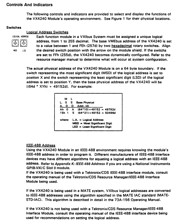
Logical address switch (S080) 1-255 (FFh is dynamically configured) base address calculation formula: [(64d × XYh)+49152d], it is recommended to match the slot number
The interrupt level switch (S081) 1-7 (0/8/9 disable interrupts) needs to match the interrupt handling level of the system controller
The Halt switch (S084) must be set to ON, otherwise the module cannot respond to VXIbus resource manager commands properly
The Bootstrap switch (S56) is set to OFF for factory testing purposes, and users do not need to adjust it
The memory size switch (S083) is preset by the factory and cannot be adjusted by oneself. It matches the hardware configuration of the memory
(3) Installation steps
Record the revised version of the module, serial number (top shield label), and switch settings, and fill in the installation checklist.
Confirm that the power supply of the host rack is turned off, and insert the module into any C/D size slot except for slot 0 (the D-size host rack should be adapted according to the host rack manual).
Tighten the module fixing screws to ensure that the front panel is grounded and avoid the risk of electric shock.
Connecting cables: The BNC interface uses RG58 coaxial cable to connect the device under test (UUT), while the DB25 interface can use CDS 73A-742P shielded connectors.
Check the overhead idle slot of the host: it needs to be covered with a blank panel to ensure heat dissipation; If there is a vacant slot on the left side of the module, the VME daisy chain jumper needs to be installed according to the host rack manual.
- OMRON
- ABB
- General Electric
- EMERSON
- Honeywell
- HIMA
- ALSTOM
- Rolls-Royce
- MOTOROLA
- Rockwell
- Siemens
- Woodward
- YOKOGAWA
- FOXBORO
- KOLLMORGEN
- MOOG
- KB
- YAMAHA
- BENDER
- TEKTRONIX
- Westinghouse
- AMAT
- AB
- XYCOM
- Yaskawa
- B&R
- Schneider
- KONGSBERG
- NI
- WATLOW
- ProSoft
- SEW
- ADVANCED
- Reliance
- TRICONEX
- METSO
- MAN
- Advantest
- STUDER
- DANAHER MOTION
- Bently
- Galil
- EATON
- MOLEX
- DEIF
- B&W
- ZYGO
- Aerotech
- DANFOSS
- Beijer
- Moxa
- Rexroth
- Johnson
- WAGO
- TOSHIBA
- BMCM
- SMC
- HITACHI
- HIRSCHMANN
- Application field
- XP POWER
- CTI
- TRICON
- STOBER
- Thinklogical
- Horner Automation
- Meggitt
- Fanuc
- Baldor
- SHINKAWA
- Other Brands
- UniOP
- KUKA
- Iba
- Beckhoff
- ADLINK
-
 Rolls-Royce R02TCN-E0L3-00 Remote Controller Features
 -
 Etel SA-IL 03-208 Linear Motor Section
 -
ETEL ILM03-060-3RA-A00 Ironless Linear Servo Motor
-
 ETEL DSCDP321-121-000 Dual Position Controller Board
 -
 Etel DSCDP121-111F-000A Dual Axis Servo Drive
 -
 Etel EA-S0M-400-40/80A-0000-00 AccurET Modular Power Supply
 -
 Etel TMB+0291-150-RO-00000-0A0 Rotor
 -
 ETEL DSCDP131-111F-000A Position Controller
 -
 ETEL DSC2P154-421F-000A Servo Drive
 -
 ETEL DSO-SER211-000 Add-On Power Board for Servo Amplifier
 -
 ETEL 613712-05 4-Axis Control Assembly
 -
 ETEL P2M-300-07/15A Accuret Position Controller
 -
 ETEL LMP07-100-3TAS-229 Motor Ruler Primary Part
 -
 ETEL 569866-03 ASME-RTMA014 Motor
 -
 ETEL DSCDP131-111-000 Dual Position Controller
 -
 ETEL DSB2S134-211E-000H Digital Servo Amplifier
 -
 ETEL DSCDP121-111F-000A DSC Dual Controller
 -
 ETEL DSC2P154-421E-000A Servo Drive
 -
 ETEL DSCDP121-111C-000A Regulator – Stable Power Control
 -
 ETEL DSC2P131-111B-000D Driver Board
 -
 ETEL ILM03-060-3RA-A00 Linear Motor
 -
 ETEL EA-S0M-300-40/80A-0090-00 Power Supply Module
 -
 Etel DSCDP131-111-000 Position Controller
 -
 ETEL DSC2P121-111E-001A Digital Servo Amplifier
 -
ETEL DSB2P101-121E-009H Position Controller
-
 ETEL IWM040-0128-00 Ironcore Linear Motor Magnetic Way
 -
 ETEL AccurET EA-S0M-400-40/80A-0000-00 Modular Power Supply
 -
ETEL LMC11-050-3TA-S10C Motion Controller
-
 ETEL LMC11-050-3TA-250A Controller Module
 -
 ETEL DSB2P101-121E-009H Digital Servo Amplifier Position Controller
 -
 ETEL AccurET Modular 400 Position Controller
 -
 ETEL DSA2 Digital Servo Amplifier
 -
ETEL DSC2P154-421-000 Servo Drive
-
 ETEL DSO-PWS121-003 Power Supply Module
 -
 ETEL 0348M-070-02D-004 Linear Encoder
 -
 ETEL DSC2P131-111-000 Linear Servo Amplifier – 10Arms/30Arms
 -
ETEL DSC2P131-121-000 Digital Servo Amplifier
-
ETEL DSB2P131-111E-000H Digital Servo Amplifier
-
ETEL DSO-PWS111-000 Power Supply Module
-
ETEL LMC11-050-3TA-S41C Linear Motor Module – High Thrust Density
-
 ETEL EA-P2M-300-07/15A Drive Specs
 -
 ETEL DSO-RAC200A-011D Dual Position Controller Rack
 -
 ETEL Short-Stroke Actuator ID809786-03
 -
 ETEL DSCDM332-111-000 Servo Controller Specs
 -
 ETEL DSCDL332-131-000A Position Controller
 -
 ETEL LMP07-100-3TAS-229 Linear Motor
 -
ETEL LMA11-120-3ZA-359C Linear Motor
-
ETEL DSA2S211ZA-018A Digital Servo Amplifier
-
 ETEL EA-P2M-300-07/15A AccurET Controller
 -
ETEL LMB06-050-2QA-239B Linear Motor Guide
-
 ETEL DSCDP334‑421‑000 Servo Drive – High‑Power Digital Controller Positioner
 -
ETEL DSCDP121‑111E‑000A Dual Driver Board – High‑Density Motion Control Module
-
 ETEL DSA2 S1B22A Digital Servo Amplifier – High‑Efficiency Drive for Industrial Motors
 -
 ETEL DSCDM342‑111‑000 Servo Amplifier – Multi‑Axis Digital Drive
 -
ETEL MWA120‑0512‑00B 512mm Linear Motor Magnet
-
ETEL EA‑P2M‑300‑07/15A‑0100‑01 AccurET Modular Position Controller – Medium‑Power Drive
-
Etel DSC2P141‑111‑000 568425‑01 Digital Servo Amplifier – Compact High‑Performance Drive
-
 Etel EA‑P2M‑400‑10/20A‑0000‑01 AccurET Modular Position Controller – High‑Voltage Drive
 -
ETEL DSC2P142‑111‑000 Digital Servo Amplifier – Compact Position Controller
-
ETEL DSDH153‑121C‑001D Digital Servo Drive – High‑Power Motion Control
-
ETEL DSB2P131 & DSO-CAN111A Servo Amplifier Set
-
ETEL DSA2S211ZA-018A Digital Servo Amplifier
-
ETEL DSMAX212-111-001 568540-01 DSMAX2 Servo Controller
-
 ETEL TMB+0291-150 Torque Motor Stator Assembly
 -
 ETEL EA-S0M-300-40/80A AccurET PSU
 -
ETEL DSO-PWR112C-000B Power Supply Module
-
ETEL DSC2P141-111-000 Linear Servo Amplifier
-
ETEL DSB2S154-211-000H Servo Amplifier
-
ETEL DSCDP121-122-000 Digital Controller
-
ETEL DSCDP121-111E-000A Dual Position Controller
-
ETEL DSCDM332-111-000 Linear Servo Controller
-
 ETEL DSB2P134-111E-000H Servo Amplifier
 -
ETEL DSCDP132-111-000 Control Board Guide
-
 ETEL DSB2S154-211E-000H Servo Amplifier
 -
ETEL EA-SOM-300-40/80A Power Supply Module
-
ETEL ILM12-060-3PD-R20C Linear Motor with IWM Ways
-
 ETEL P2M-300-07 AccurET Position Controller
 -
ETEL DSB2P124-111E-000H Servo Amplifier
-
 ETEL EA-P2M-048-05/10A Position Controller
 -
 ETEL EA-S0M-300-40/80A Power Supply Module
 -
ETEL MWA070-0256-20B Linear Motor Magnet Guide
-
ETEL MWD070‑0128‑21A Linear Motor – Compact Ironless Linear Motor for High‑Speed Precision
-
ETEL DSB2P124‑211E‑000H Digital Servo Amplifier – 300 VDC Slave Drive for High‑Voltage Systems
-
ETEL MWD100‑0128‑00B Linear Motor – High‑Force Ironless Linear Motor for Precision Motion
-
ETEL AccurET EA‑S0M‑400 & P2M‑400‑05/10A Drive Module
-
ETEL EA‑S0M‑400‑40/80A‑0000‑00 AccurET Power Supply – High‑Power DC Supply for Motion Systems
-
ETEL MWA050‑0128‑20B Linear Motor Magnet – High‑Force Magnet Assembly for Linear Motors
-
ETEL DSB2S121‑111E‑000H Digital Servo Amplifier – High‑Current Drive for Demanding Motion
-
 ETEL DSCDM332‑111C‑000B Digital Position Controller DSCDM – High‑Density Motion Module
 -
ETEL EA‑P2M‑048‑2.5/5A‑0100‑01 AccurET Modular Position Controller
-
 ETEL DSC2P121-111E-001A Digital Servo Controller – High‑Precision Motion Control
 -
ETEL MWA050-0128-20B Linear Motor Magnet
-
 ETEL DSB2P142-111E-000H Drive Specs
 -
 ETEL DSB2S234-111E-000H Servo Amplifier
 -
 ETEL EA-P2A-400-10-20A Position Controller
 -
ETEL DSB2 Digital Servo Amplifier Controller DSB2P142-111E-000H SN 014661437
-
ETEL EA-S0M-400-40/80A-0000-00 AccurET Power Supply Module 650140-01
-
ETEL DSB2P131-111E-000H Servo Amplifier
-
ETEL EA-P2M-400-10/20A AccurET Controller
-
ETEL DSDP324-322F-000C Dual Motor Driver
-
ETEL DSB2S154-211E-000H Digital Servo Amplifier Drive
-
ETEL DSO-PWS111B-000C Power Supply Board 1130E-070-018
-
ETEL DSCDP324-322G-000A Servo Amplifier
-
ETEL DSB2P142-111E-000H Servo Amplifier Drive
-
 ETEL EA-P2M-400-15/40A & EA-S0M-400 Drive Set
 -
ETEL DSB2P142-111E-000H Digital Servo Amplifier
-
ETEL LMG15-070-3QC-H11 Linear Motor
-
 ETEL TMA0140-070-3RB-S62B Torque Motor
 -
ETEL DSA2S211ZA Digital Servo Amplifier
-
ETEL AccurET EA-P2M-300-4/7.5A-0100-01 Modular Position Controller
-
 ETEL DSCDL332-131C-000A Servo Control Board
 -
ETEL DSCDP324-322F-000C Dual Motor Driver
-
 ETEL EA-P2M-400-10/20A Position Controller
 -
ETEL DSC2P121 and DSO-HIO33 Servo Amplifier Set
-
 ETEL EA-P2M-400-15/40A AccurET Drive
 -
ETEL EA-P2M-300-07/15A Position Controller
-
ETEL EA-P2M-048-05/10A-0100-01 Servo Drive
-
 ETEL EA-S0M-300-40/80A Servo Drive Guide
 -
ETEL DSB2P131-111E-000H Digital Servo Amplifier
-
ETEL DSCDP334-421-000 Servo Drive Guide
-
ETEL EA-S0M-300-40 80A-0000-00 Motion Control Module
-
 ETEL UltimET Light Motion Controller EU-LGP-0-0-1000-01 Multi-Axis
 -
 ETEL DSO-RAC601-029 Controller Rack
 -
ETEL DSMAX212-121C-000C Board
-
 ETEL DSCDL132-212B-000C Position Controller
 -
ETEL TMB0291-050-3TDS-E82 Torque Motor
-
 ETEL DSMAX212-121-000 Board
 -
ETEL DSB2P131-111E-000H Digital Servo Controller Amplifier Unit


