
How to install and maintain the ABB CP450 Human Machine Interface (HMI)?
Display and interaction: Equipped with a 10.4-inch TFT color LCD screen (64K colors, 640 × 480 pixels), analog touch screen, backlight life of about 50000 hours (at 25 ° C environment), supports 80 × 60 characters (8 × 8 fonts) display, and can ensure operational accuracy through touch screen calibration.
Protection level: The front panel meets IP65/NEMA 4X standards (for indoor use only), is dustproof and waterproof, and is suitable for industrial pollution level 2 environments (moderate dust, no strong corrosive gases).
Compatibility and development tools: Application programs need to be designed using CP400Soft software, supporting compatibility with multiple HMI models and providing "plug and play" on-site device integration capabilities to reduce development difficulty.
Anti interference and stability: It has high transient anti-interference capability, meets the requirements of Article 4 of EMC Directive 2004/108/EC, and can operate stably in an environment without strong magnetic fields or drastic temperature changes (working temperature of 0-50 ° C).
ABB CP450 Human Machine Interface (HMI)
Core positioning and basic characteristics of the product
CP450 is an industrial grade human-machine interface (HMI) that focuses on high protection and flexible compatibility, suitable for scenarios such as factory automation and mechanical equipment control. Its core basic features are as follows:
Display and interaction: Equipped with a 10.4-inch TFT color LCD screen (64K colors, 640 × 480 pixels), analog touch screen, backlight life of about 50000 hours (at 25 ° C environment), supports 80 × 60 characters (8 × 8 fonts) display, and can ensure operational accuracy through touch screen calibration.
Protection level: The front panel meets IP65/NEMA 4X standards (for indoor use only), is dustproof and waterproof, and is suitable for industrial pollution level 2 environments (moderate dust, no strong corrosive gases).
Compatibility and development tools: Application programs need to be designed using CP400Soft software, supporting compatibility with multiple HMI models and providing "plug and play" on-site device integration capabilities to reduce development difficulty.
Anti interference and stability: It has high transient anti-interference capability, meets the requirements of Article 4 of EMC Directive 2004/108/EC, and can operate stably in an environment without strong magnetic fields or drastic temperature changes (working temperature of 0-50 ° C).
Safety regulations (highest priority)
1. General safety requirements
Operation qualification: Only professional personnel are allowed to install, operate, and maintain the equipment. Non professional operations may result in equipment damage or safety risks;
Installation environment: It needs to be fixedly installed on a flat surface to avoid high explosion risks, strong magnetic fields, direct sunlight, and severe temperature changes, and is only suitable for Class 1 and Class 4X (indoor) enclosures;
Foreign object protection: It is prohibited for liquids, metal debris, and wiring residue to enter the equipment opening to prevent fire or electric shock;
Equipment modification: ABB is not responsible for the modified or modified equipment, and only allows the use of components and accessories specified by ABB;
Scrap disposal: The equipment contains harmful substances such as lithium batteries, electrolytic capacitors, and display screens, which need to be recycled according to local regulations and are prohibited from being discarded at will.
2. Power and grounding safety
Power parameters: Only supports 24V DC ± 15% input, deviation from this range will seriously damage the equipment, and the stability of the DC power supply needs to be checked regularly, with power consumption ≤ 30W;
Grounding requirements: It must be reliably grounded (otherwise it will be severely affected by noise interference), the grounding cable must be ≥ 2mm ² (AWG 14), the grounding resistance should be ≤ 100 Ω (Class 3 grounding), and it is forbidden to share the grounding point with the power circuit;
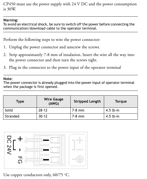
Wiring safety: Before connecting communication/download cables, power must be cut off to avoid electric shock; The power wiring requires the use of 60/75 ° C copper conductors, with a wire stripping length of 7-8mm and a torque of 4.5lb in.
3. Use and maintain safety
Safety function limitation: Emergency stop and other safety functions cannot be controlled through CP450 and require independent design of safety circuits;
Touch screen operation: Do not touch the screen/buttons with excessive force or sharp objects to prevent damage;
Maintenance power-off: The power must be disconnected before cleaning or maintenance, and only a soft cloth dipped in neutral detergent can be used to wipe the front panel during cleaning;
Battery replacement: Built in rechargeable lithium battery (for real-time clock), ABB recommended model should be used, incorrect replacement may cause explosion.
Hardware Parameters and Component Description
1. Key physical and electrical parameters
Parameter category specific specifications
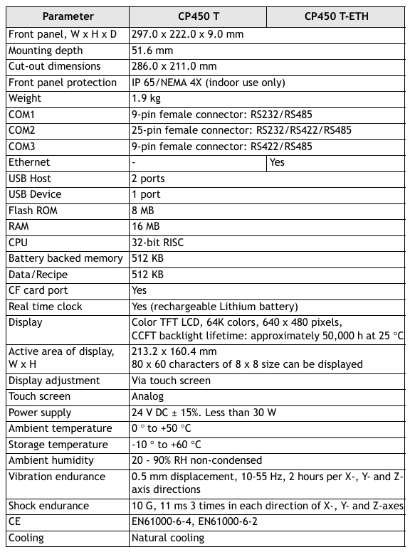
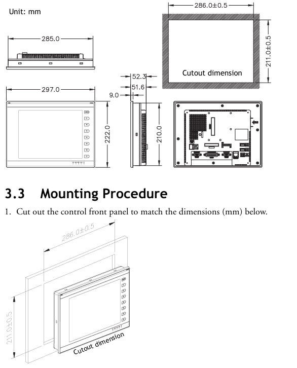
Size and Weight: Front Panel (W × H × D): 297.0 × 222.0 × 9.0mm; Installation Depth: 51.6mm; Hole Size: 286.0 × 211.0mm; Weight: 1.9kg
Storage and Memory Flash ROM 8MB, RAM 16MB, Battery Backup Memory 512KB (Data/Recipe Storage), CF Card Interface (Extended Storage)
32-bit RISC CPU with processor and clock; Real time clock (RTC, powered by lithium battery)
Environmental adaptability: working temperature of 0-50 ° C, storage temperature of -10-60 ° C; humidity of 20-90% RH (non condensing); Vibration tolerance (10~55Hz, 0.5mm displacement, 2 hours in each three-axis direction); Impact resistance (10G, 11ms, 3 times in each three-axis direction)
Certification standards CE certification (EN61000-6-4, EN61000-6-2)
2. Core component description (front/rear panel)
Front panel: includes fixed mounting holes, 8 function keys (1 menu key+7 F1~F7 keys), power indicator light, communication indicator light, network indicator light, 10.4-inch touch screen;
Rear panel: 24V DC power input interface, 3 communication ports (COM1~COM3), Ethernet interface, 2 USB host ports (for printer/USB flash drive), 1 USB device port (for data transmission), CF card interface, 12 bit DIP switch (for configuring working mode and communication parameters).
Installation process (including key steps)
1. Inspection of packaging list
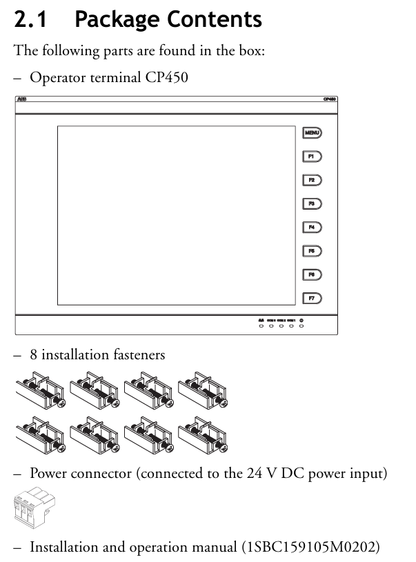
After unpacking, it is necessary to confirm that the following components are included. If they are missing, please contact the supplier:
1 CP450 operator terminal;
8 installation fasteners;
1 24V DC power connector (pre installed on the device);
One installation and operation manual (1SBC159105M0202).
2. Opening and fixing
Panel perforation: Drill holes on the control front panel according to the size (286.0 ± 0.5mm × 211.0mm), ensuring that the edges are flat and free of burrs;
Equipment embedding: Insert CP450 into the opening and fix it to the front panel with the built-in fasteners (screws) of the equipment, with a torque controlled at 0.6~0.7 Nm (5.31~6.2 lb in), to avoid uneven force that may cause deformation of the equipment;
Installation angle: The installation angle of the equipment should be within the range of 0~135 ° (based on the display screen) to ensure the operating field of view and heat dissipation effect.
3. Grounding and power wiring
Grounding operation: Connect the grounding cable from the power connector on the rear panel of the device to an independent grounding point, ensuring that the grounding resistance is ≤ 100 Ω;
Power wiring: After disconnecting the power supply, remove the screw of the power connector, insert the stripped 24V DC wire (positive and negative poles distinguished), tighten the screw, and plug it back into the device power input interface. Copper conductors must be used and meet the wire diameter requirements (refer to safety specification 2.3).
4. Wiring requirements
Communication cables should be routed separately from power cables to avoid electromagnetic interference;
All communication cables must use shielded cables to reduce the impact of noise.
DIP switch configuration (core function switching)
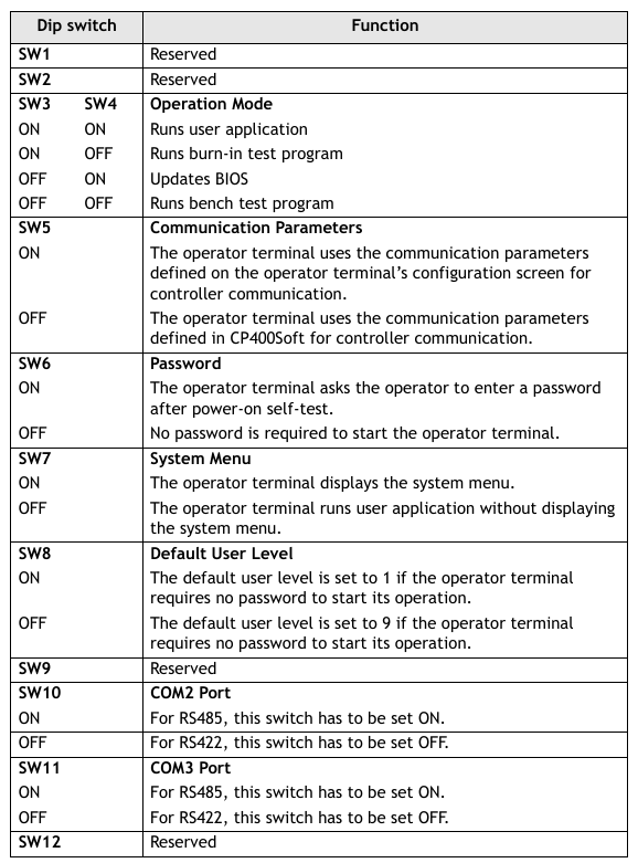
The 12 bit DIP switches (SW1-SW12) on the rear panel of CP450 are used to configure working modes, communication parameters, password requirements, etc. The key switch functions are shown in the table below (switches not labeled as "reserved" must be strictly set according to requirements):
Specific setting instructions for DIP switch function classification
SW3~SW4 working mode - ON+ON: run user applications; -ON+OFF: Run the aging test program; -OFF+ON: Update BIOS; -OFF+OFF: Run the bench test program
SW5 communication parameter source - ON: communication parameters defined using the device configuration interface; -OFF: Communication parameters defined using CP400Soft software
SW6 power on password requirement - ON: After the power on self-test, the password needs to be entered; -OFF: No password required for startup
SW7 system menu display - ON: After self-test, the system menu is displayed; -OFF: Run the user application directly without displaying the system menu
SW8 default user level - ON: When starting up without a password, the default user level is 1 (highest privilege); -OFF: Default level 9 (minimum permission)
SW10 COM2 port mode - ON: COM2 is in RS485 mode; -OFF: COM2 is in RS422 mode
SW11 COM3 port mode - ON: COM3 is in RS485 mode; -OFF: COM3 is in RS422 mode
SW1,2,9,12 retain no functionality, no need to set
Communication port configuration
CP450 provides three serial communication ports (COM1~COM3), one Ethernet port, and one USB port, supporting flexible connections with controllers and third-party devices. The key parameters are as follows:
1. Serial communication ports (COM1~COM3)
Port interface type supports protocol pin function (core) adaptation scenarios
COM1 9-pin female head RS232/RS485- RS485+(1 pin), RS485- (6 pins); -RS232 RXD (2-pin), TXD (3-pin), GND (5-pin) are connected to controllers (such as PLCs) and simple peripherals
COM2 25 pin female head RS232/RS422/RS485- RS485+/RS422 TX+(14 pins), RS485-/RS422 TX - (15 pins); -RS232 TXD (2-pin), RXD (3-pin) for connecting multiple devices and long-distance communication
COM3 9-pin female head RS422/RS485- RS485+/RS422 TX+(1 pin), RS485-/RS422 TX - (6 pins); -RS422 RX+(4-pin), RX - (9-pin) long-distance, high stability communication
Attention: The port mode needs to be matched with the DIP switch (if COM2 is RS485, set SW10=ON), otherwise communication will fail.
2. Other communication interfaces
Ethernet port: only supported by CP450 T-ETH model, used for high-speed network communication, suitable for industrial Ethernet scenarios;
USB interface: 2 USB host ports (for connecting printers and USB drives for data storage or printing), 1 USB device port (for connecting to a PC to transfer applications or recipes);
CF card interface: used for extended storage, can store application backup, recipe data, etc.
Core operational functions (including debugging and maintenance)
1. Self Test
After the device is powered on, it automatically performs hardware self-test and the screen displays the test results. The following items should be focused on:
Key detection contents: RAM, battery status, BIOS checksum, firmware checksum, application checksum, communication ports (COM1~COM3), real-time clock (RTC);
Fault handling: If a certain item displays "Failed", follow the prompts to troubleshoot (such as firmware/application verification failure requiring re download; communication port failure requiring checking wiring and DIP switch);
First use: The real-time clock (RTC) needs to be manually reset to ensure time synchronization.
2. System menu operation (SW7 needs to be set to ON)
After self checking, enter the system menu and provide 5 core functions that need to be operated through the touch screen or function keys:
System menu command function description
Link establishes communication connections between devices and external devices (such as PCs, other CP450s)
F2- Configure real-time clock (date, time) and communication parameters (baud rate, data bits, stop bits, etc.) using the directional keys to select fields and the ± key to adjust values
F3- Copy copies the application program of the current device to another CP450, requires connecting the download cable and entering the password
F4- Set calibration touch screen (touch the top left/bottom right corner and center of the screen), this operation will clear RAM data
F5- Run the user application and exit the system menu
3. Application download and upload
(1) Download the application (PC → CP450)
Hardware connection: Use TK401 cable to connect the RS232 port of the PC to COM1 of CP450, or use TK402 cable to connect COM2 (power-off wiring required);
Switch settings: Set SW7 to ON (display system menu), SW5 to be set according to the parameter source (set to ON on the device end and OFF on the software end);
Software operation: Open CP400Soft, load the application and compile it (modifications must be recompiled), select "Application/Download Firmware/Application" for the first download, and select "Application/Download Application" for subsequent downloads;
Progress monitoring: The screen displays "Programming application...", and after completion, press F5 Run to run the application.
(2) Upload application (CP450 → PC)
Connection and settings: Follow steps 1-2 of the download process to ensure that the communication parameters match;
Software operation: Select "File/Upload Application" in CP400Soft and save it as * AF6 file, enter the password set in CP400Soft (see 7.10);
File conversion: After uploading, you need to open the file through "File/Recreate Source" and save it as * V6F format, used for subsequent modifications and maintenance.
Attention: The application must be run once before the first upload, otherwise the upload function will be disabled.
4. Recipe upload/download
The formula is used to store production parameters (such as process settings), and the operation process is as follows:
Upload recipe: Set SW7 to ON, select "File/Upload Recipes" in CP400Soft, and save as * RCP file;
Download Recipe: Open the application containing the recipe in CP400Soft, select "File/Download Recipes", and choose * RCP file, run F5 Run after completion;
Prerequisite: The formula length and quantity must be defined in the application, and the existing formula format must be uploaded before editing a new formula.
5. Password management (4 scenarios)
CP450 supports multi-level password permissions to protect application and operational security. The key scenarios are as follows:
Password scene configuration method and permission instructions
The startup password (SW6=ON) is created in CP400Soft using the "Action Button" to create a password table. The registration password and user level (levels 1-9) are highest at level 1 (the password table can be modified) and lowest at level 9; You need to enter a password to start up, otherwise the application cannot run
During operation, use the "Action Button" to create a password keyboard button for permission switching. Press it and re-enter the password. Updating the user level can temporarily increase/decrease permissions (such as entering a high-level password for key functions)
Button password protection: Set permission levels for buttons (such as Goto Screen) in CP400Soft. Users with lower levels need to enter a password to restrict access to key functions (such as parameter modification and system settings)
When setting the password for copying/uploading applications (F3 Copy) or uploading applications (File/Upload Application) on the "Application/Workstation Setup" ->"Password" tab of CP400Soft, this password is required
- OMRON
- ABB
- General Electric
- EMERSON
- Honeywell
- HIMA
- ALSTOM
- Rolls-Royce
- MOTOROLA
- Rockwell
- Siemens
- Woodward
- YOKOGAWA
- FOXBORO
- KOLLMORGEN
- MOOG
- KB
- YAMAHA
- BENDER
- TEKTRONIX
- Westinghouse
- AMAT
- AB
- XYCOM
- Yaskawa
- B&R
- Schneider
- KONGSBERG
- NI
- WATLOW
- ProSoft
- SEW
- ADVANCED
- Reliance
- TRICONEX
- METSO
- MAN
- Advantest
- STUDER
- DANAHER MOTION
- Bently
- Galil
- EATON
- MOLEX
- DEIF
- B&W
- ZYGO
- Aerotech
- DANFOSS
- Beijer
- Moxa
- Rexroth
- Johnson
- WAGO
- TOSHIBA
- BMCM
- SMC
- HITACHI
- HIRSCHMANN
- Application field
- XP POWER
- CTI
- TRICON
- STOBER
- Thinklogical
- Horner Automation
- Meggitt
- Fanuc
- Baldor
- SHINKAWA
- Other Brands
- UniOP
- KUKA
- Iba
- Beckhoff
- ADLINK
-
 Rolls-Royce R02TCN-E0L3-00 Remote Controller Features
 -
 Etel SA-IL 03-208 Linear Motor Section
 -
ETEL ILM03-060-3RA-A00 Ironless Linear Servo Motor
-
 ETEL DSCDP321-121-000 Dual Position Controller Board
 -
 Etel DSCDP121-111F-000A Dual Axis Servo Drive
 -
 Etel EA-S0M-400-40/80A-0000-00 AccurET Modular Power Supply
 -
 Etel TMB+0291-150-RO-00000-0A0 Rotor
 -
 ETEL DSCDP131-111F-000A Position Controller
 -
 ETEL DSC2P154-421F-000A Servo Drive
 -
 ETEL DSO-SER211-000 Add-On Power Board for Servo Amplifier
 -
 ETEL 613712-05 4-Axis Control Assembly
 -
 ETEL P2M-300-07/15A Accuret Position Controller
 -
 ETEL LMP07-100-3TAS-229 Motor Ruler Primary Part
 -
 ETEL 569866-03 ASME-RTMA014 Motor
 -
 ETEL DSCDP131-111-000 Dual Position Controller
 -
 ETEL DSB2S134-211E-000H Digital Servo Amplifier
 -
 ETEL DSCDP121-111F-000A DSC Dual Controller
 -
 ETEL DSC2P154-421E-000A Servo Drive
 -
 ETEL DSCDP121-111C-000A Regulator – Stable Power Control
 -
 ETEL DSC2P131-111B-000D Driver Board
 -
 ETEL ILM03-060-3RA-A00 Linear Motor
 -
 ETEL EA-S0M-300-40/80A-0090-00 Power Supply Module
 -
 Etel DSCDP131-111-000 Position Controller
 -
 ETEL DSC2P121-111E-001A Digital Servo Amplifier
 -
ETEL DSB2P101-121E-009H Position Controller
-
 ETEL IWM040-0128-00 Ironcore Linear Motor Magnetic Way
 -
 ETEL AccurET EA-S0M-400-40/80A-0000-00 Modular Power Supply
 -
ETEL LMC11-050-3TA-S10C Motion Controller
-
 ETEL LMC11-050-3TA-250A Controller Module
 -
 ETEL DSB2P101-121E-009H Digital Servo Amplifier Position Controller
 -
 ETEL AccurET Modular 400 Position Controller
 -
 ETEL DSA2 Digital Servo Amplifier
 -
ETEL DSC2P154-421-000 Servo Drive
-
 ETEL DSO-PWS121-003 Power Supply Module
 -
 ETEL 0348M-070-02D-004 Linear Encoder
 -
 ETEL DSC2P131-111-000 Linear Servo Amplifier – 10Arms/30Arms
 -
ETEL DSC2P131-121-000 Digital Servo Amplifier
-
ETEL DSB2P131-111E-000H Digital Servo Amplifier
-
ETEL DSO-PWS111-000 Power Supply Module
-
ETEL LMC11-050-3TA-S41C Linear Motor Module – High Thrust Density
-
 ETEL EA-P2M-300-07/15A Drive Specs
 -
 ETEL DSO-RAC200A-011D Dual Position Controller Rack
 -
 ETEL Short-Stroke Actuator ID809786-03
 -
 ETEL DSCDM332-111-000 Servo Controller Specs
 -
 ETEL DSCDL332-131-000A Position Controller
 -
 ETEL LMP07-100-3TAS-229 Linear Motor
 -
ETEL LMA11-120-3ZA-359C Linear Motor
-
ETEL DSA2S211ZA-018A Digital Servo Amplifier
-
 ETEL EA-P2M-300-07/15A AccurET Controller
 -
ETEL LMB06-050-2QA-239B Linear Motor Guide
-
 ETEL DSCDP334‑421‑000 Servo Drive – High‑Power Digital Controller Positioner
 -
ETEL DSCDP121‑111E‑000A Dual Driver Board – High‑Density Motion Control Module
-
 ETEL DSA2 S1B22A Digital Servo Amplifier – High‑Efficiency Drive for Industrial Motors
 -
 ETEL DSCDM342‑111‑000 Servo Amplifier – Multi‑Axis Digital Drive
 -
ETEL MWA120‑0512‑00B 512mm Linear Motor Magnet
-
ETEL EA‑P2M‑300‑07/15A‑0100‑01 AccurET Modular Position Controller – Medium‑Power Drive
-
Etel DSC2P141‑111‑000 568425‑01 Digital Servo Amplifier – Compact High‑Performance Drive
-
 Etel EA‑P2M‑400‑10/20A‑0000‑01 AccurET Modular Position Controller – High‑Voltage Drive
 -
ETEL DSC2P142‑111‑000 Digital Servo Amplifier – Compact Position Controller
-
ETEL DSDH153‑121C‑001D Digital Servo Drive – High‑Power Motion Control
-
ETEL DSB2P131 & DSO-CAN111A Servo Amplifier Set
-
ETEL DSA2S211ZA-018A Digital Servo Amplifier
-
ETEL DSMAX212-111-001 568540-01 DSMAX2 Servo Controller
-
 ETEL TMB+0291-150 Torque Motor Stator Assembly
 -
 ETEL EA-S0M-300-40/80A AccurET PSU
 -
ETEL DSO-PWR112C-000B Power Supply Module
-
ETEL DSC2P141-111-000 Linear Servo Amplifier
-
ETEL DSB2S154-211-000H Servo Amplifier
-
ETEL DSCDP121-122-000 Digital Controller
-
ETEL DSCDP121-111E-000A Dual Position Controller
-
ETEL DSCDM332-111-000 Linear Servo Controller
-
 ETEL DSB2P134-111E-000H Servo Amplifier
 -
ETEL DSCDP132-111-000 Control Board Guide
-
 ETEL DSB2S154-211E-000H Servo Amplifier
 -
ETEL EA-SOM-300-40/80A Power Supply Module
-
ETEL ILM12-060-3PD-R20C Linear Motor with IWM Ways
-
 ETEL P2M-300-07 AccurET Position Controller
 -
ETEL DSB2P124-111E-000H Servo Amplifier
-
 ETEL EA-P2M-048-05/10A Position Controller
 -
 ETEL EA-S0M-300-40/80A Power Supply Module
 -
ETEL MWA070-0256-20B Linear Motor Magnet Guide
-
ETEL MWD070‑0128‑21A Linear Motor – Compact Ironless Linear Motor for High‑Speed Precision
-
ETEL DSB2P124‑211E‑000H Digital Servo Amplifier – 300 VDC Slave Drive for High‑Voltage Systems
-
ETEL MWD100‑0128‑00B Linear Motor – High‑Force Ironless Linear Motor for Precision Motion
-
ETEL AccurET EA‑S0M‑400 & P2M‑400‑05/10A Drive Module
-
ETEL EA‑S0M‑400‑40/80A‑0000‑00 AccurET Power Supply – High‑Power DC Supply for Motion Systems
-
ETEL MWA050‑0128‑20B Linear Motor Magnet – High‑Force Magnet Assembly for Linear Motors
-
ETEL DSB2S121‑111E‑000H Digital Servo Amplifier – High‑Current Drive for Demanding Motion
-
 ETEL DSCDM332‑111C‑000B Digital Position Controller DSCDM – High‑Density Motion Module
 -
ETEL EA‑P2M‑048‑2.5/5A‑0100‑01 AccurET Modular Position Controller
-
 ETEL DSC2P121-111E-001A Digital Servo Controller – High‑Precision Motion Control
 -
ETEL MWA050-0128-20B Linear Motor Magnet
-
 ETEL DSB2P142-111E-000H Drive Specs
 -
 ETEL DSB2S234-111E-000H Servo Amplifier
 -
 ETEL EA-P2A-400-10-20A Position Controller
 -
ETEL DSB2 Digital Servo Amplifier Controller DSB2P142-111E-000H SN 014661437
-
ETEL EA-S0M-400-40/80A-0000-00 AccurET Power Supply Module 650140-01
-
ETEL DSB2P131-111E-000H Servo Amplifier
-
ETEL EA-P2M-400-10/20A AccurET Controller
-
ETEL DSDP324-322F-000C Dual Motor Driver
-
ETEL DSB2S154-211E-000H Digital Servo Amplifier Drive
-
ETEL DSO-PWS111B-000C Power Supply Board 1130E-070-018
-
ETEL DSCDP324-322G-000A Servo Amplifier
-
ETEL DSB2P142-111E-000H Servo Amplifier Drive
-
 ETEL EA-P2M-400-15/40A & EA-S0M-400 Drive Set
 -
ETEL DSB2P142-111E-000H Digital Servo Amplifier
-
ETEL LMG15-070-3QC-H11 Linear Motor
-
 ETEL TMA0140-070-3RB-S62B Torque Motor
 -
ETEL DSA2S211ZA Digital Servo Amplifier
-
ETEL AccurET EA-P2M-300-4/7.5A-0100-01 Modular Position Controller
-
 ETEL DSCDL332-131C-000A Servo Control Board
 -
ETEL DSCDP324-322F-000C Dual Motor Driver
-
 ETEL EA-P2M-400-10/20A Position Controller
 -
ETEL DSC2P121 and DSO-HIO33 Servo Amplifier Set
-
 ETEL EA-P2M-400-15/40A AccurET Drive
 -
ETEL EA-P2M-300-07/15A Position Controller
-
ETEL EA-P2M-048-05/10A-0100-01 Servo Drive
-
 ETEL EA-S0M-300-40/80A Servo Drive Guide
 -
ETEL DSB2P131-111E-000H Digital Servo Amplifier
-
ETEL DSCDP334-421-000 Servo Drive Guide
-
ETEL EA-S0M-300-40 80A-0000-00 Motion Control Module
-
 ETEL UltimET Light Motion Controller EU-LGP-0-0-1000-01 Multi-Axis
 -
 ETEL DSO-RAC601-029 Controller Rack
 -
ETEL DSMAX212-121C-000C Board
-
 ETEL DSCDL132-212B-000C Position Controller
 -
ETEL TMB0291-050-3TDS-E82 Torque Motor
-
 ETEL DSMAX212-121-000 Board
 -
ETEL DSB2P131-111E-000H Digital Servo Controller Amplifier Unit


