
How to install and operate KBAC series adjustable frequency drive?
How to install and operate KBAC series adjustable frequency drive?
Product Overview
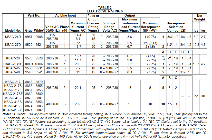
The KBAC series adjustable frequency drive is suitable for three-phase AC motors and has a NEMA 4X/IP65 protection level. It can achieve waterproof and dustproof performance and is suitable for indoor and outdoor flushing environments. Supports voltages of 208-230V and 400/460V, with a frequency of 50/60Hz, capable of driving motors ranging from sub fractional horsepower to 10 horsepower. It also has variable speed, soft start function, and electronic motor overload protection. It is compatible with AC inputs of 115V, 208/230V, and 400/460V, and is available in 2G and 3G models. Some 3G models have product labels labeled "(3G)", and both KBAC-217 and 416 series are 3G models.
Core functions and features
(1) Standard Features
Shell: Industrial grade die cast aluminum shell with hinged cover, available in two surface treatments: dark gray and FDA approved white.
Convenience of operation: No programming required, adjustable potentiometer and jumper settings can be made, and most application scenarios are pre-set at the factory.
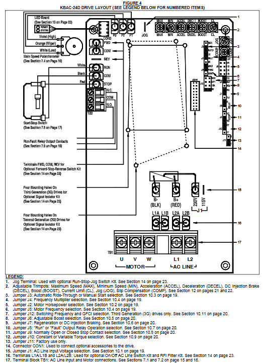
Selection function: including motor horsepower selection jumper (J2), switch frequency and GFCI selection jumper (J12, only 3G model), diagnostic LED light (power and status indication), operation/fault relay output contact, start stop switch, barrier terminal block, etc. The driver output frequency can also be selected through jumper to achieve a maximum motor speed of twice the rated speed, with power-off recovery function and zero speed holding torque, as well as multiple adjustable fine adjustment potentiometers.
Jumper selection: covering AC input voltage (only J1 for KBAC-24D and 27D), motor horsepower (J2), automatic power-off recovery/manual start (J3), frequency multiplier (J4), motor frequency (J5), fixed/adjustable boost (J6), regeneration/injection braking (J7), operation/fault output relay operation (J8), normally open/normally closed stop contact (J9), constant torque/variable torque (J10), switching frequency and GFCI (only J12 for 3G models).
(2) Performance characteristics
Power Start ™: Can provide over 200% starting torque to ensure smooth start-up under high friction loads.
Slip compensation: With static automatic tuning and boost function, it achieves excellent load regulation over a wide speed range.
Speed range: The speed ratio can reach 60:1.
(3) Protection features
Motor Overload Protection (I2t): With RMS current limitation, it can prevent motor burnout, avoid false tripping, and is certified by UL as an electronic overload protector for motors.
Electronic Surge Current Limitation (EICL) ™): Eliminate harmful AC input surge currents during startup.
Other protections: equipped with short-circuit protection (shutdown in case of motor phase to phase short circuit), regenerative protection (to avoid tripping caused by high bus voltage due to rapid deceleration of high inertia load), overvoltage and undervoltage protection (shutdown in case of input voltage exceeding the range), MOV input transient suppression (to protect driver components from damage caused by input voltage spikes), and microcontroller self-monitoring and automatic restart functions.
Installation points
(1) Installation method
It is recommended to install it vertically on a flat surface to ensure sufficient ventilation, and reserve enough space below for wiring. If installed inside the casing, it is necessary to ensure that the casing size is sufficient for heat dissipation, the ambient temperature does not exceed 40 ° C (104 ° F), and it cannot be used in explosion-proof environments. The installation must be firm.
(2) Communication input circuit breaker
The driver does not have a built-in circuit fuse, and a fuse (such as Littelfuse 312/314, Bus ABC, or equivalent) or circuit breaker must be connected in series with each non grounded wire according to electrical specifications. The neutral wire or grounding wire should not be blown. Please refer to Table 2 (page 7) for specific fuse specifications.
(3) Electrical connection
Wiring specifications: It must comply with the National Electrical Code and applicable local regulations. Wiring should be carried out after power failure to ensure correct grounding. When remotely connecting potentiometers, switches, etc., it is recommended to install signal isolators to avoid high voltage risks.
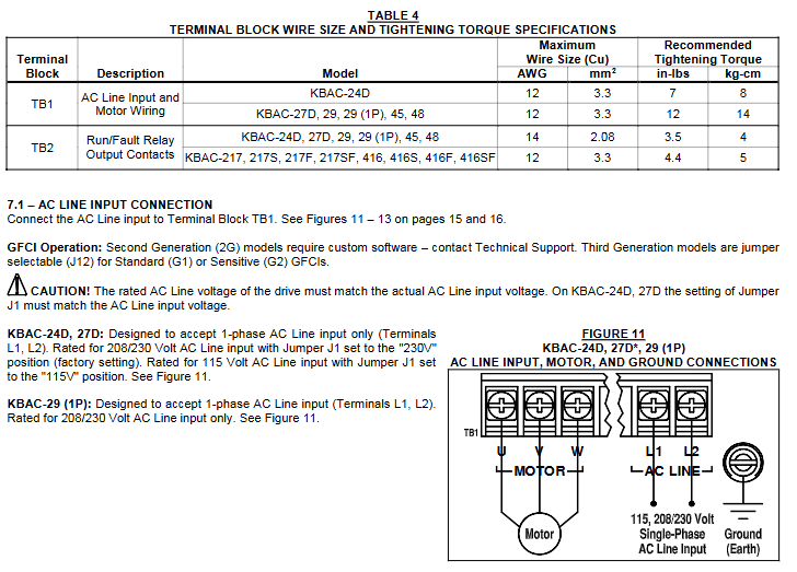
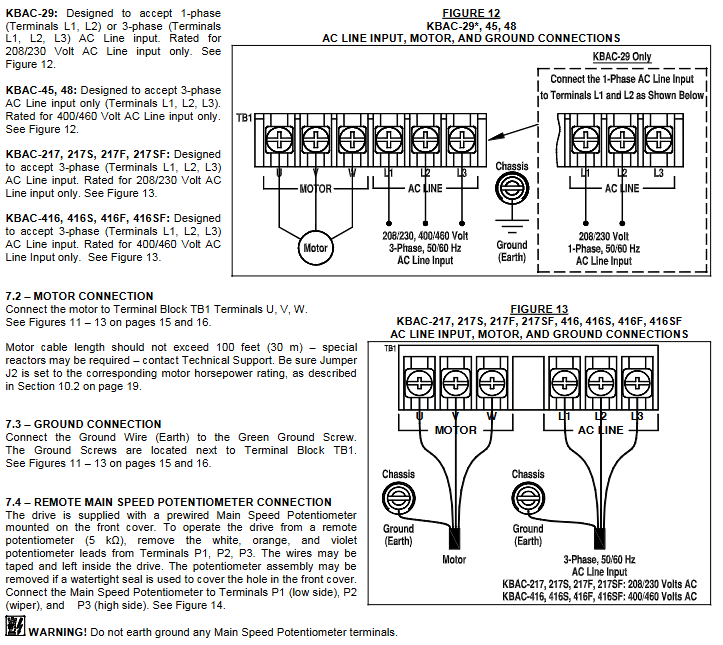
Communication input connection: The wiring terminals of different models of drivers are different, and they need to be connected according to the model. The rated AC input voltage of the driver needs to match the actual input voltage, and some models need to set corresponding jumper wires.
Motor connection: The motor is connected to the U, V, and W terminals of TB1. The length of the motor cable should not exceed 100 feet (30 meters). If it exceeds this, a special reactor is required (technical support should be contacted), and the J2 jumper should be set to the corresponding motor horsepower level.
Grounding connection: The grounding wire (earth) should be connected to the green grounding screw, and the motor should also be properly grounded.
Other connections: including remote main speed potentiometer, remote start stop switch, automatic restart (requiring cancellation of start stop switch and hard wiring), voltage following (0-5V DC analog signal that needs to be isolated), enable circuit, operation/fault relay, etc., all have specific wiring methods and precautions.
(4) Bus capacitor repair
If the drive is stored for more than one year, it is necessary to apply AC input voltage in shutdown mode for at least 1 hour to repair the power bus capacitor, otherwise the capacitor may be damaged.
Operation and Debugging
(1) Start the program
After completing the jumper and fine adjustment potentiometer settings and wiring, connect the AC power supply, and the power (PWR) LED green light will turn on. Use the start stop switch to briefly place it in the "start" position to start the driver, and the motor will accelerate to the set speed. If the motor turns in the wrong direction, replace any two motor leads after powering off.
(2) Restart after malfunction
Drive monitoring includes five types of faults: undervoltage, overvoltage, motor short circuit, overload, and phase loss. After the faults are cleared, restart through the start stop switch; If the start stop switch is cancelled, the AC power supply needs to be disconnected and reconnected to restart. Partial faults (such as overvoltage) can be automatically restarted after the voltage returns to normal in automatic power-off recovery mode.
(3) Fine tuning potentiometer adjustment
Minimum speed (MIN): Factory set to 0% of the frequency setting, clockwise rotation can increase the minimum speed.
Maximum speed (MAX): Factory set to 100% of the frequency setting, counterclockwise/clockwise rotation can reduce/increase the maximum speed.
Acceleration (ACCEL): The factory setting is 1.5 seconds. Clockwise/counterclockwise rotation extends/shortens the acceleration time, and rapid acceleration may trigger the current limiting circuit to extend the acceleration time.
Decel: The factory setting is 1.5 seconds, and clockwise/counterclockwise rotation extends/shortens the deceleration time. In high inertia load applications, the deceleration time may be automatically extended. It is recommended to set the acceleration and deceleration time to 10 seconds or more for high inertia loads.
DECEL (Direct Current Injection Braking): Only when J7 is set to "INJ", this potentiometer is used to set the time for direct current to be applied to the motor. It is factory set to regenerative braking (J7 is set to "RG").
Slip Compensation (COMP): Factory set to 1.5 volts per hertz, clockwise/counterclockwise rotation increases/decreases slip compensation, and can be adjusted through specific steps to achieve speed stability under different loads.
Motor overload (I2t) and RMS current limit (CL): The factory setting is 160% of the rated current of the driver. Clockwise/counterclockwise rotation increases/decreases the current limit, which needs to be adjusted step by step and cannot exceed the rated current of the motor by 160% to avoid motor overheating.
Boost (BOOST): The factory setting is a fixed boost (J6 is set to "FIX"), which can be adjusted when J6 is set to "ADJ". It operates in the frequency range of 0-15Hz and needs to be adjusted step by step to avoid overheating and damage to the motor winding caused by excessive boost.
Jog: An optional run stop jog switch kit is required, which can set the jog speed. When the switch is in the "jog" position, the speed is set by the fine adjustment potentiometer, and when in the "run" position, the speed is set by the main speed potentiometer.
Diagnosis and fault handling
(1) Diagnostic LED
Power LED (PWR): When the AC power is turned on, the green light will turn on. It should not be used as a basis for power outage. Before maintenance, make sure that the main power switch or circuit breaker is disconnected.
Status LED (ST): It is a three color LED with different flashing frequencies and colors corresponding to different operating states and faults, such as normal operation (green light flashing slowly), overload (red light constantly on when 120% -160% full load; red light flashing rapidly when timeout trips), short circuit (red light flashing slowly), undervoltage (red and yellow light flashing rapidly), overvoltage (red and yellow light flashing slowly), stop (yellow light constantly on), standby (yellow light flashing slowly, only when installing forward and reverse switches), input phase loss (yellow light flashing rapidly, specific models), overheating trip (red and yellow light flashing rapidly, specific models), and the status will change accordingly after troubleshooting.
(2) Common fault handling
Overload fault: After clearing the fault, restart and check the motor current with an AC RMS ammeter. If the current limit is set too low, adjust it.
Overvoltage fault: In automatic power-off recovery mode, the driver automatically restarts after the voltage returns to normal.
Motor steering error: replace any two motor leads after powering off.
Other faults: troubleshoot according to the status LED indication, such as checking the motor wiring for short circuits, checking the input voltage for undervoltage/overvoltage, checking the input circuit for phase loss (specific model), and checking the heat dissipation for overheating (specific model).
Optional accessories
We offer a variety of optional accessories, including forward and reverse switch kits, AC line on/off switch kits, run stop jog switch kits, SIAC-PS signal isolator kits (available in 3G and 2G models), automatic/manual switch kits, SIAC-PS signal isolator and automatic/manual switch combination kits, AC line filter kits (available with "S" and "NS" suffixes, some models pre installed at the factory), liquid tight joint kits, etc. Different accessories are suitable for different models of drivers, and some accessories require specific installation methods to ensure liquid tightness or achieve corresponding functions.
Main product models
Basic model: KBAC-24D、KBAC-27D、KBAC-29、KBAC-29 (1P)、KBAC-45、KBAC-48、KBAC-217、KBAC-217S、KBAC-217F、KBAC-217SF、KBAC-416、KBAC-416S、KBAC-416F、KBAC-416SF, These models cover both 2G and 3G categories, among which the KBAC-217 series (including KBAC-217, 217S, 217F, 217SF) and the KBAC-416 series (including KBAC-416, 416S, 416F, 416SF) are both 3G models, KBAC-24D、27D、29、29 (1P)、 The 3G models of 45 and 48 will be labeled with "(3G)" on the product label.
Model classification basis:
Voltage adaptation: KBAC-24D, 27D, 29, 29 (1P), 217 series are compatible with 208/230V voltage, KBAC-45、 The 48 and 416 series are compatible with 400/460V voltage.
According to input phase: KBAC-24D, 27D, 29 (1P) only support single-phase input, while KBAC-29 can support single-phase or three-phase input, KBAC-45、 The 48, 217, and 416 series only support three-phase input.
- OMRON
- ABB
- General Electric
- EMERSON
- Honeywell
- HIMA
- ALSTOM
- Rolls-Royce
- MOTOROLA
- Rockwell
- Siemens
- Woodward
- YOKOGAWA
- FOXBORO
- KOLLMORGEN
- MOOG
- KB
- YAMAHA
- BENDER
- TEKTRONIX
- Westinghouse
- AMAT
- AB
- XYCOM
- Yaskawa
- B&R
- Schneider
- KONGSBERG
- NI
- WATLOW
- ProSoft
- SEW
- ADVANCED
- Reliance
- TRICONEX
- METSO
- MAN
- Advantest
- STUDER
- DANAHER MOTION
- Bently
- Galil
- EATON
- MOLEX
- DEIF
- B&W
- ZYGO
- Aerotech
- DANFOSS
- Beijer
- Moxa
- Rexroth
- Johnson
- WAGO
- TOSHIBA
- BMCM
- SMC
- HITACHI
- HIRSCHMANN
- Application field
- XP POWER
- CTI
- TRICON
- STOBER
- Thinklogical
- Horner Automation
- Meggitt
- Fanuc
- Baldor
- SHINKAWA
- Other Brands
- UniOP
- KUKA
- Iba
- Beckhoff
- ADLINK
-
 VMIVME-9081 Intelligent I/O Controller
 -
 VMIC VME-2128 Digital Output Board
 -
 VMIC VMIOMAX-2940A PLC Module
 -
 VMIC VMIVME-5530M Optical Extender Board
 -
 VMIC VMIVME-7588-787 SBC – VMEbus Single Board Computer
 -
 VMIC VMIOMAX-1640B PLC Module
 -
VMIC VMIPCI 5588-101 Reflective Memory Board
-
 VMIVME-7765 VME Board – Industrial Control
 -
 GE Abaco VMIVME-7807 VME Processor Board
 -
 VMIC VMIVME-2540 Digital I/O Board
 -
 VMIC VMIACC BT01 Adapter Calibration Module
 -
 Maxsys Technology VMIC Test Station 00465-3800
 -
 VMIC VMIVME-1101 32-Bit TTL Digital Input Board
 -
 VMIVME-4120 VME Circuit Board
 -
FANUC VMIC 332-999995-000 D VME Bus Board
-
 VMIC VMIVME-7455 VME IDE CD-ROM Drive Module
 -
 VMIC VME I/O Board 5620
 -
 VMIC VME I/O Board 2128
 -
 VMIC VMIVME7588 VME Processor Board
 -
 GE Fanuc VMIVME-3419-200 Signal Conditioning Module
 -
 VMIC VMIVME 4512 Analog I/O Board
 -
 GE Fanuc VMIC VME 6U 6-Slot Chassis
 -
VMIC VMIVME 5504 VMEbus Slave Module
-
 VMIC VMIOMAX-9102A Power Supply
 -
 VMIC VMIVME 3120 Board
 -
VMIC VMIVME-2330 VMEbus Circuit Board
-
 VMIC VMIPMC-5565 Reflective Memory Node PMC
 -
 GE Fanuc VMIVME-7671 Linux Controller Processor
 -
 VMIC VMIVME-5599 Fiber Optic Switch
 -
 GE Fanuc VMIVME-4120 16-Ch 12-Bit Analog Output Board
 -
 VMIC VMIVME-4900 Dual Channel Synchro/Resolver Converter
 -
VMIC VMIVME4514A VME Interface Board
-
 VMI VME VMIC 4941 VME Interface Board
 -
 GE DS3820VMIC1A1B VME Interface Board
 -
 FANUC VMIVME7592-934 VME Processor Board
 -
 Abaco VMIC 5522V SGI-to-VME Bus Adapter Board
 -
VMIC VMIVME-4120 VME Circuit Board
-
 VMIVME7751 VME Single Board Computer
 -
 VMIC VMIVME5565 VME Reflective Memory Interface Board
 -
 VMIC VMIVME-4512 VME Processor Board
 -
 VMIC VMIVME-7454 VMEbus Analog Output Board
 -
 FANUC VMIVME-7452 Analog I/O Board
 -
 FANUC VMIVME-3230 Digital I/O Board
 -
 FANUC VMIVME-3114 Analog Input Board
 -
 FANUC VMIVME-2536 Digital I/O Board
 -
 VMIC 332-003413-111 C VMEbus Circuit Board
 -
 GE Fanuc VMIVME-7486 VMEbus CPU Processor Controller
 -
 VMIC VMIVME 4100 8-Channel 12-Bit DAC Board
 -
 VMIC VMIVME-4514 Module
 -
 VMIC VMIVME 1128 Digital Input Board
 -
GE Fanuc VMIVME-5588 High-speed Reflective Memory Board
-
 VMIC VMIVME-5565 Reflective Memory Board
 -
VMIC VMIVME-2127 Voltage Source Digital Output Board
-
VMIC VMIVME 4512 Analog VME Process PCB Assembly
-
 GE Fanuc VMIVME-3122-022 Analog I/O Module
 -
 VMIC VMIVME 5576 High Speed Fiberoptic Network Board
 -
 FANUC VMIVME-7452 VMEbus Analog I/O Board
 -
 FANUC VMIVME-2210 VMEbus Digital Output Board
 -
 FANUC VMIVME-7750-734000 VMEbus Single Board Computer
 -
 VMIC VMIVME 2210 VMEbus DO 28V Digital Output Board
 -
 VMIC VMIVME DR11W VMEbus DMA Interface Module
 -
 VMIC VMIVME-2536-200 5V Optically Coupled Digital I/O Board
 -
 VMIC VME-7754 VMIVMF7754-259000 VMEbus Control Card
 -
 VMIC 2170A VME Interface Board
 -
 GE VMIC PMC-5565PIORC-210000 Reflective Memory PMC Node Card
 -
 VMIC VMIVME-7750-750000 VME Single Board Computer
 -
 VMIC VMIVME-7751 VME Single Board Computer
 -
 VMIC 332-004512 Analog VME Process Board
 -
 VMIC VMIVME2528 VME Interface Board
 -
FANUC VMIVME-2120 VME Bus Interface Board
-
 FANUC VMIVME-2540 VME Bus Interface Board
 -
 FANUC VMIVME-3230 VME Bus Interface Board
 -
 FANUC VMIVME-4514 VME Bus Interface Board
 -
 ETEL DSB2S154-211E-000H Servo Amplifier
 -
 ETEL DSCQT112-111-000 Motion Control Module
 -
 ETEL LMG20-050-3QB-211A Servo Motor – High Torque Linear
 -
 ETEL EU-LCP-0-0-1000-01 Communication Card
 -
 ETEL DSA2P174ZA-033A Servo Amplifier Driver
 -
 ETEL EA-P2M-400-15/40A-0100-00 Servo Driver
 -
 ETEL DSC2P152-111-000 Servo Drive Amplifier
 -
 ETEL LMS15-050-3UA-209A Linear Motor
 -
ETEL DSC2P152-111D-000A Controller
-
 ETEL DSB2P131-111E-000B Digital Servo Amplifier Position Controller
 -
 ETEL DSO-PWR111C-000B Power Supply Module
 -
 ETEL DSCDP324-321F-000C Servo Driver
 -
 ETEL DSC2P152-111B-000D Controller
 -
 ETEL DSB2P142-111E-000H Circuit Board
 -
 ETEL LMG05-030-3QA-H01 Linear Motor
 -
 ETEL DSC2P152-111F-000A Controller
 -
 ETEL DSA2S211ZA Servo Drive
 -
 ETEL DSCDM332-112-000 Drive Module
 -
 ETEL DSCDP334-421-000 Digital Position Controller Servo Drive
 -
ETEL EA-P2M-400-15/40A-0100-00 AccurET Servo Drive
-
 ETEL TMA0140-050-3UB-202B Torque Motor
 -
 ETEL DSA1DL1D.PCB Servo Drive Board
 -
 ETEL DSA2DL 1A Servo Drive
 -
 ETEL DSMAX111B-000B Servo Drive
 -
ETEL DSO-PWS111C-000B Power Supply Module
-
 ETEL DSC2P142-111B-000D Servo Drive Amplifier
 -
 ETEL DSC2P132-111D-000A Servo Drive Amplifier
 -
ETEL DSC2P152-111B-000D Servo Drive Amplifier
-
ETEL DSB2P131-121E-000H Servo Drive Amplifier
-
 ETEL DSB2P142-111E-000H Servo Drive Amplifier
 -
ETEL DSO-PWR112C-000A Power Supply Module – High Power
-
ETEL DSO-PWR111C-000A Power Supply Module
-
ETEL DSB2P121-121E-000H Servo Drive Amplifier
-
 ETEL DSB2S134-111E-000H Digital Servo Amplifier
 -
 ETEL RTMA0140-070-AQN-21E Motor
 -
ETEL DSCDP132-111-000 Dual Controller Circuit Board – Motion Control
-
 ETEL LMS15-050-3UA-209Aft Linear Motor
 -
 ETEL DSCDP324-322G-000A Position Controller
 -
ETEL DSA2P174ZA-033A Servo Amplifier Driver
-
 ETEL DSA2P174ZA-017A Servo Amplifier Driver
 -
 ETEL LMD10-050-3QA-223A Linear Motor
 -
ETEL EU-LGP-0-0-1000-00 PCI Network Card
-
ETEL DSO-PWS111C-000B Power Supply Module
-
ETEL DSC2V174-111C-001A Servo Controller
-
 ETEL EA-P2M-600-15/40A-0000-01 AccurET Modular Position Controller
 -
 ETEL RTMA0140-070-AQN-21B DD Motor
 -
 ETEL DSC2P144-421-000 Servo Driver
 -
ETEL EA-P2M-400-15-40A-0100-00 Servo Drive
-
ETEL DSCDM341-111C-000B Board
-
 ETEL LMD10-050-3QA-223A Motor
 -
ETEL RTMA0140-070-AQN-21E DD Motor
-
 ETEL DSCDM342-111-000 Servo Variator
 -
ETEL DSC2P152-111E-000A Servo Amplifier
-
ETEL LMS15-050-3UA-209A Motor
-
ETEL RTMA0140-070-AQN-21C DD Motor – High Torque Direct Drive


