
GE VME-3122A High Performance 16 Bit Analog to Digital Converter (ADC)
GE VME-3122A High Performance 16 Bit Analog to Digital Converter (ADC)
Basic Information
Product Name: VME-3122A High Performance 16 Bit Analog to Digital Converter (ADC) Board
Production company: GE Fanuc Intelligent Platforms
Main features
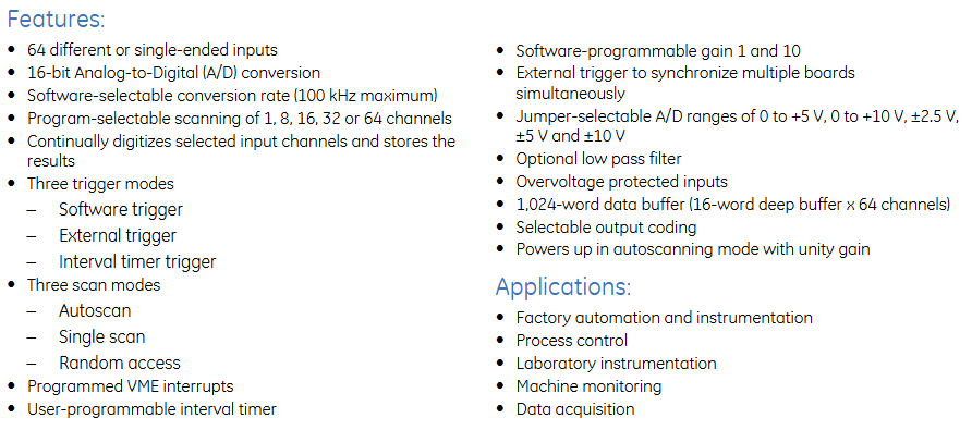
64 different or single ended inputs
16 bit analog-to-digital (A/D) conversion
Software selectable conversion rate (maximum 100kHz)
Programmable options for scanning channels 1, 8, 16, 32, or 64
Continuously digitize the selected input channel and store the results
Three triggering modes: software triggering, external triggering, and interval timer triggering
Three scanning modes: automatic scanning, single scan, and random access
Programmable VME interrupt
User programmable interval timer
Software programmable gains 1 and 10
External triggering can synchronize multiple boards simultaneously
Jumper selectable A/D range: 0 to+5V, 0 to+10V, ± 2.5V, ± 5V, and ± 10V
Optional low-pass filter
Over voltage protect
1024 word data buffer (16 word deep buffer x 64 channels)
Optional output encoding
When powered on, it is in automatic scanning mode with a gain of 1
Application Fields
Factory automation and instrumentation
process control
laboratory instruments
Machine monitoring
data acquisition
Ordering Options
Option Description
A (input filter option) 0=no filter; 1=10Hz(-3dB); 2=50Hz(-3dB); 3=100Hz(-3dB); 4=500Hz(-3dB)
B (channel quantity option) 0=64 channels high performance; 1=32 channels high performance; 2=16 channels high performance
C (input option) 0=differential analog input channel with 96 pin non latch connector; 1=Single ended analog input channel with 96 pin non latch connector; 2=Differential analog input channel with 64 pin latch connector; 3=Single ended analog input channel with 64 pin latch connector
DE 0 (reserved for future options)
F (Special Sales Order) 0=Standard VME front panel without conforming coating; 1=Reserved; 2=Standard VME front panel with conforming coating
Connector data
Recommended style for connecting components P3 and P4 I/O connectors
64 pin IDC mating connector (64 pin) Panduit 120-964-435
Strain relief (applicable to 64 pin connectors) Panduit 100-000-072
96 pin discrete mating connector (96 pin discrete) AMP 925486-1
Female crimping contact (96 pin discrete) AMP 530151-6
Connector housing (suitable for 96 pin connectors) Harting 09 03 096 0501
96 pin IDC mating connector (96 pin large-scale termination) ERNI 913.031
0.033-inch ribbon cable (96 pin large-scale termination) ERNI 913.049
Strain relief insert (0.033-inch ribbon cable) Harting 09 02 000 9912
Connector housing (suitable for 96 pin connectors) Harting 09 03 096 0501
PC board I/O connector part number Panduit 101-096-033A

Functional characteristics
1. Working mode
MODE
Software trigger: Start the selected scanning mode by writing the software trigger address
External trigger: The external trigger received on the P2 connector initiates the selected scanning mode
Interval timer trigger: Start the selected scanning mode each time the programmed time interval expires
SCAN
Automatic scanning: default scanning mode, all active channels are scanned continuously in order
Single scan: Start a single data burst (scanning all selected channels) from the selected trigger mode, stop and wait for another trigger after scanning all selected channels
Random access: Each time the selected trigger mode is enabled, a single channel can be selected, digitized, and stored
Channel automatic gain: The unique gain code for each channel is loaded from VME into the gain buffer, and the allocated code is retrieved in real-time from the buffer during each channel acquisition
Synchronization: A single scan or burst can be initiated by an external TTL trigger through the P2 connector (external trigger) or a local trigger through the control and status register (CSR) (software trigger), and any event will generate a P2 trigger output, which can be used to synchronize up to 15 cards
2. VME related characteristics
VME access: The response to the address modifier can be selected as A32, A24, or A16 address space through jumper wires; Monitoring or user privileges, or both
VMEbus compliance: Compliant with VMEbus specifications ANSI/IEEE STD 1014-1987, IEC 821 and 297, with 6U external dimensions
VME interrupt: An interrupt request can be generated at the end or in the middle of a buffer scan, or it can be initiated after collecting a specific number of samples (1 to 65535), and the response vector is controlled through the interrupt vector register
Data ready flag: When the data buffer is full (end of scan) or half full (middle of scan), the data ready flag in CSR is set
Interval timer: Programmable interval timer provides a time interval of up to 687 seconds
3. Reset operation
Board reset response system reset or writing software reset address
The reset operation automatically establishes the following default conditions: automatic scanning mode, 64 channel block size, 64 channel data buffer, channel gain=x1, 100kHz conversion rate
ADC will undergo a calibration cycle under any reset condition, which takes 41ms after the reset operation is initiated
4. Other functions
PGA: Channel gains of x1 and x10 can be selected through a programmable gain amplifier (PGA). The PGA gain can be configured through software as a single gain for all channels, or real-time control can be used to assign unique gains to each channel
- OMRON
- ABB
- General Electric
- EMERSON
- Honeywell
- HIMA
- ALSTOM
- Rolls-Royce
- MOTOROLA
- Rockwell
- Siemens
- Woodward
- YOKOGAWA
- FOXBORO
- KOLLMORGEN
- MOOG
- KB
- YAMAHA
- BENDER
- TEKTRONIX
- Westinghouse
- AMAT
- AB
- XYCOM
- Yaskawa
- B&R
- Schneider
- KONGSBERG
- NI
- WATLOW
- ProSoft
- SEW
- ADVANCED
- Reliance
- TRICONEX
- METSO
- MAN
- Advantest
- STUDER
- DANAHER MOTION
- Bently
- Galil
- EATON
- MOLEX
- DEIF
- B&W
- ZYGO
- Aerotech
- DANFOSS
- Beijer
- Moxa
- Rexroth
- Johnson
- WAGO
- TOSHIBA
- BMCM
- SMC
- HITACHI
- HIRSCHMANN
- Application field
- XP POWER
- CTI
- TRICON
- STOBER
- Thinklogical
- Horner Automation
- Meggitt
- Fanuc
- Baldor
- SHINKAWA
- Other Brands
- UniOP
- KUKA
- Iba
- Beckhoff
- ADLINK
-
 Basler Electric 9289902106 Circuit Board
 -
 Basler Electric BE1-32R Protective Relay A1E E1P BOS1P
 -
 Basler Electric RAL6144-16GM GigE Line Scan Camera with Lens
 -
 Basler Electric BE3-49R-5I5A1 Temperature Relay
 -
 Basler Electric BE1-32R Power Relay B3E E1R A0N1F
 -
 Basler Electric SR4A2B06B3A Static Voltage Regulator Features
 -
 Basler Electric 9121000106 Manual Voltage Control MVC Guide
 -
 Basler Electric SR32A-2B15B3E Static Voltage Regulator
 -
 Basler Electric SR4A2B06B3A Static Voltage Regulator Guide
 -
 Basler Electric 801A193F02 Hammond Transformer Module
 -
 Basler Electric BE1-24 Volts Per Hertz Relay A1E F1J D1S0F
 -
 Basler Electric AEC63-7 Analog Excitation Controller 220-277V
 -
Basler Electric BE132R Power Relay T245579
-
 Basler Electric MVC 108 Manual Voltage Control 90 37000 102
 -
 Basler Electric 9022900-103 Control Transformer 6-7VA 60Hz
 -
 Basler Electric BE1-79M Plug Adapter 9170111102
 -
 Basler Electric 9 2007 00 100 Current Boost System CBS 305
 -
 Basler Electric SR4A2B01B3A Static Voltage Regulator 120V
 -
Basler Electric BE1-32R Power Solid State Relay E2E A10 A0N0F
-
 Basler Electric PRS250 Veri-Sync Relay 9088800102
 -
 Basler DECS 125-15-B2C Digital Excitation Control
 -
 Basler BE 13693 002 Transformer
 -
Basler BE1-59N Ground Fault Overvoltage Relay
-
 Basler BE1-79A Reclosing Relay
 -
 Basler 9-1051-00-105 Overload Protection Module
 -
 Basler BE1-32R Power Relay – Directional Overcurrent Guide
 -
 Basler 9319700103 BE3-27T/59T-3A1N3 Voltage Relay
 -
 Basler BE1-87G Generator Differential Relay
 -
 Basler BE3-25-1D1N4 9319100106 480V Relay
 -
 Basler SR8A2B07B3A Static Voltage Regulator
 -
 Basler Electric BE4-27/59 Over/Under Voltage Relay 307-2552
 -
Basler Electric SR32A2B05B3E Static Voltage Regulator
-
Basler Electric BE1-27 A3E C3J A1N6F Solid State Protective Relay
-
 Basler Electric 9174700-100 Excitation Limiter Generator
 -
 Basler Electric BE1-87G Generator Differential Relay 09833
 -
 Basler Electric 9310200100 Power Supply Module
 -
 Basler Electric TIEE1CD0N07 Control Module
 -
Basler Electric BE1-59N Ground Fault Relay T214750
-
Basler Electric SR8A2B10B3AX Static Voltage Regulator 9060200126
-
 Basler Electric SSR 125-12 Voltage Regulator
 -
 Rolls Royce H1111.0204 Ship Main Controller
 -
 Basler Electric BE3-32-3AC Reverse Power Relay 9 1376 00 105
 -
Basler Electric BE3-25-1A1N4 Synch Check Relay 9319100100
-
 Basler Electric SR4A-2B15B3A Static Voltage Regulator
 -
 Basler Electric SR4A-2B15B3E Static Voltage Regulator
 -
 Basler Electric 9170818100 Solid State Protective Relay
 -
 Basler Electric AEC63-7 Analog Excitation Controller
 -
 Basler Electric 17483 Auxiliary Module
 -
Basler Electric BE1-59 Over Voltage Relay
-
Basler Electric 21600-101 Control Module
-
 Basler Electric KR2F Generator Voltage Regulator 9056600100
 -
 Basler BE1-CDS Current Differential System
 -
 Basler Electric CBS 212 Current Boost System 9 2650 00 100
 -
 Basler Electric IFM-150 Firing Circuit Chassis
 -
 Basler Electric BE1-60 Voltage Balance Relay C1F A1P D0C3F
 -
Basler Electric BE1-32R Power Relay A2E D1R A0N0F
-
Basler Electric BE1-32R Power Relay A2E D1R A0N0F
-
 Basler Electric 8650C80G01 Isolation Transducer PCB Board
 -
 ETEL EA-P2M-300-4/7.5A-0100-01 AccurET Modular 300 Servo Drive
 -
 Basler Electric 87T Transformer Differential Relay
 -
Basler Electric BE-6868 Power Transformer 5950007559202
-
 Basler Electric PRS250 Veri-Sync Relay 9088800102
 -
 Basler Electric SCP-250-G-60 VAR Power Factor Controller
 -
 Basler DECS-150 AVR 1NS2V1N1S Voltage Regulator
 -
Basler UFOV 260A Under Frequency Overvoltage Module
-
 Basler MOC2 199 Motor Operated Control – Overview and Setup
 -
 Basler BE3-49R-5K5A1 Temperature Relay – Complete Guide
 -
Basler BE 20035 001 Transformer – Technical Data and Installation
-
 Basler BE 02727 001 Transformer – Specifications and Usage
 -
 Basler BE127 Under Voltage Relay – Features and Application Guide
 -
Basler CBS377 Current Boost System – Complete Technical Guide
-
Basler BE1-87G P/N 9170818100 Differential Relay – In-Depth Specs
-
Basler BE1-87G Generator Differential Relay – Technical Overview
-
Basler Electric SR4A2B16 SVR Static Voltage Regulator – Complete Guide
-
 Basler Electric 9261500101 Power Supply Module
 -
 Basler Electric AEM-2020 Analog Expansion Module
 -
Basler Electric DGC-2020 Digital Genset Controller 51BRBNEAH001
-
Basler Electric BE1-59N Ground Fault Overvoltage Relay
-
Basler Electric BE1-59N-A5E-E1L-N0S1F Neutral Overvoltage Relay
-
Basler Electric MOC2499 Motor Operator Control Potentiometer 9072300430
-
 Basler Electric BE1-50/51M Overcurrent Relay
 -
 Basler Electric 9148100106 MOC3502 Solid State Relay 250VDC 0.25A
 -
 Basler Electric CBS 212 Current Boost System 9265000100
 -
Basler Electric 10493002 Control Module
-
Basler BE1-32R D3E E1R A0N1F Power Relay
-
 Basler SR8A2B15B3A Static Voltage Regulator
 -
 Basler IFM-105 Firing Circuit Chassis 9324100105
 -
Basler SR4A2B05B3A Static Voltage Regulator
-
 Basler BE151G1EB6PB0N0F Protective Relay
 -
Basler BE1-59 Electric Over Voltage Relay
-
 Basler 277 Static Programmable Powerline Carrier Channel
 -
Basler BE1-32R D1E A1P A0N1F Power Relay
-
Basler SR4A1B07B3A Static Voltage Regulator
-
 Basler Electric BE1-700 Digital Protective Relay
 -
Basler Electric SR8A-2B01B3A Static Voltage Regulator
-
Basler Electric SR4A-2B01B3E Static Voltage Regulator
-
Basler Electric 9017709102 PC Board
-
Basler Electric SR4A-2B01B3A Static Voltage Regulator
-
Basler Electric PRS-250 Veri-Sync Relay
-
 Basler Electric 9066800102 Excitation Support System
 -
Basler Electric BE1-87G Generator Differential Relay 9 1708 18 100
-
 Basler Electric 36T865-2 BE03752001 Power Supply
 -
 Basler Electric M-300 149D940G02 Power Supply
 -
 Basler Electric ACA2040-25GM 4Mp 25Fps Area Scan Camera
 -
 Basler BE1-87G-S1A-A1C-A0N0 Differential Relay
 -
Basler SR8A-2B06B3E Static Regulator SR8A2B06B3E
-
 Basler SCP-210 Frequency Controller 9095400100
 -
 Basler BE1-59-A3E-A1J-N1N3F Overvoltage Relay BE159A3EA1JN1N3F
 -
Basler 9 2011 11 100 Bracket Mounted Terminal Unit
-
Basler 9 1606 00 101 Voltage Regulator
-
 Basler CBS-377 Current Boost System 9109600102
 -
Basler 8650C72 Exciter Control Module PCB Rev 5
-
Basler C2EE1PA0N1F BE1-32R Reverse Power Relay
-
 ADLINK HPCI-14S12U - Industrial Control Backplane 12PCI Backplane PCI-14S Passive Backplane
 -
-0010.png) ADLINK PCIe-GIE74C - image acquisition card 4-CH GigE Vision PoE+ Frame Grabber
ADLINK PCIe-GIE74C - image acquisition card 4-CH GigE Vision PoE+ Frame Grabber -
-0010_1.png) ADLINK PCI-8164 - control card 4-Axis Advanced Motion Controller Board
ADLINK PCI-8164 - control card 4-Axis Advanced Motion Controller Board -
 ADLINK PCIe-U304 - 4 Port USB3 PCIe Frame Grabbers USB Screw Hole Card
 -
 ADLINK PCI-9112 - Multi-Function Data Acquisition Card DAQ Card
 -
 ADLINK PCI-7432 - 51-12013-0A50 4-CH Isolated Numérique I/O PCI Cartes Digital I/O Card
 -
 ADLINK PCA-6106P3-0C1 REV.C1 - backplane 6-Slot Passive Backplane Board
 -
 ADLINK PCI-7224 - 24-CH Opto-Isolated Digital I/O PCI Board
 -
 ADLINK CPCI-7433R(G) - Digital Input Board Rear I/O CompactPCI Card
 -
 ADLINK EBP-13E4 - 51-46703-0A30 Industrial PC Backplane Passive Backplane
 -
 ADLINK PCIE-HDV62 - Image acquisition card High Definition Video Frame Grabber
 -
 ADLINK EBP-13E4 - 51-46703-0A30 Industrial Backplane Board Passive Backplane
 -
 ADLINK 90111-B1 / CPCI-6770 - PCB CPU MODULE CompactPCI Single Board Computer
 -
 ADLINK PCI-7248 - DATA ACQUISITION PCI CARD 48-CH Parallel Digital I/O Board
 -
 ADLINK PCI-7230 - 51-12003-0a50 board PCI7230 32-CH Isolated Digital I/O Card


