
GE VME-3122A High Performance 16 Bit Analog to Digital Converter (ADC)
GE VME-3122A High Performance 16 Bit Analog to Digital Converter (ADC)
Basic Information
Product Name: VME-3122A High Performance 16 Bit Analog to Digital Converter (ADC) Board
Production company: GE Fanuc Intelligent Platforms
Main features
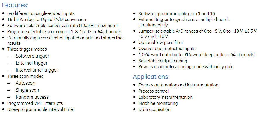
64 different or single ended inputs
16 bit analog-to-digital (A/D) conversion
Software selectable conversion rate (maximum 100kHz)
Programmable options for scanning channels 1, 8, 16, 32, or 64
Continuously digitize the selected input channel and store the results
Three triggering modes: software triggering, external triggering, and interval timer triggering
Three scanning modes: automatic scanning, single scan, and random access
Programmable VME interrupt
User programmable interval timer
Software programmable gains 1 and 10
External triggering can synchronize multiple boards simultaneously
Jumper selectable A/D range: 0 to+5V, 0 to+10V, ± 2.5V, ± 5V, and ± 10V
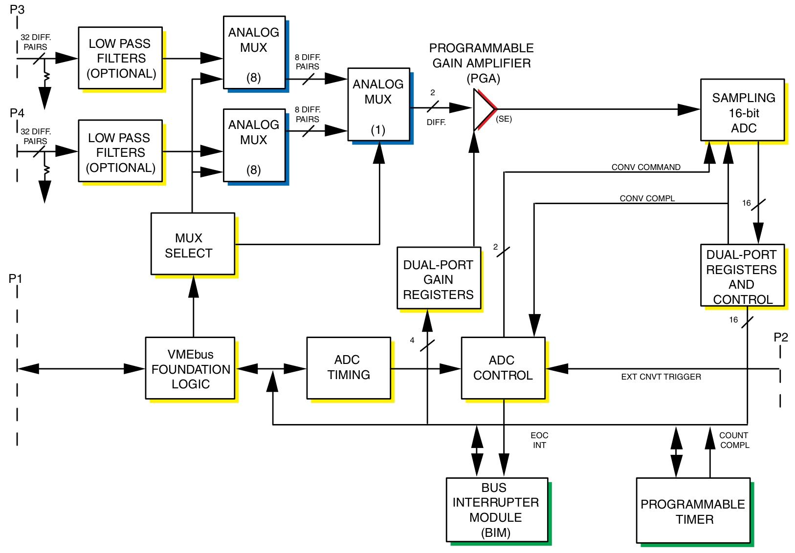
Optional low-pass filter
Over voltage protect
1024 word data buffer (16 word deep buffer x 64 channels)
Optional output encoding
When powered on, it is in automatic scanning mode with a gain of 1
Application Fields
Factory automation and instrumentation
process control
laboratory instruments
Machine monitoring
data acquisition
Ordering Options
Option Description
A (input filter option) 0=no filter; 1=10Hz(-3dB); 2=50Hz(-3dB); 3=100Hz(-3dB); 4=500Hz(-3dB)
B (channel quantity option) 0=64 channels high performance; 1=32 channels high performance; 2=16 channels high performance
C (input option) 0=differential analog input channel with 96 pin non latch connector; 1=Single ended analog input channel with 96 pin non latch connector; 2=Differential analog input channel with 64 pin latch connector; 3=Single ended analog input channel with 64 pin latch connector
DE 0 (reserved for future options)
F (Special Sales Order) 0=Standard VME front panel without conforming coating; 1=Reserved; 2=Standard VME front panel with conforming coating
Connector data
Recommended style for connecting components P3 and P4 I/O connectors
64 pin IDC mating connector (64 pin) Panduit 120-964-435
Strain relief (applicable to 64 pin connectors) Panduit 100-000-072
96 pin discrete mating connector (96 pin discrete) AMP 925486-1
Female crimping contact (96 pin discrete) AMP 530151-6
Connector housing (suitable for 96 pin connectors) Harting 09 03 096 0501
96 pin IDC mating connector (96 pin large-scale termination) ERNI 913.031
0.033-inch ribbon cable (96 pin large-scale termination) ERNI 913.049
Strain relief insert (0.033-inch ribbon cable) Harting 09 02 000 9912
Connector housing (suitable for 96 pin connectors) Harting 09 03 096 0501
PC board I/O connector part number Panduit 101-096-033A

Functional characteristics
1. Working mode
MODE
Software trigger: Start the selected scanning mode by writing the software trigger address
External trigger: The external trigger received on the P2 connector initiates the selected scanning mode
Interval timer trigger: Start the selected scanning mode each time the programmed time interval expires
SCAN
Automatic scanning: default scanning mode, all active channels are scanned continuously in order
Single scan: Start a single data burst (scanning all selected channels) from the selected trigger mode, stop and wait for another trigger after scanning all selected channels
Random access: Each time the selected trigger mode is enabled, a single channel can be selected, digitized, and stored
Channel automatic gain: The unique gain code for each channel is loaded from VME into the gain buffer, and the allocated code is retrieved in real-time from the buffer during each channel acquisition
Synchronization: A single scan or burst can be initiated by an external TTL trigger through the P2 connector (external trigger) or a local trigger through the control and status register (CSR) (software trigger), and any event will generate a P2 trigger output, which can be used to synchronize up to 15 cards
2. VME related characteristics
VME access: The response to the address modifier can be selected as A32, A24, or A16 address space through jumper wires; Monitoring or user privileges, or both
VMEbus compliance: Compliant with VMEbus specifications ANSI/IEEE STD 1014-1987, IEC 821 and 297, with 6U external dimensions
VME interrupt: An interrupt request can be generated at the end or in the middle of a buffer scan, or it can be initiated after collecting a specific number of samples (1 to 65535), and the response vector is controlled through the interrupt vector register
Data ready flag: When the data buffer is full (end of scan) or half full (middle of scan), the data ready flag in CSR is set
Interval timer: Programmable interval timer provides a time interval of up to 687 seconds
3. Reset operation
Board reset response system reset or writing software reset address
The reset operation automatically establishes the following default conditions: automatic scanning mode, 64 channel block size, 64 channel data buffer, channel gain=x1, 100kHz conversion rate
ADC will undergo a calibration cycle under any reset condition, which takes 41ms after the reset operation is initiated
4. Other functions
PGA: Channel gains of x1 and x10 can be selected through a programmable gain amplifier (PGA). The PGA gain can be configured through software as a single gain for all channels, or real-time control can be used to assign unique gains to each channel
Panel indicator: The front panel LED controlled by the program is powered on during the reset period and turned off through CSR
Board Identification: The Board Identification Register (BIR) contains the VME-3122A identification code
Input characteristics
Number of input channels: 64, 32, or 16 differential or single ended channels
Full range A/D range: ± 2.5V, ± 5V, ± 10V, 0 to+5V, 0 to+10V, jumper optional
Channel gain: Software configuration is x1 or x10
Full range input range
Gain=1: ± 2.5V to ± 10V (bipolar); 0 to+5V, 0 to+10V (unipolar)
Gain=10: ± 250mV to ± 1V (bipolar); 0 to+0.5V, 0 to 1V (unipolar)
Accuracy (% of FSR): There are different values for different ranges and gains, based on the average of 1000 samples
Stability: Temperature drift, per degree Celsius=± 25PPM (ADC reading) plus ± 5PPM (ADC range) plus ± 2.5 µ V
Input noise: (0.4+0.3/G) mV, where G=PGA gain (noise is independent of filter options)
Input bias current (typical/maximum): 50/120nA
Input impedance (minimum): Different DC differential, DC common mode, AC differential, and AC common mode impedances when the power is turned on and off
Channel crosstalk (DC to 1kHz): 80dB between adjacent channels within ± 10V range; 70dB between adjacent channels within ± 2.5V range
Common mode voltage range: (IVCM |+| VIN |. G) ≤ 10V, where VCM=common mode voltage, VIN=input voltage, G=gain
Common mode rejection: From DC to 60Hz, when the 350 Ω source is unbalanced, the minimum common mode rejection for gain 1 is 68dB, typical 80dB; the minimum common mode rejection for gain 10 is 76dB, typical 89dB; the minimum common mode rejection for+5V and ± 2.5V ranges is 66dB, which can be adjusted on-site to achieve the same common mode rejection as gain 1
Overvoltage protection: ± 35V (continuous) power on/off; ± 80V (transient, maximum 1s)
Input filter: Optional low-pass single pole filter with different -3dB values at different frequencies, frequency doubling in single ended (pseudo differential) applications, cut-off frequency tolerance of ± 25%, unfiltered input bandwidth (20Vp-p) typically 40kHz
Common mode/floating input protection: Both sides of each input are grounded through a 22M Ω resistor

Transmission characteristics
Resolution: 16 bits
Input sampling: order, starting from channel 00
Input transfer function:
E IN=E LO+E FSR × 65536N ADC, where E IN=input voltage, E LO=lower end of input range, E FSR=full-scale input range, N ADC=A/D converter reading
A/D conversion rate: 381 to 100kSPS
Channel sampling rate (maximum): 100kSPS (100kSPS ÷ number of channels in the scan block, minimum 1 channel)
Time interval: 305 µ s to 687s
Data encoding: programmable to choose binary complement or direct/offset binary
Data buffer storage
Buffer size: 16 to 1024 consecutive 16 bit data words, program controlled
Block size: 1, 8, 16, 32 or 64 channels, program controlled
Access time: maximum 600ns during non scanning; typical 600ns during scanning, maximum 1.2 µ s (maximum access time in scanning mode only occurs when VME access occurs within the ADC sampling window)
VME access: D8 to or D16
Availability: Can be accessed from VME at any time, buffer and block sizes are controlled through configuration control registers (CCR)
Physical/Environmental Specifications
Size: 6U (4HP) single slot Eurocard shape
Height: 9.2 inches (233.4mm)
Depth: 6.3 inches (160mm)
Thickness: 0.8 inches (20.3mm)
Power requirement: 3.0A at+5VDC (maximum)
Airflow: Forced air cooling is required
Temperature: Operating temperature 0 to+65 ° C; Storage temperature -40 to+85 ° C
Altitude: Working at 0-10000 feet (3000m); Storage 0-40000 feet (12000m)
Humidity: Working relative humidity 0% to 80%, no condensation
Input connectors (P3, P4): can be ordered as 96 pin DIN non latch or 64 pin DIN latch. The center row of the 96 pin non latch connector is grounded, while the center row of the 64 pin latch connector is not grounded. When using the 64 pin latch connector in differential mode, users can provide grounding on the front panel jumpers E1 and E2, which will result in channels 31 and 63 being configured as single ended
UIOC support
In UIOC, VME-3122A is used as a monitoring device. During initialization, UIOC programs VME-3122A to scan all 64 channels and sets the scanning mode to automatic scanning. Through UCLIO ™ Language, users can set programmable channel gains and command UIOC to retrieve data from any or all channels of VME-3122A. Through a menu driven calibration process, users can create and store channel gain and offset correction factors, which UIOC automatically uses to provide software gain and offset correction for each channel.
- OMRON
- ABB
- General Electric
- EMERSON
- Honeywell
- HIMA
- ALSTOM
- Rolls-Royce
- MOTOROLA
- Rockwell
- Siemens
- Woodward
- YOKOGAWA
- FOXBORO
- KOLLMORGEN
- MOOG
- KB
- YAMAHA
- BENDER
- TEKTRONIX
- Westinghouse
- AMAT
- AB
- XYCOM
- Yaskawa
- B&R
- Schneider
- KONGSBERG
- NI
- WATLOW
- ProSoft
- SEW
- ADVANCED
- Reliance
- TRICONEX
- METSO
- MAN
- Advantest
- STUDER
- DANAHER MOTION
- Bently
- Galil
- EATON
- MOLEX
- DEIF
- B&W
- ZYGO
- Aerotech
- DANFOSS
- Beijer
- Moxa
- Rexroth
- Johnson
- WAGO
- TOSHIBA
- BMCM
- SMC
- HITACHI
- HIRSCHMANN
- Application field
- XP POWER
- CTI
- TRICON
- STOBER
- Thinklogical
- Horner Automation
- Meggitt
- Fanuc
- Baldor
- SHINKAWA
- Other Brands
- UniOP
- KUKA
- Iba
- Beckhoff
- ADLINK
-
 Applied Materials 0195-14157 CMP Tool Controller
 -
 Allen-Bradley SK-H1-PWRMOD-D590 Power Structure
 -
 Zebra RSR12-RG5G8G5G5A1A2B XSLATE R12 Rugged Tablet
 -
 LTI SC52.0040.0012.0000.0 Compact Servo Drive
 -
LTI Tools LT4400-30 Twist Socket 1/2 inch Drive
-
 Lust LTi CDE32.008 Position Controller
 -
 LUST B-DS 125.1 LTi Drives 181-00635 Module
 -
 LTI DRIVES MS100 Montageset 0927.0017
 -
 Lust LTi Servo One SO84.032.0043.0000.2 Drive
 -
 LTI CDF 30.008.C3.6 Drive Power Supply
 -
 LTI SC52.0040.0012.0000.0 Servo Drive
 -
 LTi Drive CDF30.002 Power Supply Fuse
 -
 LTI Tools LT-4621-D Deep Well Twist Socket
 -
 MOOG LTI CDE54.044.D Pitch Master Turbine Drive
 -
 LTI TOOLS LT-1460 Wheel Torque Extension Kit
 -
 LUST LTi SO82.004.0030.0000.2 Servo Drive
 -
 LTI MOTION SA54.0075.0033.0000.0 Servo Drive
 -
 LUST LTi CDE34.006 W2.0 BR Servo Drive
 -
LUST LTi MOTION CDE34.044 W2.4 H13 Servo Drive
-
LUST LTi CDE32.008 W2.2.BR Positioning Controller
-
 LUST LTi DRiVES B-DS 125.1 Braking Resistor
 -
 LTI MOTION CDE34.006.WXX.PC1 Servo Drive
 -
 LTI MOTION SO24.007.0030.1000.0 Servo Drive
 -
Lust CDD34.005.C2.1 LTI Drive
-
LTI SC52.0040.0012.0000.0 Compact Servo Drive
-
LTI Tools LT4400-30 Twist Socket 1/2 inch Drive
-
 Lust LTi CDE32.008 Position Controller
 -
 LUST B-DS 125.1 LTi Drives 181-00635 Module
 -
LTI DRIVES MS100 Montageset 0927.0017
-
 Lust LTi Servo One SO84.032.0043.0000.2 Drive
 -
LTI CDF 30.008.C3.6 Drive Power Supply
-
LTI SC52.0040.0012.0000.0 Servo Drive
-
LTi Drive CDF30.002 Power Supply Fuse
-
LTI Tools LT-4621-D Deep Well Twist Socket
-
 LTI Tools LT-1400C Wheel Torque Extension
 -
LTI SO CM-P.0122.2015.1 Servo Drive SA000-13029N
-
LTI MOTION SC32.0075.1011.0000.0 Servo Drive
-
 LTI MOTION SC34.0200.0011.0000.0-SL Servo Drive
 -
 LTI CDE34.017 W2.4 H18 Frequency Inverter
 -
 LTI SO CM-P.0122.2015.1 Servo Drive
 -
 LTI FLPF-142-3-12-560/T4 Servomotor
 -
 MOOG LTI CDE54.044.D Pitchmaster Turbine Drive
 -
Lust LTi CDB34.003.C2.4 SH Servo Controller
-
 LTI SC52.0040.0012.0000.0 Servo Drive
 -
LTI SA52.0100.0033.0000.0 Servo Driver
-
 LUST CDE 54.044.D Pitch Master Turbine Drive
 -
 Lust LTi Servo One SO84.032.0040.0000.2 Drive
 -
 LTi LSH-074-2-60-560/T1 P S4 B14.1R Servo Motor
 -
LTI SC52.0040.0012.0000.0 Servo Drive
-
 LTI CDS44.072.LC1.1.NF Servo Driver
 -
 LTI SO CM-P.0122.2015.1 Servo Drive
 -
LTI MOTION SO24.007.0030.1000.0 Servo Drive
-
LTI MOTION SC34.0300.0011.0000.0 Servo Drive
-
 LTI DRIVES GmbH MS100 Mounting Set 0927.0017
 -
 LTI CDB34.014 W2.4 BR SH Servo Driver
 -
LTi Drives 0920.0034.14 Documentation DVD
-
 LTI MOOG CDE54.044 Pitchmaster Frequency Converter 181-01019
 -
LTI LSN-097-0960-30-560 Servo Motor
-
LUST LTI CDE32.008 W2.2.BR Positioning Controller
-
LTI Drives MS100 0927.0017 Assembly Set
-
 LTI SO82.004.0030.0000.2 Servo Drive
 -
LTI MOTION SC32.0040.1011.0000.0 Servo Drive
-
LTi Drives 0920.0034.14 Product DVD
-
LTI MOOG CDE54.044 Pitchmaster Servo Drive 181-01019
-
LUST LTI CDE34.017 W2.4 Servo Drive
-
 Lust LTi Servo One SO84.032.0040.0000.2 Drive
 -
 LUST LTI SO84.012.0011.1700.2 Servo Drive
 -
LTI LSN-097-0960-30-560 Servo Motor
-
LUST CDE 54.044.D Pitch Master Turbine Drive
-
 LTI Luster SA54.0550.0033.0000.0 Servo Drive
 -
LTI CDS44.072.LC1.1.NF Servo Driver
-
 LTI DRIVES GmbH MS100 Assembly Set 0927.0017
 -
 LTi Drives DSM4-14.2-21R83-200 Servo Motor
 -
LTI Motion SC52.0150.0012.0000.0 Servo Drive
-
LTI Motion LSP04-004-048-60-0PR1PY17E0440 Servo Motor
-
 LTI KP300-R Drive Interface Operator Display
 -
 Lust LTI SO84.020.0002.0100.2 Servo Drive
 -
 LUST LTI CDD34.008.W2.1 CDD3000 Servo Drive
 -
LTI MOTION SA54.0550.0033.0000.0 Servo Drive
-
 LTI Drives MS100 0927.0017 Mounting Kit
 -
 LTi DRiVES LSP06-015-320-30-00H1MY170 Servo Motor
 -
 LTI MC6412 C1 D3 S12 Servo Drive
 -
LUST LTi SO82.004.0030.0000.2 Servo Drive
-
LTi Drives LSP06-015-320-30-00H1MY170 Servomotor
-
LUST LTi CDE34.003 C2.0 Servo Drive
-
LUST LTi LSH-127-1-30-560 T1 Servo Motor
-
 LTI MOOG CDE54.044 Pitchmaster Servo Drive
 -
LTI Lock Technology 1237 Flip Socket Set
-
LTi LSP08-028-560-55-00H1MY1M0 Servomotor
-
Lust LTi CDE34.010.D2.4 Position Controller 10A
-
 Lust LTi CDE34.010.D2.4 Positioning Controller 10A
 -
LTi Drives FLPF-142-3-12-560/T4 Servomotor
-
 LUST LTI Motion CDD54.045 W2.1 Servo Drive
 -
LUST LTI CDD34.006.W2.2.PC1 Servo Drive
-
 LTI KP200-XL Operator Panel Keypad 4 Key
 -
 Lust LTI CDE32.008 W2.2.BR Positioning Controller
 -
LTI Servo One SO82.004.0030.0000.2 Drive Amplifier
-
LTI MOTION SC54.0550.0012.0000.0 Servo Drive
-
LTI LSN-097-0510-30-560 Servo Motor
-
LTi Drives 0920.0034.14 Product DVD
-
LTI SO82.004.0030.0000.2 Servo Drive
-
MOOG LTI CDE54.044 Pitchmaster Frequency Converter
-
LUST LTI CDE34.017 W3.0 Servo Drive
-
LUST LTi Drives CDS44.072 LC1.1 Servo Drive
-
LUST LTi DC1-3.0006.1000.0 Servo Drive
-
LTi LSMM13-100-4N-001 Servo Motor
-
LTI MOOG CDE54.044 Pitchmaster Servo Drive
-
 LUST LTi Drives NFE12.3 Line Filter
 -
LTI MOTION SC34.0100.1011.0000.0 Drive
-
LUST LTi LSH-074-2-30-560/T1 B S4 G6.1M Servomotor
-
LUST LTI CDE34.044W2.3 Servo Drive
-
LUST LTi LST-127-5-15-560/T1 S4 G12.1S Servomotor
-
Lust LTi MOTION CDE34.044 W2.4 H13 Servo Drive
-
LTI Servo One SO82.004.0030.0000.2 Drive Amplifier
-
Lust LTI CDE34.006 W2.4 V4.10-02 Servo Controller
-
LTI Drives Stromag FLP 20/0014-60 BA 1 Servomotor
-
Lust LTI CDE34.024.Wx.x.PC1 Servo Controller
-
LTI Drives FLP13-0395-30-AC2 9.5 kW Servo Motor
-
LTI CDB32.004-C2.0SH Servo Drive
-
LTi LSH-074-2-30-320/T1 1R Servo Motor
-
LTi DRiVES LSP08-028-320-30-BPH2MY17E0803 Servo Motor
-
LUST LTI SO24.007.0020.0000.1 Servo Controller
-
LTI CDE34.017.W3.0 Frequency Inverter
-
LUST LTi DRIVES LSH-097-0960-30-560/T1 Servomotor
-
LTi DRiVES LSP10-056-560-50-00H1MY 1M0 Servomotor
-
LTi DRiVES LSP08-028-320-55-00H1MY 170 Servomotor
-
 LTI MC6432 C1 D3 S12 G20 Servo Drive
 -
 Keba LTi CDE32.008 C3.0 Frequency Inverter


