
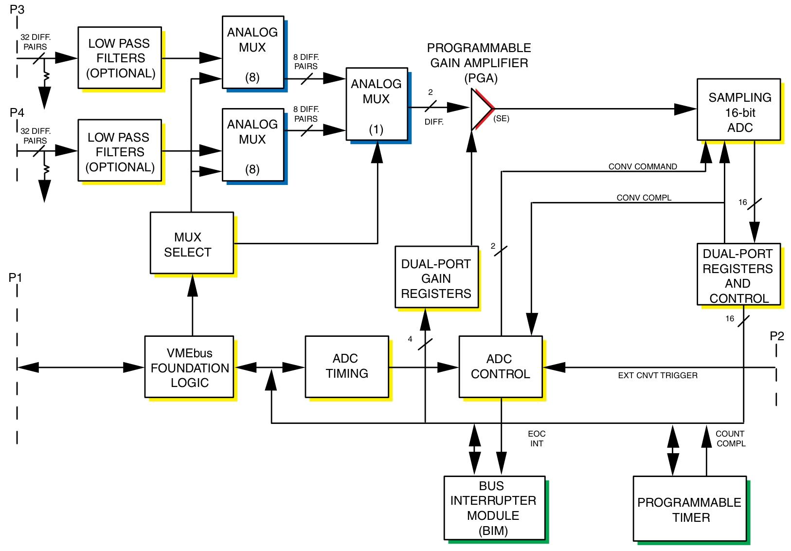
GE VME-3122A High Performance 16 Bit Analog to Digital Converter (ADC)
Panel indicator: The front panel LED controlled by the program is powered on during the reset period and turned off through CSR
Board Identification: The Board Identification Register (BIR) contains the VME-3122A identification code
Input characteristics
Number of input channels: 64, 32, or 16 differential or single ended channels
Full range A/D range: ± 2.5V, ± 5V, ± 10V, 0 to+5V, 0 to+10V, jumper optional
Channel gain: Software configuration is x1 or x10
Full range input range
Gain=1: ± 2.5V to ± 10V (bipolar); 0 to+5V, 0 to+10V (unipolar)
Gain=10: ± 250mV to ± 1V (bipolar); 0 to+0.5V, 0 to 1V (unipolar)
Accuracy (% of FSR): There are different values for different ranges and gains, based on the average of 1000 samples
Stability: Temperature drift, per degree Celsius=± 25PPM (ADC reading) plus ± 5PPM (ADC range) plus ± 2.5 µ V
Input noise: (0.4+0.3/G) mV, where G=PGA gain (noise is independent of filter options)
Input bias current (typical/maximum): 50/120nA
Input impedance (minimum): Different DC differential, DC common mode, AC differential, and AC common mode impedances when the power is turned on and off
Channel crosstalk (DC to 1kHz): 80dB between adjacent channels within ± 10V range; 70dB between adjacent channels within ± 2.5V range
Common mode voltage range: (IVCM |+| VIN |. G) ≤ 10V, where VCM=common mode voltage, VIN=input voltage, G=gain
Common mode rejection: From DC to 60Hz, when the 350 Ω source is unbalanced, the minimum common mode rejection for gain 1 is 68dB, typical 80dB; the minimum common mode rejection for gain 10 is 76dB, typical 89dB; the minimum common mode rejection for+5V and ± 2.5V ranges is 66dB, which can be adjusted on-site to achieve the same common mode rejection as gain 1
Overvoltage protection: ± 35V (continuous) power on/off; ± 80V (transient, maximum 1s)
Input filter: Optional low-pass single pole filter with different -3dB values at different frequencies, frequency doubling in single ended (pseudo differential) applications, cut-off frequency tolerance of ± 25%, unfiltered input bandwidth (20Vp-p) typically 40kHz
Common mode/floating input protection: Both sides of each input are grounded through a 22M Ω resistor

Transmission characteristics
Resolution: 16 bits
Input sampling: order, starting from channel 00
Input transfer function:
E IN=E LO+E FSR × 65536N ADC, where E IN=input voltage, E LO=lower end of input range, E FSR=full-scale input range, N ADC=A/D converter reading
A/D conversion rate: 381 to 100kSPS
Channel sampling rate (maximum): 100kSPS (100kSPS ÷ number of channels in the scan block, minimum 1 channel)
Time interval: 305 µ s to 687s
Data encoding: programmable to choose binary complement or direct/offset binary
Data buffer storage
Buffer size: 16 to 1024 consecutive 16 bit data words, program controlled
Block size: 1, 8, 16, 32 or 64 channels, program controlled
Access time: maximum 600ns during non scanning; typical 600ns during scanning, maximum 1.2 µ s (maximum access time in scanning mode only occurs when VME access occurs within the ADC sampling window)
VME access: D8 to or D16
Availability: Can be accessed from VME at any time, buffer and block sizes are controlled through configuration control registers (CCR)
Physical/Environmental Specifications
Size: 6U (4HP) single slot Eurocard shape
Height: 9.2 inches (233.4mm)
Depth: 6.3 inches (160mm)
Thickness: 0.8 inches (20.3mm)
Power requirement: 3.0A at+5VDC (maximum)
Airflow: Forced air cooling is required
Temperature: Operating temperature 0 to+65 ° C; Storage temperature -40 to+85 ° C
Altitude: Working at 0-10000 feet (3000m); Storage 0-40000 feet (12000m)
Humidity: Working relative humidity 0% to 80%, no condensation
Input connectors (P3, P4): can be ordered as 96 pin DIN non latch or 64 pin DIN latch. The center row of the 96 pin non latch connector is grounded, while the center row of the 64 pin latch connector is not grounded. When using the 64 pin latch connector in differential mode, users can provide grounding on the front panel jumpers E1 and E2, which will result in channels 31 and 63 being configured as single ended
UIOC support
In UIOC, VME-3122A is used as a monitoring device. During initialization, UIOC programs VME-3122A to scan all 64 channels and sets the scanning mode to automatic scanning. Through UCLIO ™ Language, users can set programmable channel gains and command UIOC to retrieve data from any or all channels of VME-3122A. Through a menu driven calibration process, users can create and store channel gain and offset correction factors, which UIOC automatically uses to provide software gain and offset correction for each channel.
- OMRON
- ABB
- General Electric
- EMERSON
- Honeywell
- HIMA
- ALSTOM
- Rolls-Royce
- MOTOROLA
- Rockwell
- Siemens
- Woodward
- YOKOGAWA
- FOXBORO
- KOLLMORGEN
- MOOG
- KB
- YAMAHA
- BENDER
- TEKTRONIX
- Westinghouse
- AMAT
- AB
- XYCOM
- Yaskawa
- B&R
- Schneider
- KONGSBERG
- NI
- WATLOW
- ProSoft
- SEW
- ADVANCED
- Reliance
- TRICONEX
- METSO
- MAN
- Advantest
- STUDER
- DANAHER MOTION
- Bently
- Galil
- EATON
- MOLEX
- DEIF
- B&W
- ZYGO
- Aerotech
- DANFOSS
- Beijer
- Moxa
- Rexroth
- Johnson
- WAGO
- TOSHIBA
- BMCM
- SMC
- HITACHI
- HIRSCHMANN
- Application field
- XP POWER
- CTI
- TRICON
- STOBER
- Thinklogical
- Horner Automation
- Meggitt
- Fanuc
- Baldor
- SHINKAWA
- Other Brands
- UniOP
- KUKA
- Iba
- Beckhoff
- ADLINK
-
 Basler Electric 9289902106 Circuit Board
 -
 Basler Electric BE1-32R Protective Relay A1E E1P BOS1P
 -
 Basler Electric RAL6144-16GM GigE Line Scan Camera with Lens
 -
 Basler Electric BE3-49R-5I5A1 Temperature Relay
 -
 Basler Electric BE1-32R Power Relay B3E E1R A0N1F
 -
 Basler Electric SR4A2B06B3A Static Voltage Regulator Features
 -
 Basler Electric 9121000106 Manual Voltage Control MVC Guide
 -
 Basler Electric SR32A-2B15B3E Static Voltage Regulator
 -
 Basler Electric SR4A2B06B3A Static Voltage Regulator Guide
 -
 Basler Electric 801A193F02 Hammond Transformer Module
 -
 Basler Electric BE1-24 Volts Per Hertz Relay A1E F1J D1S0F
 -
 Basler Electric AEC63-7 Analog Excitation Controller 220-277V
 -
Basler Electric BE132R Power Relay T245579
-
 Basler Electric MVC 108 Manual Voltage Control 90 37000 102
 -
 Basler Electric 9022900-103 Control Transformer 6-7VA 60Hz
 -
 Basler Electric BE1-79M Plug Adapter 9170111102
 -
 Basler Electric 9 2007 00 100 Current Boost System CBS 305
 -
 Basler Electric SR4A2B01B3A Static Voltage Regulator 120V
 -
Basler Electric BE1-32R Power Solid State Relay E2E A10 A0N0F
-
 Basler Electric PRS250 Veri-Sync Relay 9088800102
 -
 Basler DECS 125-15-B2C Digital Excitation Control
 -
 Basler BE 13693 002 Transformer
 -
Basler BE1-59N Ground Fault Overvoltage Relay
-
 Basler BE1-79A Reclosing Relay
 -
 Basler 9-1051-00-105 Overload Protection Module
 -
 Basler BE1-32R Power Relay – Directional Overcurrent Guide
 -
 Basler 9319700103 BE3-27T/59T-3A1N3 Voltage Relay
 -
 Basler BE1-87G Generator Differential Relay
 -
 Basler BE3-25-1D1N4 9319100106 480V Relay
 -
 Basler SR8A2B07B3A Static Voltage Regulator
 -
 Basler Electric BE4-27/59 Over/Under Voltage Relay 307-2552
 -
Basler Electric SR32A2B05B3E Static Voltage Regulator
-
Basler Electric BE1-27 A3E C3J A1N6F Solid State Protective Relay
-
 Basler Electric 9174700-100 Excitation Limiter Generator
 -
 Basler Electric BE1-87G Generator Differential Relay 09833
 -
 Basler Electric 9310200100 Power Supply Module
 -
 Basler Electric TIEE1CD0N07 Control Module
 -
Basler Electric BE1-59N Ground Fault Relay T214750
-
Basler Electric SR8A2B10B3AX Static Voltage Regulator 9060200126
-
 Basler Electric SSR 125-12 Voltage Regulator
 -
 Rolls Royce H1111.0204 Ship Main Controller
 -
 Basler Electric BE3-32-3AC Reverse Power Relay 9 1376 00 105
 -
Basler Electric BE3-25-1A1N4 Synch Check Relay 9319100100
-
 Basler Electric SR4A-2B15B3A Static Voltage Regulator
 -
 Basler Electric SR4A-2B15B3E Static Voltage Regulator
 -
 Basler Electric 9170818100 Solid State Protective Relay
 -
 Basler Electric AEC63-7 Analog Excitation Controller
 -
 Basler Electric 17483 Auxiliary Module
 -
Basler Electric BE1-59 Over Voltage Relay
-
Basler Electric 21600-101 Control Module
-
 Basler Electric KR2F Generator Voltage Regulator 9056600100
 -
 Basler BE1-CDS Current Differential System
 -
 Basler Electric CBS 212 Current Boost System 9 2650 00 100
 -
 Basler Electric IFM-150 Firing Circuit Chassis
 -
 Basler Electric BE1-60 Voltage Balance Relay C1F A1P D0C3F
 -
Basler Electric BE1-32R Power Relay A2E D1R A0N0F
-
Basler Electric BE1-32R Power Relay A2E D1R A0N0F
-
 Basler Electric 8650C80G01 Isolation Transducer PCB Board
 -
 ETEL EA-P2M-300-4/7.5A-0100-01 AccurET Modular 300 Servo Drive
 -
 Basler Electric 87T Transformer Differential Relay
 -
Basler Electric BE-6868 Power Transformer 5950007559202
-
 Basler Electric PRS250 Veri-Sync Relay 9088800102
 -
 Basler Electric SCP-250-G-60 VAR Power Factor Controller
 -
 Basler DECS-150 AVR 1NS2V1N1S Voltage Regulator
 -
Basler UFOV 260A Under Frequency Overvoltage Module
-
 Basler MOC2 199 Motor Operated Control – Overview and Setup
 -
 Basler BE3-49R-5K5A1 Temperature Relay – Complete Guide
 -
Basler BE 20035 001 Transformer – Technical Data and Installation
-
 Basler BE 02727 001 Transformer – Specifications and Usage
 -
 Basler BE127 Under Voltage Relay – Features and Application Guide
 -
Basler CBS377 Current Boost System – Complete Technical Guide
-
Basler BE1-87G P/N 9170818100 Differential Relay – In-Depth Specs
-
Basler BE1-87G Generator Differential Relay – Technical Overview
-
Basler Electric SR4A2B16 SVR Static Voltage Regulator – Complete Guide
-
 Basler Electric 9261500101 Power Supply Module
 -
 Basler Electric AEM-2020 Analog Expansion Module
 -
Basler Electric DGC-2020 Digital Genset Controller 51BRBNEAH001
-
Basler Electric BE1-59N Ground Fault Overvoltage Relay
-
Basler Electric BE1-59N-A5E-E1L-N0S1F Neutral Overvoltage Relay
-
Basler Electric MOC2499 Motor Operator Control Potentiometer 9072300430
-
 Basler Electric BE1-50/51M Overcurrent Relay
 -
 Basler Electric 9148100106 MOC3502 Solid State Relay 250VDC 0.25A
 -
 Basler Electric CBS 212 Current Boost System 9265000100
 -
Basler Electric 10493002 Control Module
-
Basler BE1-32R D3E E1R A0N1F Power Relay
-
 Basler SR8A2B15B3A Static Voltage Regulator
 -
 Basler IFM-105 Firing Circuit Chassis 9324100105
 -
Basler SR4A2B05B3A Static Voltage Regulator
-
 Basler BE151G1EB6PB0N0F Protective Relay
 -
Basler BE1-59 Electric Over Voltage Relay
-
 Basler 277 Static Programmable Powerline Carrier Channel
 -
Basler BE1-32R D1E A1P A0N1F Power Relay
-
Basler SR4A1B07B3A Static Voltage Regulator
-
 Basler Electric BE1-700 Digital Protective Relay
 -
Basler Electric SR8A-2B01B3A Static Voltage Regulator
-
Basler Electric SR4A-2B01B3E Static Voltage Regulator
-
Basler Electric 9017709102 PC Board
-
Basler Electric SR4A-2B01B3A Static Voltage Regulator
-
Basler Electric PRS-250 Veri-Sync Relay
-
 Basler Electric 9066800102 Excitation Support System
 -
Basler Electric BE1-87G Generator Differential Relay 9 1708 18 100
-
 Basler Electric 36T865-2 BE03752001 Power Supply
 -
 Basler Electric M-300 149D940G02 Power Supply
 -
 Basler Electric ACA2040-25GM 4Mp 25Fps Area Scan Camera
 -
 Basler BE1-87G-S1A-A1C-A0N0 Differential Relay
 -
Basler SR8A-2B06B3E Static Regulator SR8A2B06B3E
-
 Basler SCP-210 Frequency Controller 9095400100
 -
 Basler BE1-59-A3E-A1J-N1N3F Overvoltage Relay BE159A3EA1JN1N3F
 -
Basler 9 2011 11 100 Bracket Mounted Terminal Unit
-
Basler 9 1606 00 101 Voltage Regulator
-
 Basler CBS-377 Current Boost System 9109600102
 -
Basler 8650C72 Exciter Control Module PCB Rev 5
-
Basler C2EE1PA0N1F BE1-32R Reverse Power Relay
-
 ADLINK HPCI-14S12U - Industrial Control Backplane 12PCI Backplane PCI-14S Passive Backplane
 -
-0010.png) ADLINK PCIe-GIE74C - image acquisition card 4-CH GigE Vision PoE+ Frame Grabber
ADLINK PCIe-GIE74C - image acquisition card 4-CH GigE Vision PoE+ Frame Grabber -
-0010_1.png) ADLINK PCI-8164 - control card 4-Axis Advanced Motion Controller Board
ADLINK PCI-8164 - control card 4-Axis Advanced Motion Controller Board -
 ADLINK PCIe-U304 - 4 Port USB3 PCIe Frame Grabbers USB Screw Hole Card
 -
 ADLINK PCI-9112 - Multi-Function Data Acquisition Card DAQ Card
 -
 ADLINK PCI-7432 - 51-12013-0A50 4-CH Isolated Numérique I/O PCI Cartes Digital I/O Card
 -
 ADLINK PCA-6106P3-0C1 REV.C1 - backplane 6-Slot Passive Backplane Board
 -
 ADLINK PCI-7224 - 24-CH Opto-Isolated Digital I/O PCI Board
 -
 ADLINK CPCI-7433R(G) - Digital Input Board Rear I/O CompactPCI Card
 -
 ADLINK EBP-13E4 - 51-46703-0A30 Industrial PC Backplane Passive Backplane
 -
 ADLINK PCIE-HDV62 - Image acquisition card High Definition Video Frame Grabber
 -
 ADLINK EBP-13E4 - 51-46703-0A30 Industrial Backplane Board Passive Backplane
 -
 ADLINK 90111-B1 / CPCI-6770 - PCB CPU MODULE CompactPCI Single Board Computer
 -
 ADLINK PCI-7248 - DATA ACQUISITION PCI CARD 48-CH Parallel Digital I/O Board
 -
 ADLINK PCI-7230 - 51-12003-0a50 board PCI7230 32-CH Isolated Digital I/O Card


