
Westinghouse WGen2000, WGen3600, and WGen3600V portable generators
Westinghouse WGen2000, WGen3600, and WGen3600V portable generators
Core parameters and configuration of the product
1. Basic parameters (common/difference comparison among three models)
Parameter category WGen2000 WGen3600 WGen3600V
Operating power 2000 Watts 3600 Watts 3600 Watts
Peak power 2500 Watts 4650 Watts 4650 Watts
Fuel tank capacity 15L/4.0 gallons 15L/4.0 gallons 15L/4.0 gallons
Rated speed 3600 RPM 3600 RPM 3600 RPM
Ignition type TCI (transistor ignition) TCI (transistor ignition) TCI (transistor ignition)
Spark plug model F7TC F7TC F7TC
Engine displacement 212 cc 212 cc 212 cc
Cylinder diameter x stroke 55 x 70 55 x 70 55 x 70 55 x 70
Oil capacity 0.60 L 0.60 L 0.60 L
Recommended engine oil 10W30 (4-stroke engine oil) 10W30 (4-stroke engine oil) 10W30 (4-stroke engine oil)
Total Harmonic Distortion (THD) < 23% < 23% < 23% < 23%
Special configuration - non inflatable wheels, integrated rubber handle-
California compliance configuration optional CARB carbon canister optional CARB carbon canister standard CARB carbon canister
2. Core components and functions
Control panel: including main circuit breaker, multiple power sockets (120V 20A dual socket, 120V 30A trailer specific socket, 120V 30A twist lock socket), grounding terminals, WGen2000 dual socket maximum load of 18A, other models are 20A.
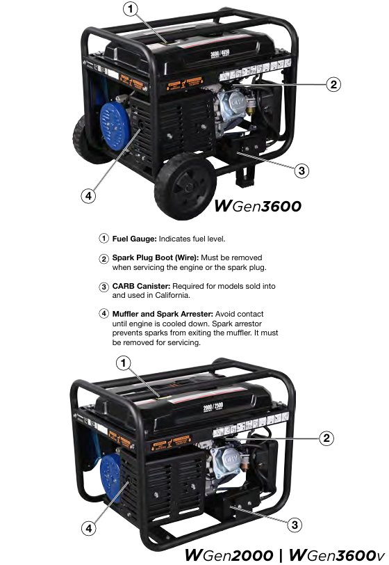
Engine components: including fuel tank (with oil level gauge), muffler and spark arrester (fireproof flower leakage), ignition coil assembly, throttle return spring, governor linkage device, etc.
Safety components: low oil level automatic shutdown switch (cutting off the engine when there is insufficient oil), circuit breaker (overload protection), GFCI socket (some models, anti leakage).
Safety operation standards (top priority)
1. Environmental safety requirements
Only operate in outdoor ventilated areas, away from doors, windows, ventilation openings, and flammable materials. The minimum safe distance is 6 feet (1.8 meters). It is strictly prohibited to use indoors, in garages, or in enclosed spaces (engine exhaust contains carbon monoxide, colorless, odorless, and highly toxic).
It should be placed on a flat and hard surface, avoiding loose environments such as sand and grass (to prevent debris from blocking the air intake or cooling system); Do not use in rainy, snowy, humid environments or areas with accumulated water (to prevent short circuit and electric shock).
Avoid high temperature and high conductivity areas (such as metal decks, steel construction sites), and operate without open flames or sparks (such as cigarettes, matches, static power sources) around.
2. Fuel safety operation
Only use unleaded gasoline grade 87 and above, with an ethanol content not exceeding 10%. It is strictly prohibited to use 2-stroke engine oil, diesel, or other fuels.
Before refueling, the machine must be stopped and cooled to a surface that is not hot to the touch. Clean the surrounding area before opening the fuel tank cap and slowly refuel, not exceeding the neck of the refueling port (leaving space for fuel expansion).
If there is a fuel leak, immediately wipe it clean with a cloth and dispose of the cloth properly. Wait for the leaking area to dry before starting the generator; Wear goggles when refueling to avoid prolonged skin contact with fuel or inhalation of vapor.
Fuel containers should be stored in a well ventilated area, away from sources of ignition, and the use of gasoline as a cleaning agent is strictly prohibited.
3. Electrical safety operation
Before starting, it must be properly grounded: if used as a backup power source to connect to household circuits, a certified electrician must install a transfer switch and set up a grounding rod (in accordance with the national electrical code NEC and local regulations); Use grounding extension cords and three core/double insulated electrical appliances.
Do not touch the live terminals or exposed wires of the running generator, and do not operate with wet hands or when the generator is damp; Do not use damaged or aged power cords, and the plug should be fully inserted into the socket (the 240V socket should be fixed by rotating 1/4 turn clockwise).
Do not use generators to supply power to medical support equipment to avoid loads exceeding the rated power of sockets or circuit breakers.
4. Safety check before operation
Confirm that all loads have been disconnected (unplug external appliances and extension cords).
Check the engine oil level (new engines need to be filled with oil first, starting without oil will damage the engine).
Check the fuel quantity, whether the fuel pipeline leaks, and whether the air filter is clean.
Remove tools, cloths, and other debris placed during maintenance to ensure there are no obstacles around.
Complete operation process (start run stop)
1. Preparation before startup
Site selection: Outdoor ventilation, flat and hard, dry, away from combustibles and ventilation openings.
Grounding: Connect the grounding terminal as required (operated by an electrician when a grounding rod is required).
Oil inspection:
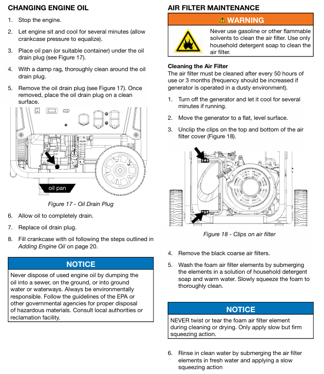
Engine oil: After cooling down the machine for a few minutes, clean the area around the oil filling port, take out the dipstick and wipe it clean, completely unscrew it, and then take it out again. The oil level should be between the H (high) and L (low) marks. If it is insufficient, add 10W30 4-stroke engine oil (to avoid excess).
Fuel: Ensure that the fuel tank has sufficient qualified gasoline and check if the fuel valve is closed (before starting).
Load disconnection: Disconnect all external electrical appliances and extension cords, and confirm that the circuit breaker is in the reset state.
2. Manual startup steps (applicable to all three models)
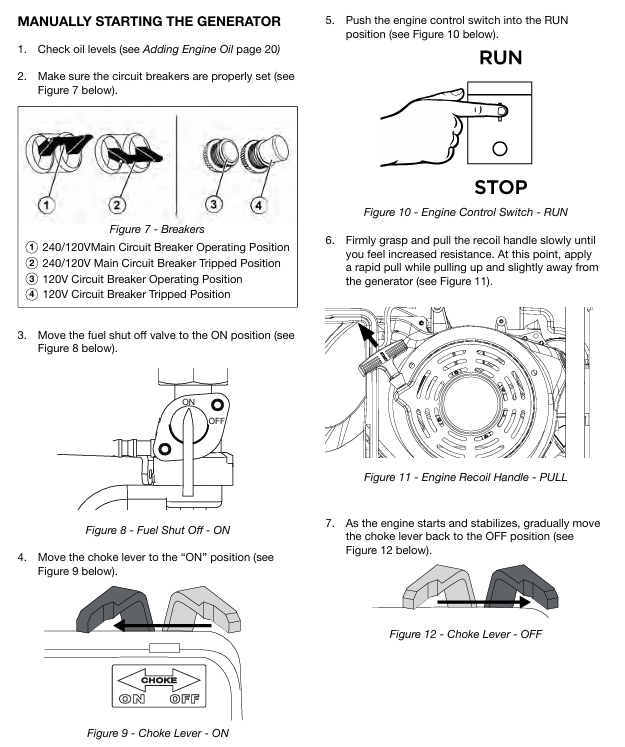
Reset circuit breaker: Set the main circuit breaker and branch circuit breaker to the "ON" position (reset if tripped previously).
Open the fuel valve: Switch the fuel shut-off valve to "ON" (ensure that fuel flows to the engine).
Adjust the air door: Turn the air door handle to the "ON" position (necessary for cold engine start-up, can be omitted for hot engine).
Start switch: Push the engine control switch to the "RUN" position.
Pull the recoil starter: Slowly pull the recoil handle until you feel an increase in resistance (compression stroke), then quickly pull upwards and slightly away from the generator direction, repeating until the engine starts.
Stable engine: After starting the engine, wait for the speed to stabilize and gradually turn the throttle handle back to the "OFF" position (to avoid unstable operation caused by excessive mixture).
Connect the load: After confirming that the generator is running smoothly, connect the electrical appliances one by one (the total load does not exceed the rated power).
3. Precautions during operation
Real time observation of operating status: If there is abnormal noise, excessive vibration, smoking, sparks, or overheating of the socket, immediately stop the machine for inspection.
Avoid overload: It is forbidden to connect multiple high-power electrical appliances at the same time. If the circuit breaker trips, disconnect the load first, cool down, and then reset to investigate the cause of overload.
Fuel replenishment: When there is insufficient fuel during operation, it is necessary to first shut down for cooling, and then refuel according to the requirements of fuel safety operation.
Altitude adaptation: For every 300 meters (1000 feet) increase in altitude, the engine power decreases by about 3.5%, and the power decrease is even more significant when the carburetor is not modified. High altitude use requires early modification of the carburetor.
4. Shutdown steps
Normal shutdown
Disconnect the load: First unplug all external appliances and extension cords.
No load cooling: Run the generator without load for 3-5 minutes to reduce the temperature of the engine and generator.
Turn off the engine: Set the engine control switch to the "STOP" position; If stored for a long time, first close the fuel valve and let the engine run until the fuel runs out before automatically stopping (clearing the carburetor to prevent fuel deterioration).
Emergency shutdown
When encountering risks of fire, leakage, electric shock, or engine abnormalities, simply turn the engine control switch to the "STOP" position without the need for idle cooling.
Maintenance and upkeep (extend lifespan+ensure safety)
1. Maintain safety prerequisites
Stop the machine and cool it down until the surface is not hot to the touch, then remove the spark plug cap (to prevent accidental start-up); The electric starter model requires disconnecting the negative cable of the battery.
Maintain good ventilation in the area, keep away from sources of fire, avoid skin contact with engine oil and fuel, and wear gloves and goggles.
Do not use gasoline or flammable solvents to clean components. Waste engine oil and cleaning fluids must be disposed of properly in accordance with EPA or local regulations and cannot be dumped.
2. Long term storage and maintenance (not used for more than 30 days)
Cleaning the body: Clean dust, debris, and oil stains according to daily cleaning requirements.
Handling fuel:
Method 1: Drain the fuel tank, open the fuel valve, start the engine until the fuel runs out, and automatically stop (empty the carburetor).
Method 2: Add fuel stabilizer, fill the fuel tank (reduce air contact), run for 10 minutes to circulate stabilizer to the carburetor, and close the fuel valve.
Change engine oil: Follow the oil change steps to replace the new engine oil to avoid the old oil from deteriorating and corroding the engine.
Protect the cylinder: Remove the spark plug, inject 1 tablespoon of clean engine oil, pull the recoil handle several times by hand (to evenly apply the oil to the cylinder wall), and reinstall the spark plug.
Storage environment: dry, ventilated, cool, away from sources of fire and corrosive substances. WGen3600 needs to remove the wheels or cushion the body to avoid tire deformation under pressure.
Regular inspection: Pull the recoil handle several times a month (without starting) to keep the components moving.
Common troubleshooting (problem cause solution)
1. Engine running but no power output
Potential cause solutions
The main circuit breaker or branch circuit breaker trips and disconnects all loads. Press the circuit breaker reset button and check if the load exceeds the rated power to avoid overload
The power cord plug is not fully inserted into the socket and needs to be unplugged again. The 240V socket needs to be rotated clockwise by 1/4 turn to ensure locking
Replace the damaged or faulty power cord with a new qualified power cord (matching the load power)
External electrical malfunction: Disconnect the faulty electrical appliance and connect it to a known normal low-power appliance (such as a desk lamp) for testing
GFCI socket trip (some models) Press the "reset" button on the GFCI socket
Internal circuit failure of generator: Contact Westinghouse authorized service dealer for repair
2. The engine cannot start or immediately stalls after starting
Potential cause solutions
If the fuel tank is empty or the fuel has deteriorated, add qualified gasoline. If the deteriorated fuel needs to be drained and the fuel tank and carburetor need to be cleaned
The fuel valve is not open. Switch the fuel valve to the "ON" position
Improper adjustment of the air door (too tight or too loose): Set the air door to "ON" when starting the cold engine and to "OFF" when starting the hot engine. Adjust it slightly according to the operating status after starting
Air filter blockage. Clean or replace the air filter according to maintenance steps
Insufficient engine oil triggers low oil level shutdown to replenish oil to the qualified level, restart the engine
Spark plug malfunction (carbon buildup, improper clearance, damage) Clean, adjust clearance or replace spark plug
The spark plug cap is not locked tightly. Press the spark plug cap firmly to ensure that it fully covers the top of the spark plug
Spark eliminator blockage, remove and clean. Spark eliminator carbon buildup
Electric starter models have insufficient battery power. Charge or replace the battery
3. Sudden engine shutdown during operation
Potential cause solutions
After running out of fuel and shutting down for cooling, add gasoline
If the oil level is too low, replenish the oil to the qualified range and check for any oil leaks
Overloading caused overload tripping and partial load disconnection. After cooling down, reset the circuit breaker and restart
Clean the debris in the cooling system after the engine overheats, ensure good ventilation, stop and cool down before restarting
Check the fuel pipeline and filter for blockage, and clean impurities
4. Unstable engine speed (shaking, fluctuating fast and slow)
Potential cause solutions
The air door is not closed (not adjusted after the refrigeration machine is started), gradually move the air door to the "OFF" position
Clean or replace the dirty air filter
Poor fuel supply (blocked pipelines, dirty filters) Clean the fuel pipelines and filters
Frequent switching of loads to avoid frequent starting and stopping of high-power electrical appliances, maintaining load stability (slight fluctuations are normal phenomena)
Check for looseness of the governor linkage and tighten the governor linkage. If necessary, contact the dealer for adjustment
- OMRON
- ABB
- General Electric
- EMERSON
- Honeywell
- HIMA
- ALSTOM
- Rolls-Royce
- MOTOROLA
- Rockwell
- Siemens
- Woodward
- YOKOGAWA
- FOXBORO
- KOLLMORGEN
- MOOG
- KB
- YAMAHA
- BENDER
- TEKTRONIX
- Westinghouse
- AMAT
- AB
- XYCOM
- Yaskawa
- B&R
- Schneider
- KONGSBERG
- NI
- WATLOW
- ProSoft
- SEW
- ADVANCED
- Reliance
- TRICONEX
- METSO
- MAN
- Advantest
- STUDER
- DANAHER MOTION
- Bently
- Galil
- EATON
- MOLEX
- DEIF
- B&W
- ZYGO
- Aerotech
- DANFOSS
- Beijer
- Moxa
- Rexroth
- Johnson
- WAGO
- TOSHIBA
- BMCM
- SMC
- HITACHI
- HIRSCHMANN
- Application field
- XP POWER
- CTI
- TRICON
- STOBER
- Thinklogical
- Horner Automation
- Meggitt
- Fanuc
- Baldor
- SHINKAWA
- Other Brands
- UniOP
- KUKA
- Iba
- Beckhoff
- ADLINK
-
 Sigmatek MDD111-1 DIAS Drive Axis Module
 -
 Sigmatek DKL042 05-024-042 Terminal Module
 -
 Sigmatek DM822 Control Module
 -
 Sigmatek CDM167 12-008-167-O Module
 -
 Sigmatek TAE151 Touch Display Unit
 -
 Sigmatek DCC041 SLIDES Module 05-700-041-D
 -
 Sigmatek AKM65M-ANC2GBB0 PM Servo Motor
 -
 Sigmatek ETT221 01-230-221 Operator Terminal
 -
 Sigmatek SLIDES DAM 124 Analog Module
 -
Sigmatek AKM31C-ANCNGBB0 Servo Motor
-
 Mannesmann Demag Sigmatek CP626 Central Unit
 -
 SIGMATEK 0332.554.03 Board 371071000154
 -
 SIGMATEK 12-250-021 Base Plate Back Panel CM5V020
 -
 SIGMATEK DM162 S-DIAS Digital Mix Module
 -
 DEMAG ERGOTECH 061 381 66 Sigmatek 9842.243.02 Circuit Board
 -
 SIGMATEK CP313-1 PLC Module
 -
Sigmatek ETV0551-2 VARAN Touch Terminal
-
 Sigmatek SDM 081 FS S-Dias Safety Module
 -
 DEMAG 05-250-023 Ergotech Motherboard with Sigmatek TMS012
 -
Sigmatek CM5V020 12-250-023-K Wiring Base
-
 Sigma Tek 5000B-37 Attitude Gyro Indicator
 -
 Sigmatek SDD120-2 DIAS Drive
 -
 Sigmatek CME221 Memory Module
 -
 Sigmatek DCP640 DIAS Central Unit
 -
 Sigmatek STO040 Safety Output Module
 -
Sigmatek CET281 Control Panel
-
 Sigmatek CIPC LX800 Demag NC5 CPU
 -
 Sigmatek DKL093 05-024-093 Terminal Module
 -
 Sigmatek AI088 20-009-088 Analog Input Module
 -
Sigmatek CAI888 Analog Input Module
-
SIGMATEK CCA021 12-025-021 Analog Output Module
-
SIGMATEK 1104.579.05 Control Module
-
SIGMATEK SDI100 Digital Input Module
-
 SIGMATEK C-IPC 256MB LX800 Compact Dias
 -
 SIGMATEK 9423.090.02 Control Module
 -
SIGMATEK C-IPC 256 Power Supply 148498
-
 SIGMATEK CAI025 Analog Input Module
 -
 SIGMATEK CTO166 Digital Output Module
 -
 SIGMATEK CP112 20-004-112 Processor Module
 -
SIGMATEK CAI887 12-009-887 Safety Module
-
 Sigma-Tek 4000B-31 Directional Gyro 1U262-002-42
 -
Sigmatek C-IPC 256MB LX800 IPC Controller
-
Sigmatek C-IPC 01-450-031 Industrial PC LX800
-
Sigmatek C-IPC 256 Industrial PC Controller
-
Sigmatek CCP-531 PLC Processor Module
-
Sigmatek CDI163 Digital Input Module
-
 Sigmatek ETV0501 VARAN Terminal 12-230-0501
 -
 Sigmatek CTMS020 C-DIAS Technology Module
 -
 Sigmatek CIV512 VARAN Switch Module
 -
 Sigmatek HU011 20-080-011 Interface Module
 -
SIGMATEK SLIDES DAM 124 Module
-
 SIGMATEK C-IPC 161 01-450-161L Industrial PC
 -
SIGMATEK C-IPC 128MB VIA 733MHz 01-450-024-K
-
 SIGMATEK 12-780-012 R8-IPC Geode LX800 Module
 -
SIGMATEK CAM124 Analog Module
-
 SIGMATEK S1 032-8AF61-R4 EZ Servo Motor
 -
 SIGMATEK CTO163 Digital Output Module
 -
 SIGMATEK CCP082 12-004-082 Processor Module
 -
 SIGMATEK CRCH081 C-DIAS Temperature Module
 -
 SIGMATEK PC322-K 01-310-322-K Industrial PC
 -
SIGMATEK SDD310-2 Servo Drive
-
 SIGMATEK AI084 Analog Input Module
 -
SIGMATEK CRCH081 12-752-081 Temperature Module
-
Sigma-Tek 5000L-4 Attitude Gyro 1U284-001-3
-
 SIGMATEK CM5V020 12-250-023-K Wiring Module
 -
Sigma-Tek 4000H-6 Directional Gyro IU262-035-7
-
 SIGMATEK Dias DCP160 05-004-160 Processor Module
 -
SIGMATEK 0147.395.02 Control Module
-
SIGMATEK A1084 Control Module
-
SIGMATEK DI200 20-006-2000 Digital Input Module
-
Sigmatek DNC115 Encoder Module
-
 Sigmatek DAM122 05-017-122 Analog Module
 -
Sigmatek 9802.289.01 Control Board TA71 Display
-
Sigmatek TO127 20-007-127 Digital Output Module
-
Sigmatek DNC031 05-011-031 Digital Module
-
Sigmatek VI022 20-003-022 Interface Module
-
Sigmatek CAI085 Analog Input Module
-
 Sigmatek CP111 S-DIAS CPU Module
 -
Sigmatek CTMS030 Krauss Maffei Module
-
 Sigmatek CAM123 Control Module
 -
 Sigmatek TAE732-P 01-240-732-P Touch Display Unit
 -
Sigmatek MDM021 Digital Mixed Module
-
Sigmatek DCP642 DIAS Central Unit
-
 Sigmatek CST022 12-014-022 C-DIAS Module
 -
 Sigmatek SRO021 20-893-021 Safety Relay Output
 -
 Krauss Maffei MC5 Control System Sigmatek
 -
 Sigmatek DC061 Module 18-24VDC 300mA
 -
 Herrmann EVT0855 Ultrasonic Welder Touch Panel
 -
Sigmatek CIV521 Control Module 1.4A 2W
-
Sigmatek DDI61 05-006-161 Digital Input Module
-
SIGMATEK ETT312-E Touch Terminal 01-230-312
-
Cessna S3326-1 Sigma Tek 5000B-67 Gyro 1U149-015-9
-
SIGMATEK PS101 Power Supply Module
-
SIGMATEK 0332.554.03 Control Module 371071000154
-
 SIGMATEK ETT312-E Touch Terminal 01-230-312
 -
SIGMATEK CDM163 Control Module
-
 SIGMATEK VSV046 16-023-046 Module
 -
SIGMATEK AM221 20-017-221 Analog Module
-
SIGMATEK CTS051 12-053-051 Control Module
-
SIGMATEK AM221 20-017-221 Analog Module
-
Sigmatek CSDI161 12-891-161 Safety Input Module
-
Sigma Tek 4000C-1 Directional Gyro Indicator
-
Sigmatek ETV0501 12-230-0501 VARAN Terminal
-
Sigmatek DDM165 SLIDES Module
-
Sigmatek N100 20-011-100 Control Module
-
Sigmatek AKM54K-ANC2R-B0 PM Servo Motor
-
Sigmatek CTO166 Digital Output Module
-
Sigmatek CP212-K 20-004-212-K CPU Module
-
Sigmatek CDI161 Digital Input Module
-
Sigmatek DCC080 05-700-080-2 Control Module
-
 SIGMATEK SCP011 S-DIAS Safety CPU
 -
SIGMATEK SCP011 S-DIAS Safety CPU
-
SIGMATEK SRO022 Relay Output Module
-
SIGMATEK MDD 121 Drive Axis Module
-
SIGMATEK DSI021 SLIDES Siemens Interface
-
SIGMATEK DIAS DCP161 Module 05-004-161
-
 Sigmatek ETT312 Built-in Touch Terminal
 -
SIGMATEK DCP 643 DIAS Controller System
-
SIGMATEK CIO021 Multi I/O Module
-
SIGMATEK CTMS020 Control Module
-
 Sigmatek CME 221 Memory Module
 -
Sigmatek 0420.615.01 Control Board
-
Sigmatek CP111 20-004-111 CPU Module
-
Sigmatek 9405.065.03 Control Board
-
Sigmatek ETEK 01-450-032-K C-IPC 256MB Industrial PC
-
Sigmatek CTO163 12-007-163 Safety Output Module
-
Sigmatek TO081 20-007-081 Digital Output Module
-
 Sigmatek SI021 20-022-021 Safety Input Module


