
Westinghouse WPro8500 and WPro12000 portable generators
Westinghouse WPro8500 and WPro12000 portable generators
Basic and Product Technical Specifications
1. Overview
This document is the official user manual for Westinghouse's two portable generators (WPro8500, WPro12000), covering the entire process from safe operation to maintenance troubleshooting, as well as product registration, after-sales support and other service information. It emphasizes the "continuous product improvement policy" and reserves the right to modify specifications. Some images may vary due to model differences.
2. Technical specification comparison
Model Running Watts Peak Watts Fuel Tank Capacity (L/G) Rated RPM Ignition Type Spark Plug Engine Displacement (cc) Stroke x Bore Oil Capacity (L) Oil Type THD
WPro8500 8500 11500 25L / 6.6G 3600 TCI F7TC 457 66×90 1.1 10W30 <5%
WPro12000 12000 15000 40L / 10.5G 3600 TCI F7TC 713 71×80 1.6 10W30 <5%
Note: Both generators do not require altitude carburetor modification. For every 300 meters (1000 feet) increase in altitude, the engine horsepower decreases by approximately 3.5% (the decrease is more significant without carburetor modification). For altitude kits, please contact the service team.
Safety warnings and regulatory requirements
1. Core security warning
California Proposition 65 Warning: ① Engine exhaust contains chemicals known to cause cancer, birth defects, or reproductive harm; ② Some components of the product and related accessories contain harmful chemicals of the same type, and hand washing is required after operation.
DANGER level risk:
Do not use in damp/rainy/snowy environments to avoid short circuits or malfunctions;
It is prohibited to operate in a confined space. The exhaust contains carbon monoxide (colorless, odorless, and toxic), and can only be used outdoors and away from doors, windows, and ventilation openings.
Warning level risk:
Electric shock risk: A certified electrician is required to connect to the power grid, use grounding extension cords, and avoid touching live terminals/operating with wet hands;
Gasoline risks: refuel in outdoor ventilated areas, refuel after cooling down, do not overfill (leave room for expansion), stay away from fire sources;
Equipment abnormality: It is prohibited to operate when the load overheats/output drops/sparks/smoke occur, and it is also prohibited to supply power to medical equipment.
2. Definition of Security Terms
Meaning of Terms
DANGER's failure to avoid may result in death or serious injury
Warning: Failure to avoid may result in death or serious injury
CAUTION may cause minor/moderate injuries if not avoided
NOTICE may cause equipment/property damage or abnormal operation
NOTE: Necessary operations/conditions to ensure the normal operation of equipment
Unpacking and assembly process
1. Open box contents
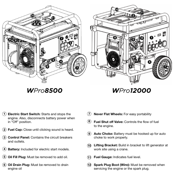
Model includes items
WPro8500 ① User Manual; ② Quick Start Guide/Maintenance Plan; ③ Lift bracket (1 piece); ④ Wireless remote control (1 unit); ⑤ 1.1L SAE 10W30 engine oil (1 bottle); ⑥ Spark plug socket wrench (1 piece); ⑦ Wheel kit accessory box; ⑧ Funnel (1 piece)
WPro12000 ① User Manual; ② Quick Start Guide/Maintenance Plan; ③ Wireless remote control (1 unit); ④ 1.6L SAE 10W30 engine oil (1 bottle); ⑤ Spark plug socket wrench (1 piece); ⑥ Wheel kit accessory box; ⑦ Funnel (1 piece)
Wheel kit accessory box: 2 washers, 4 M8 × 16mm flange bolts, 2 split pins, 2 wheel axle pins.
2. Assembly steps
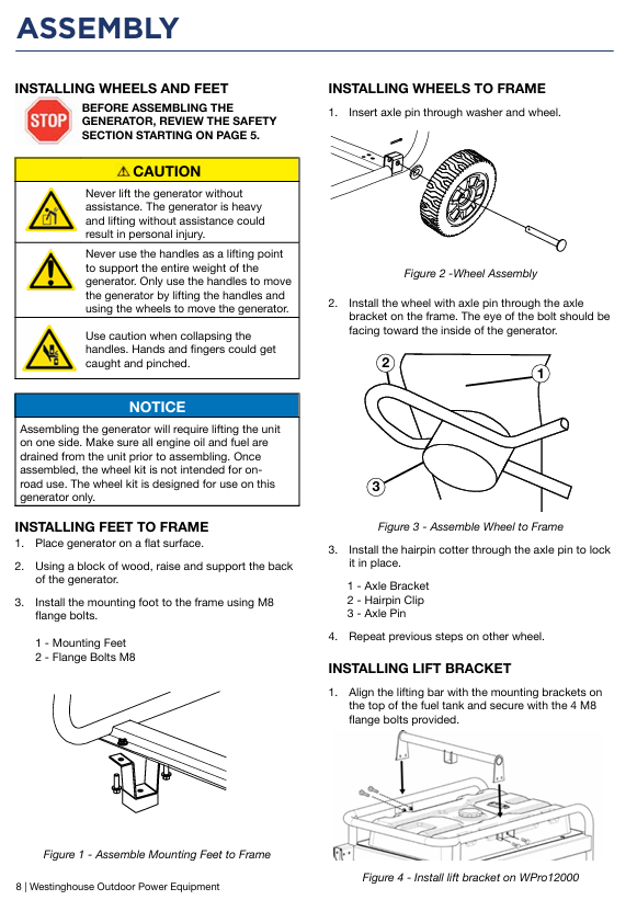
Wheel and foot installation:
Place the generator on a horizontal surface, elevate the rear with wooden blocks, and install the support feet with M8 flange bolts;
The axle pin passes through the washer and the wheel, and is installed through the frame axle bracket. The split pin is fixed, and the other side of the wheel is operated repeatedly;
Attention: Before assembly, the engine oil and fuel must be drained. The wheel kit is only applicable to this generator and is not allowed for road use.
Battery installation (key steps for preventing electric shock):
Confirm that the positive (red) cable is securely fastened to the positive pole of the battery and covered with a protective cover;
Remove the protective packaging of the negative (black) cable terminal, disconnect the cable tie and lead it to the negative pole;
Open the black sleeve, tighten the negative cable, and then put back the protective sleeve;
Rule: Connect the power first and then the negative, disconnect the power first and then the negative, prohibit metal tools from crossing the two poles, and use insulated tools for operation.
Installation of lifting bracket (WPro8500 only): Align the bracket on the top of the fuel tank and fix it with 4 M8 flange bolts.
Operation Guide
1. Preparation before startup
Location selection: Outdoor ventilation, level and solid surface, at least 6 feet (1.8 meters) away from buildings/combustibles, away from doors, windows/ventilation openings.
Environmental requirements: Do not operate on rainy/snowy days, operate on dry surfaces to avoid loose materials (sand/grass debris) blocking the air vents.
Load and grounding: Disconnect all loads (unplug extension wires) before starting; A certified electrician is required to determine whether a grounding rod is needed (usually required when connecting the backup power supply to the transfer switch), and connect the control panel grounding terminal with a ≥ 10 AWG copper wire for grounding.
2. Fuel and oil requirements
Fuel: Only use unleaded gasoline, ethanol content ≤ 10%, octane rating ≥ 87; Stop the machine for cooling before refueling, ensure that the oil level does not exceed the neck of the filling port, and check for leaks after refueling.
Engine oil: The new engine has no engine oil, and 10W30 engine oil must be added before the first start-up (5W30 in winter and SAE30 in summer); Check the liquid level of the refrigeration unit, which should be between the H (high) and L (low) marks on the dipstick.
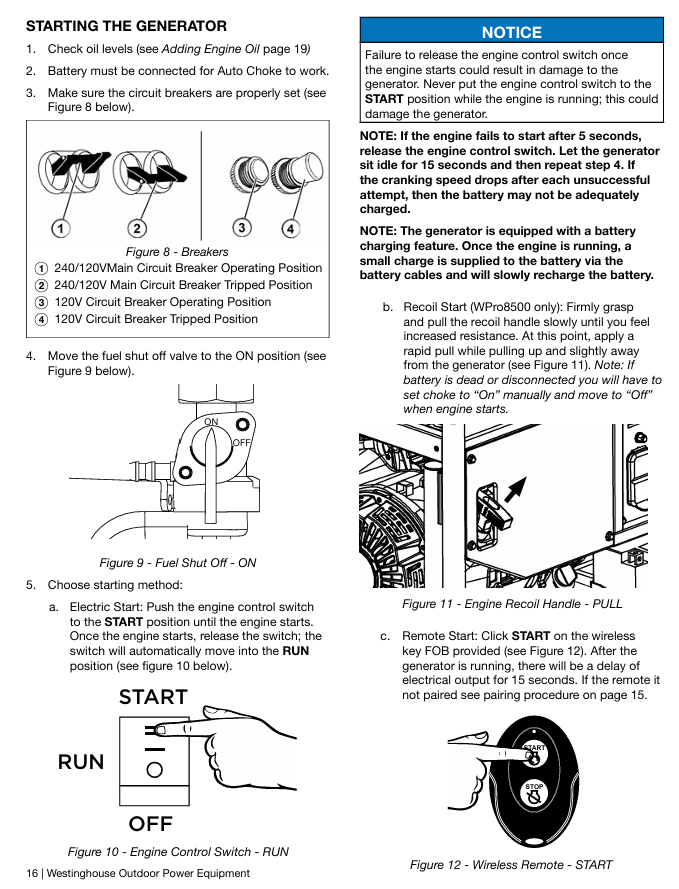
3. Startup method
Startup method, operating steps, applicable models, precautions
Electric start 1. Confirm that the engine oil is sufficient and the battery is connected; 2. Reset the circuit breaker; 3. Turn the fuel valve to ON; 4. Press the switch to START and release it after starting (automatic return to RUN). Both options are applicable. If it does not start for 5 seconds, release it and retry after 15 seconds; Charging when the battery is depleted
Backlash start 1. Same as 1-3 above; 2. Slowly pull the rope until the resistance increases, and quickly pull it upwards away from the generator. When only the WPro8500 battery runs out of power/disconnects, manually turn on the choke and turn it off after starting
Remote start 1. Turn the switch to RUN; 2. Long press the REMOTE PAIRING button on the panel for 3 seconds; 3. Long press the STOP button on the remote control until the indicator light flashes, and then long press the START button until it flashes; 4. Press and hold the PAIRING key for 3 seconds to complete pairing; 5. Press the START button on the remote control to start both models, with an effective distance of ≤ 100 feet (affected by battery level). After starting, there will be a 15 second delay in output
4. Stop method
Normal stop: 1 Disconnect all loads; 2. Cooling during no-load operation; 3. Turn the switch to OFF; 4. Close the fuel valve (allow the carburetor to run out of fuel during long-term storage).
Emergency stop: Simply turn the engine control switch to OFF.
Special maintenance operation
Oil change: When the engine is in a cold state, drain the oil from the oil pan through the oil drain plug, remove the plug and drain, then reinstall and add oil to the standard level.
Air filter cleaning: Remove the cover and take out the filter cotton, clean with household detergent and warm water, squeeze and drain (do not twist), air dry, apply a thin layer of cleaning oil, and reinstall according to the "fine filter (ash) inside, coarse filter (black) outside".
Spark plug maintenance: Remove the spark plug with a spark socket wrench, check the insulation layer for cracks and a gap of 0.027-0.032 inches (0.60-0.80mm), clean and reinstall it; Recommended replacement models: AC Delco 4EXLS, Autolite 52, Champion N9YC, Bosch W7DC, Torch F7TC.
Battery maintenance: Start the generator every 2-3 months and charge it for 15 minutes, or connect the charger to the charging port (RUN mode) for charging; The replacement model is as follows:
Model Westinghouse Part Number Compatible Battery Model Voltage (V) Capacity (Ah) Size (inches)
WPro8500 100557 YT9A 12 9 5 5/16 × 3 × 5 3/8
WPro12000 100639 YT51913-22 12 20 7 1/8 × 3 × 6 9/16
Troubleshooting
Possible causes and solutions for the problem
The engine is running but there is no power output. 1. The circuit breaker has tripped; 2. The power plug is not securely plugged in; 3. Power cord malfunction; 4. Electrical equipment malfunction; 5. GFCI trips; 6. Internal equipment malfunction: 1. Reset the circuit breaker and check for overload; 2. Re plug (the 240V plug needs to be turned clockwise by 1/4 turn); 3. Replace the power cord; 4. Connect to normal equipment testing; 5. Reset the GFCI circuit breaker; 6. Send to authorized service points
The engine cannot start/stalls after starting. 1. The fuel valve is closed; 2. Lack of gasoline; 3. Fuel pipeline blockage; 4. The startup battery runs out of power; 5. The air filter is dirty; 6. Low oil level (low oil protection); 7. Spark plug not tightened/faulty; 8. Fuel deterioration: 1. Open the fuel valve; 2. Add gasoline that meets the requirements; 3. Check and clean the fuel passage; 4. Charging (electric start only); 5. Clean/replace the air filter; 6. Add engine oil to the standard level; 7. Tighten/replace spark plugs; 8. Drain the deteriorated fuel and add new fuel
Remote start failure: 1. The remote control battery is dead; 2. Exceeding the remote control distance (>100 feet); 3. The remote control is not paired with the generator. 1. Replace the remote control battery; 2. Close to the generator (≤ 100 feet); 3. Follow the pairing process again
Sudden shutdown of generator: 1. Lack of fuel; 2. Low oil level (protective shutdown); 3. Excessive load; 4. Internal equipment malfunction: 1. Add gasoline; 2. Add engine oil; 3. Reduce load after restart; 4. Send to authorized service points
Product drawings
Explosion view: WPro8500 (page 26), WPro12000 (page 31) complete machine parts breakdown, including part numbers and names (such as generator assembly, fuel tank, control panel, etc.).
Engine view: Position markings and part numbers for the internal structures (pistons, connecting rods, valves, ignition coils, etc.) of two engine models.
Schematic diagram: Schematic diagram of electrical system (voltage regulator, wiring harness), fuel system (carbon canister, oil pipe) and other connections.
- OMRON
- ABB
- General Electric
- EMERSON
- Honeywell
- HIMA
- ALSTOM
- Rolls-Royce
- MOTOROLA
- Rockwell
- Siemens
- Woodward
- YOKOGAWA
- FOXBORO
- KOLLMORGEN
- MOOG
- KB
- YAMAHA
- BENDER
- TEKTRONIX
- Westinghouse
- AMAT
- AB
- XYCOM
- Yaskawa
- B&R
- Schneider
- KONGSBERG
- NI
- WATLOW
- ProSoft
- SEW
- ADVANCED
- Reliance
- TRICONEX
- METSO
- MAN
- Advantest
- STUDER
- DANAHER MOTION
- Bently
- Galil
- EATON
- MOLEX
- DEIF
- B&W
- ZYGO
- Aerotech
- DANFOSS
- Beijer
- Moxa
- Rexroth
- Johnson
- WAGO
- TOSHIBA
- BMCM
- SMC
- HITACHI
- HIRSCHMANN
- Application field
- XP POWER
- CTI
- TRICON
- STOBER
- Thinklogical
- Horner Automation
- Meggitt
- Fanuc
- Baldor
- SHINKAWA
- Other Brands
- UniOP
- KUKA
- Iba
- Beckhoff
-
 Basler D90 96801 100 PCB Card
 -
 Basler XR2002F Voltage Regulator (110 VAC, 48-480 Hz)
 -
 Basler SR8A-2B14B3A Regulator
 -
 Basler 9561500100 Module
 -
 Basler DECS-400 BE1-11 System
 -
 Basler DECS-100-B15 Excitation Control
 -
 Basler SCP 210 Frequency Controller
 -
 Basler SR4A-2B15B3A Static Voltage Regulator
 -
 Basler BE1-32R Power Relay
 -
 Basler PIA2400-17GM Power Interface Adapter
 -
 Basler MVC 232 Manual Voltage Control Module
 -
 Basler SSR 32-12 Static Voltage Regulator
 -
 Basler 5MW AVR Generator Voltage Regulator
 -
 Basler VR63-4B Voltage Regulator
 -
 Basler DECS-100-A05 AVR for Engine Generator
 -
 Basler DECS-100-B15 Automatic Voltage Regulator
 -
 Basler BE1-32R Directional Power Relay
 -
 Basler BE1-87B Differential Relay
 -
 Basler UFOV 260A Protective Module
 -
 Basler 9-2614-02-100 PCB Rev M
 -
Basler DECS-100-B15 Digital AVR
-
 Basler 9284900103 PS DECS-400N
 -
 Basler D4N3H1U Intertie Protection
 -
 Basler DECS-100-B15 A15 AVR
 -
 Basler KR4F Voltage Regulator
 -
 Basler BE26434 T14 Transformer
 -
 Basler SR8A-2B15B3A Regulator
 -
 Westinghouse 774B472A12 AR Relay
 -
Basler DECS-100-B15 AVR
-
Basler XR2002F Regulator 110V
-
Basler SR125-E Static Regulator
-
 Basler SSR 125-12 Regulator
 -
 Basler MOC2599 Motor Pot
 -
 Basler BE1-DFPR Feeder Relay
 -
 Basler CBS 305 Current Boost
 -
 Basler BE1-25 AutoSync
 -
 Basler MVC 300 Voltage Control
 -
 Basler BE3-25A AutoSync
 -
 Basler KR7FF Static Regulator
 -
 Basler 90-49000-100 Regulator
 -
 Basler 880 kVA Dry Type Transformer Specs
 -
 Basler Electric BE1-25 Sync-Check Relay Specs
 -
 Basler SSR 125-12 Voltage Regulator Specs
 -
 Basler Electric BE1-851 Overcurrent Relay Review
 -
Basler Electric 149D930G02 Control Sub-Assembly
-
 Basler Electric BE1-81O/UT Frequency Relay Specs
 -
 Basler Electric BE1-51/27C Overcurrent Relay
 -
 Basler Electric 149D956G02 Industrial Component
 -
Basler Electric BE1-51A Overcurrent Relay Specs
-
 Basler Electric BE1-40Q Loss of Excitation Relay
 -
 Basler DECS-200 Excitation Control System
 -
 Basler DECS-200 Voltage Regulator 56-277V AC / 125V DC
 -
Basler BE1-87T Transformer Differential Relay
-
 Basler RDP-110-S1 Protection Relay
 -
 Basler BE1-700V Digital Protective Relay
 -
 Basler BE1-951 Overcurrent Protection System
 -
 Basler DECS-300 Digital Excitation Control
 -
 Basler DECS-200 Digital Excitation Control
 -
 Basler DECS-200-1C Excitation Control System
 -
Basler DECS-200-1L Digital Excitation Control
-
 Basler Electric BE1-GPS Generator Protection System
 -
Basler Electric DECS-200-1C Digital Excitation Controller
-
 Basler Electric DECS125-15 Excitation Control with Power Module
 -
 Basler Electric BE1-87G Differential Relay
 -
 Basler Electric BE1-11 Protection System I5A3M2P2N0EA00
 -
Basler Electric DECS-200-1C Excitation Control System
-
Basler Electric BE1-11g Generator Protection Relay
-
Basler Electric DECS 125-15-B2C1 V2.0.9 Excitation Control
-
 Basler Electric BE1-81O/UT3ED1JA7N2F Frequency Relay
 -
Basler Electric BE1-81O/UT3EE1YB7N1F Frequency Relay
-
 Basler Electric DECS-200-1L Digital Excitation Control System
 -
Basler DECS125-15-B2C1 Excitation Control
-
 Basler 9507900205 SSR Retrofit Voltage Regulator
 -
 Basler BE2000E Digital Voltage Regulator
 -
 Basler BE1-GPS Generator Protection System
 -
Basler DECS-250-CN1CN1N Digital Excitation Control
-
 Basler DGC-2020 Genset Controller
 -
 Basler BE1-81O UT3ED1LA7N0F Frequency Relay (Variant)
 -
 Basler BE1-81O UT3EE1YA9S0F Frequency Relay (Variant)
 -
Basler BE1-81O Over/Under Frequency Relay
-
Basler DECS125-15 Digital Excitation Control
-
Basler Electric BE1-951 Overcurrent Protection System
-
 Basler Electric BE1-700V Digital Protective Relay
 -
 Basler Electric APR63-5 Automatic Voltage Regulator
 -
Basler Electric BE1-851 Overcurrent Protection System
-
Basler Electric DECS-250-LN1SN1N Excitation Control
-
 Basler Electric BE1-87T Transformer Differential Relay
 -
Basler Electric DECS-200-1L Excitation Control System
-
 Basler Electric 9310300100 DECS-300 Excitation Control
 -
 Basler Electric SSE-N 125-4.5KW Shunt Exciter Regulator
 -
 Basler Electric DGC-2020HD-5NS1DNSBA Genset Controller
 -
Basler Electric BE1-81-O/UT3EE1JB7N1F Frequency Relay
-
Basler Electric BE1-81T1EE1WA0N1F Frequency Relay
-
 Basler Electric BE1-25M1EA6PN5R1F Sync-Check Relay
 -
 Basler Electric BE1-GPS Generator Protection System
 -
Basler Electric DECS-250-LN1SN1N Excitation Control Rev V
-
 Basler Electric DECS-250-CN2CN1N Excitation Control
 -
Basler Electric BE1-50/51B-207 Overcurrent Relay
-
Basler Electric DECS-300-C0N0 Excitation Control System
-
Basler Electric DECS-200 Digital Excitation Control System
-
Basler Electric DECS-250-LN1CN1N Excitation Unit
-
Basler Electric DECS-250 LN2SA1D Excitation Unit Specs
-
Basler Electric BE1-87T Transformer Relay Review
-
Basler Electric BE1-11 Protection System
-
Basler Electric BE1-GPS100-E4N1H1N Protection System
-
 Allen-Bradley 442G-MABH-R Safety Module
 -
 Beckhoff CX1030-0111 PLC Assembly Profile
 -
 FANUC IC693CPU364 PLC Module
 -
 Orange Denmark Type 200816 220 PLC Specs
 -
 OMRON C200H-SNT31 Sysmac PLC Module
 -
 Allen Bradley 20AB022A3AYNANC0 PowerFlex 70
 -
 OMRON C200HW-PCU01 Position Control Unit
 -
 ABB AO845A-eA Analog Output Module
 -
 OMRON CJ1M-CPU22 CPU Unit
 -
 Allen Bradley 100-E265ED11 Contactor
 -
 Honeywell 51304511-100 Interface Module
 -
 SOLEXY BXF3S0101N0018 Gateway Module
 -
 OMRON CJ2H-CPU65 CPU Unit
 -
 Automation Direct GS2-45P0 AC Drive
 -
 M68-2000 2-Axis Motion CNC Controller
 -
 OMRON CJ1M-CPU11 V3.0 PLC CPU Unit
 -
 OMRON CJ1W-NC413 4-Axis Positioning Controller
 -
 OMRON 3G2A3-PRO16 Programming Console HMI
 -
 Siemens 3VT8440-2AA04-2GA2 Molded Case Circuit Breaker
 -
 Siemens 3RT5045 Contactor Series
 -
 OMRON C200HS-CPU01-E SYSMAC PLC Controller
 -
 OMRON C500-NC103-E Positioning Control Unit
 -
 OMRON CJ1W-TC001 Temperature Control Unit


