
How to unpack and install the Zygo Mark II 4-inch interferometer system?
Video monitor: Display real-time interference patterns collected by the host, 9-inch diagonal screen, equipped with a universal bracket, can be placed on the desktop or installed above the host through a dedicated lifting bracket, supporting flexible adjustment of viewing angle to optimize observation effect.
Optional VP-2 video printer: uses specially coated paper to provide hard copy recording of interference fringe patterns for easy archiving and analysis.
How to unpack and install the Zygo Mark II 4-inch interferometer system?
System composition and technical parameters
(1) System core module
Mark II host: The core function is to collect real-time interference patterns, including a 632.8nm circularly polarized output HeNe laser (replaceable on site), laser power supply, beam splitter spatial filter (BDSF), CCTV camera, and a sealed optical cabin to protect precision optical components. It is equipped with accessory sockets (for installing transmission components) and a remote control box (connected by cables).
Video monitor: Display real-time interference patterns collected by the host, 9-inch diagonal screen, equipped with a universal bracket, can be placed on the desktop or installed above the host through a dedicated lifting bracket, supporting flexible adjustment of viewing angle to optimize observation effect.
Optional VP-2 video printer: uses specially coated paper to provide hard copy recording of interference fringe patterns for easy archiving and analysis.
(2) Key technical parameters
Specific parameters of the module
Mark II host aperture: 4-inch diameter, capable of continuous zoom up to 2/3 inch (6x zoom range); Alignment: Automatic alignment and fast stripe acquisition system; Video output: 520 lines/60Hz (EIA RS170 standard) or 625 lines/50Hz (CCIR standard), 2:1 interlaced scanning, BNC interface, synchronous signal including horizontal and vertical; Dimensions: 648mm x 533mm x 203mm (length x width x height); Weight: 34kg; Power supply: 115 ± 10VAC/60Hz, 110 ± 10VAC/50Hz, or 230 ± 10VAC/50Hz, 50W without monitor, 85W with monitor (single-phase)
Video monitor screen: 9-inch diagonal; Interface: BNC type; Synchronization: Built in; Video input: Supports 75 Ω or high impedance terminals; Power supply: 115 ± 10VAC/60Hz, 300mA; Dimensions: 311mm x 229mm x 241mm (length x width x height); Weight: 6.35kg
Laser Radiation Safety Regulations
Laser characteristics and risk warning: The host emits visible red light, with no harmful invisible radiation. The radiation power is less than 1 milliwatt (1/1000 watt), the wavelength is 632.8nm, and the irradiation time exceeds 0.25 seconds. It cannot burn or drill holes, but it is necessary to avoid direct viewing of the beam and strong light reflection to prevent eye damage. Skin contact is not harmful.
Classification and compliance standards: Complies with ANSI Z136.1-1980 standard and belongs to "low-power Class II laser"; Comply with the regulations of the National Center for Devices and Radiological Health (NCDRH) under the US Food and Drug Administration (FDA) effective August 2, 1976 (for laser products manufactured after August 1, 1976), and meet the DHHS radiation performance standards (21CFR Chapter 1, Subcapter J).
Safe operation and identification
Control usage: Only operate control buttons, adjust parameters, or execute procedures as specified in the manual. Violation may result in hazardous radiation exposure.
Key components: The front panel of the host has a green radiation emission indicator light (which lights up when turned on and indicates Class II radiation), and a "BEAM ATTEN." beam attenuation knob (pull out to turn off the laser, push in to turn on); The laser head and power supply need to use Zygo original accessories, and replacement should follow the process outlined in Service Manual SP-0038 to ensure compliance with federal radiation standards.
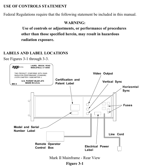
Identification location: There are certification and patent labels (US Patent No. 4201473) and model serial number labels on the back of the host; At the top (when installing the aperture converter), there is a sign that reads "Laser radiation is emitted from this aperture to avoid exposure"; After opening the lid, there are labels such as "Damaged Seal Invalid Warranty", "High Voltage Warning", "Laser Radiation When Opening, Avoid Direct Exposure" (see Figures 3-1 to 3-3).
Unpacking and installation setup
(1) Installation environment and equipment placement
Stability requirement: The host is recommended to be placed on an optical workbench (such as a granite or honeycomb air cushion platform), with a horizontal beam emitted from the right side of the equipment, making it easy to place the test piece and auxiliary components on the same platform and flexibly adapting to various testing scenarios.
Installation flexibility: In addition to the standard horizontal beam setup, the host can be installed with vertical upward/downward light output; The remote control box and movable monitor enable the host position to be optimized independently of the testing setup, suitable for laboratory prototype development, production testing, and other scenarios. It can also support multiple sets of testing setups on one host through the use of a MUX cube or mobile host.
(2) Unpacking and Inspection
System inventory: The packaging box should include the host, video monitor with bracket, lifting bracket and accessories (hardware, monitor power cord, BNC coaxial line), "Interference Pattern Interpretation and Evaluation Manual" (including mechanical parallelogram), acquisition target, "Operation and Maintenance Manual OMP-0055", "Service Manual SP-0038"; If the packaging box is damaged, please contact the shipping party immediately.
- OMRON
- ABB
- General Electric
- EMERSON
- Honeywell
- HIMA
- ALSTOM
- Rolls-Royce
- MOTOROLA
- Rockwell
- Siemens
- Woodward
- YOKOGAWA
- FOXBORO
- KOLLMORGEN
- MOOG
- KB
- YAMAHA
- BENDER
- TEKTRONIX
- Westinghouse
- AMAT
- AB
- XYCOM
- Yaskawa
- B&R
- Schneider
- KONGSBERG
- NI
- WATLOW
- ProSoft
- SEW
- ADVANCED
- Reliance
- TRICONEX
- METSO
- MAN
- Advantest
- STUDER
- DANAHER MOTION
- Bently
- Galil
- EATON
- MOLEX
- DEIF
- B&W
- ZYGO
- Aerotech
- DANFOSS
- Beijer
- Moxa
- Rexroth
- Johnson
- WAGO
- TOSHIBA
- BMCM
- SMC
- HITACHI
- HIRSCHMANN
- Application field
- XP POWER
- CTI
- TRICON
- STOBER
- Thinklogical
- Horner Automation
- Meggitt
- Fanuc
- Baldor
- SHINKAWA
- Other Brands
- UniOP
- KUKA
- Iba
- Beckhoff
-
 Basler D90 96801 100 PCB Card
 -
 Basler XR2002F Voltage Regulator (110 VAC, 48-480 Hz)
 -
 Basler SR8A-2B14B3A Regulator
 -
 Basler 9561500100 Module
 -
 Basler DECS-400 BE1-11 System
 -
 Basler DECS-100-B15 Excitation Control
 -
 Basler SCP 210 Frequency Controller
 -
 Basler SR4A-2B15B3A Static Voltage Regulator
 -
 Basler BE1-32R Power Relay
 -
 Basler PIA2400-17GM Power Interface Adapter
 -
 Basler MVC 232 Manual Voltage Control Module
 -
 Basler SSR 32-12 Static Voltage Regulator
 -
 Basler 5MW AVR Generator Voltage Regulator
 -
 Basler VR63-4B Voltage Regulator
 -
 Basler DECS-100-A05 AVR for Engine Generator
 -
 Basler DECS-100-B15 Automatic Voltage Regulator
 -
 Basler BE1-32R Directional Power Relay
 -
 Basler BE1-87B Differential Relay
 -
 Basler UFOV 260A Protective Module
 -
 Basler 9-2614-02-100 PCB Rev M
 -
Basler DECS-100-B15 Digital AVR
-
 Basler 9284900103 PS DECS-400N
 -
 Basler D4N3H1U Intertie Protection
 -
 Basler DECS-100-B15 A15 AVR
 -
 Basler KR4F Voltage Regulator
 -
 Basler BE26434 T14 Transformer
 -
 Basler SR8A-2B15B3A Regulator
 -
 Westinghouse 774B472A12 AR Relay
 -
Basler DECS-100-B15 AVR
-
Basler XR2002F Regulator 110V
-
Basler SR125-E Static Regulator
-
 Basler SSR 125-12 Regulator
 -
 Basler MOC2599 Motor Pot
 -
 Basler BE1-DFPR Feeder Relay
 -
 Basler CBS 305 Current Boost
 -
 Basler BE1-25 AutoSync
 -
 Basler MVC 300 Voltage Control
 -
 Basler BE3-25A AutoSync
 -
 Basler KR7FF Static Regulator
 -
 Basler 90-49000-100 Regulator
 -
 Basler 880 kVA Dry Type Transformer Specs
 -
 Basler Electric BE1-25 Sync-Check Relay Specs
 -
 Basler SSR 125-12 Voltage Regulator Specs
 -
 Basler Electric BE1-851 Overcurrent Relay Review
 -
Basler Electric 149D930G02 Control Sub-Assembly
-
 Basler Electric BE1-81O/UT Frequency Relay Specs
 -
 Basler Electric BE1-51/27C Overcurrent Relay
 -
 Basler Electric 149D956G02 Industrial Component
 -
Basler Electric BE1-51A Overcurrent Relay Specs
-
 Basler Electric BE1-40Q Loss of Excitation Relay
 -
 Basler DECS-200 Excitation Control System
 -
 Basler DECS-200 Voltage Regulator 56-277V AC / 125V DC
 -
Basler BE1-87T Transformer Differential Relay
-
 Basler RDP-110-S1 Protection Relay
 -
 Basler BE1-700V Digital Protective Relay
 -
 Basler BE1-951 Overcurrent Protection System
 -
 Basler DECS-300 Digital Excitation Control
 -
 Basler DECS-200 Digital Excitation Control
 -
 Basler DECS-200-1C Excitation Control System
 -
Basler DECS-200-1L Digital Excitation Control
-
 Basler Electric BE1-GPS Generator Protection System
 -
Basler Electric DECS-200-1C Digital Excitation Controller
-
 Basler Electric DECS125-15 Excitation Control with Power Module
 -
 Basler Electric BE1-87G Differential Relay
 -
 Basler Electric BE1-11 Protection System I5A3M2P2N0EA00
 -
Basler Electric DECS-200-1C Excitation Control System
-
Basler Electric BE1-11g Generator Protection Relay
-
Basler Electric DECS 125-15-B2C1 V2.0.9 Excitation Control
-
 Basler Electric BE1-81O/UT3ED1JA7N2F Frequency Relay
 -
Basler Electric BE1-81O/UT3EE1YB7N1F Frequency Relay
-
 Basler Electric DECS-200-1L Digital Excitation Control System
 -
Basler DECS125-15-B2C1 Excitation Control
-
 Basler 9507900205 SSR Retrofit Voltage Regulator
 -
 Basler BE2000E Digital Voltage Regulator
 -
 Basler BE1-GPS Generator Protection System
 -
Basler DECS-250-CN1CN1N Digital Excitation Control
-
 Basler DGC-2020 Genset Controller
 -
 Basler BE1-81O UT3ED1LA7N0F Frequency Relay (Variant)
 -
 Basler BE1-81O UT3EE1YA9S0F Frequency Relay (Variant)
 -
Basler BE1-81O Over/Under Frequency Relay
-
Basler DECS125-15 Digital Excitation Control
-
Basler Electric BE1-951 Overcurrent Protection System
-
 Basler Electric BE1-700V Digital Protective Relay
 -
 Basler Electric APR63-5 Automatic Voltage Regulator
 -
Basler Electric BE1-851 Overcurrent Protection System
-
Basler Electric DECS-250-LN1SN1N Excitation Control
-
 Basler Electric BE1-87T Transformer Differential Relay
 -
Basler Electric DECS-200-1L Excitation Control System
-
 Basler Electric 9310300100 DECS-300 Excitation Control
 -
 Basler Electric SSE-N 125-4.5KW Shunt Exciter Regulator
 -
 Basler Electric DGC-2020HD-5NS1DNSBA Genset Controller
 -
Basler Electric BE1-81-O/UT3EE1JB7N1F Frequency Relay
-
Basler Electric BE1-81T1EE1WA0N1F Frequency Relay
-
 Basler Electric BE1-25M1EA6PN5R1F Sync-Check Relay
 -
 Basler Electric BE1-GPS Generator Protection System
 -
Basler Electric DECS-250-LN1SN1N Excitation Control Rev V
-
 Basler Electric DECS-250-CN2CN1N Excitation Control
 -
Basler Electric BE1-50/51B-207 Overcurrent Relay
-
Basler Electric DECS-300-C0N0 Excitation Control System
-
Basler Electric DECS-200 Digital Excitation Control System
-
Basler Electric DECS-250-LN1CN1N Excitation Unit
-
Basler Electric DECS-250 LN2SA1D Excitation Unit Specs
-
Basler Electric BE1-87T Transformer Relay Review
-
Basler Electric BE1-11 Protection System
-
Basler Electric BE1-GPS100-E4N1H1N Protection System
-
 Allen-Bradley 442G-MABH-R Safety Module
 -
 Beckhoff CX1030-0111 PLC Assembly Profile
 -
 FANUC IC693CPU364 PLC Module
 -
 Orange Denmark Type 200816 220 PLC Specs
 -
 OMRON C200H-SNT31 Sysmac PLC Module
 -
 Allen Bradley 20AB022A3AYNANC0 PowerFlex 70
 -
 OMRON C200HW-PCU01 Position Control Unit
 -
 ABB AO845A-eA Analog Output Module
 -
 OMRON CJ1M-CPU22 CPU Unit
 -
 Allen Bradley 100-E265ED11 Contactor
 -
 Honeywell 51304511-100 Interface Module
 -
 SOLEXY BXF3S0101N0018 Gateway Module
 -
 OMRON CJ2H-CPU65 CPU Unit
 -
 Automation Direct GS2-45P0 AC Drive
 -
 M68-2000 2-Axis Motion CNC Controller
 -
 OMRON CJ1M-CPU11 V3.0 PLC CPU Unit
 -
 OMRON CJ1W-NC413 4-Axis Positioning Controller
 -
 OMRON 3G2A3-PRO16 Programming Console HMI
 -
 Siemens 3VT8440-2AA04-2GA2 Molded Case Circuit Breaker
 -
 Siemens 3RT5045 Contactor Series
 -
 OMRON C200HS-CPU01-E SYSMAC PLC Controller
 -
 OMRON C500-NC103-E Positioning Control Unit
 -
 OMRON CJ1W-TC001 Temperature Control Unit


