
How to unpack and install the Zygo Mark II 4-inch interferometer system?
Video monitor: Display real-time interference patterns collected by the host, 9-inch diagonal screen, equipped with a universal bracket, can be placed on the desktop or installed above the host through a dedicated lifting bracket, supporting flexible adjustment of viewing angle to optimize observation effect.
Optional VP-2 video printer: uses specially coated paper to provide hard copy recording of interference fringe patterns for easy archiving and analysis.
Unpacking operation: Unpacking in a clean and dry area requires two people to lift the main unit from the bottom of both ends and remove it. It is forbidden to pull or tug on the outer shell; Before removing all items, do not discard reusable packaging boxes (it is recommended to keep them for return); Cushioning materials such as foam shall be used to prevent shock during handling to avoid severe impact.
(3) Connection and switch settings
Cable connection: Connect the BNC cable according to Figure 4-1 (host monitor) and Figure 4-2 (host monitor printer); The default factory setting for the CCTV camera jumper in the host is "output synchronization", which does not require adjustment.
Power and parameters: Insert the monitor power cord into any auxiliary power outlet on the back of the host; Confirm that the position of the "75 Ω/HI-Z" switch on the monitor is correct (see Figure 4-1/4-2); The host power cord should be connected to a power source that meets the requirements of the electrical label on the back. It is recommended to use a three hole socket with neutral grounding.
Operation process
(1) Preparation before operation
Safety prerequisite: It is necessary to read Chapter 3 "Laser Radiation Safety Information" before operating the host.
Equipment preheating: After turning on, the host and monitor need to be preheated for at least 30 minutes to ensure stable performance.
Familiarity with controls: Clearly define the functions of each button on the host and remote control box (such as the power switch, beam attenuation knob, and accessory socket tilt adjustment knob on the host; the fast stripe acquisition switch and zoom/focus adjustment switch on the remote box).
(2) Core operational steps
Boot startup
Confirm that the front beam attenuation knob of the host is pushed in, turn on the power switch, and the laser should start within 30 seconds. If it does not start, refer to the troubleshooting section of Service Manual SP-0038; There is a slow melting fuse on the back of the host (see Chapter 6 "Fuse Specifications" for the model).
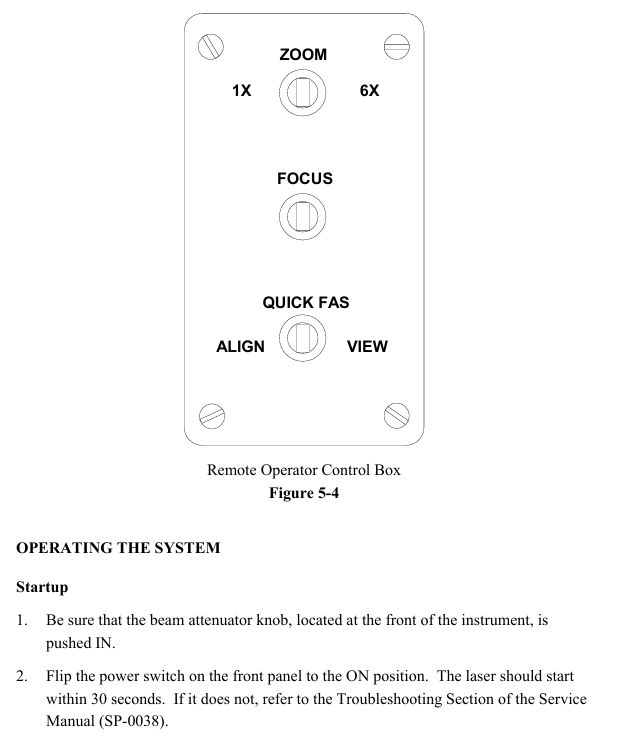
Remote control box operation (see Figure 5-4)
Quick FAS switch: Center off, left dial "ALIGN" (alignment mode, hold for about 2 seconds, monitor displays aligned spot and automatic alignment crosshair), right dial "VIEW" (observation mode, hold for about 2 seconds, display interference pattern).
Zoom adjustment: With the center closed, it can achieve 6x continuous magnification (corresponding to aperture diameter for planar testing and f-number for spherical/cylindrical testing).
Focus adjustment: Center off, operate at 6x (or close to 6x) zoom, hold down the left and right keys, observe the edges of the test piece or small objects inserted into the beam (such as pen tips) until the outline is clearest (the stripes are not bent at the edges and are sharply truncated), do not directly focus on the stripes (their width is determined by the illumination intensity and needs to be adjusted by the monitor brightness/contrast).
Installation and alignment of transmission components
Universal installation: For transmissive components (flat or spherical), hold the metal edge in hand (do not touch the glass), loosen the spring clip screw of the accessory socket, insert the short metal pin of the component into the socket slot, and then rotate clockwise until it clicks into place. Finally, tighten the spring clip screw.
Alignment of transmission plane: After turning on the remote box, dial "ALIGN" for about 2 seconds, and the monitor will display a crosshair and two light spots (the bright spots are reflected by the uncoated surface of the transmission plane). Adjust the two tilt knobs of the accessory socket to make the bright spots coincide with the center of the crosshair.
Transmission sphere alignment: Remote box dial "ALIGN" for about 2 seconds, the monitor displays a crosshair and a light spot (reflected by the transmission element surface), adjust the tilt knob to make the light spot coincide with the center of the crosshair; Place the test piece (or 4% reflectivity concave convex surface) at the focal point of the converging beam of the transmissive element, and move the test piece so that the curvature center coincides with the focal point of the transmissive sphere (the bright spot converges at the center of the crosshair and disappears); Switch the "VIEW" mode. If the bull's-eye pattern displayed by the monitor is offset, use the X/Y knob of the 3/5 axis bracket to center (do not move the tilt knob of the host), and then focus through the Z axis knob (push the movement direction of the observation ring on the back of the bracket: move the Z axis clockwise when moving toward the center, and counterclockwise when moving outward). Finally, adjust the X/Y knob at the socket end of the transmission element to control the number of stripes to 0-7 (the best observation effect).
Installation and alignment of aperture converter
Preliminary preparation: Remove the transmission component from the accessory socket of the host, place a flat reflector with two axis brackets (reference or transmission plane) in the laser light path (about 45.7cm away from the host), and align the reflector using the "transmission plane alignment" process (this alignment state needs to be maintained).
- OMRON
- ABB
- General Electric
- EMERSON
- Honeywell
- HIMA
- ALSTOM
- Rolls-Royce
- MOTOROLA
- Rockwell
- Siemens
- Woodward
- YOKOGAWA
- FOXBORO
- KOLLMORGEN
- MOOG
- KB
- YAMAHA
- BENDER
- TEKTRONIX
- Westinghouse
- AMAT
- AB
- XYCOM
- Yaskawa
- B&R
- Schneider
- KONGSBERG
- NI
- WATLOW
- ProSoft
- SEW
- ADVANCED
- Reliance
- TRICONEX
- METSO
- MAN
- Advantest
- STUDER
- DANAHER MOTION
- Bently
- Galil
- EATON
- MOLEX
- DEIF
- B&W
- ZYGO
- Aerotech
- DANFOSS
- Beijer
- Moxa
- Rexroth
- Johnson
- WAGO
- TOSHIBA
- BMCM
- SMC
- HITACHI
- HIRSCHMANN
- Application field
- XP POWER
- CTI
- TRICON
- STOBER
- Thinklogical
- Horner Automation
- Meggitt
- Fanuc
- Baldor
- SHINKAWA
- Other Brands
- UniOP
- KUKA
- Iba
- Beckhoff
-
 Basler D90 96801 100 PCB Card
 -
 Basler XR2002F Voltage Regulator (110 VAC, 48-480 Hz)
 -
 Basler SR8A-2B14B3A Regulator
 -
 Basler 9561500100 Module
 -
 Basler DECS-400 BE1-11 System
 -
 Basler DECS-100-B15 Excitation Control
 -
 Basler SCP 210 Frequency Controller
 -
 Basler SR4A-2B15B3A Static Voltage Regulator
 -
 Basler BE1-32R Power Relay
 -
 Basler PIA2400-17GM Power Interface Adapter
 -
 Basler MVC 232 Manual Voltage Control Module
 -
 Basler SSR 32-12 Static Voltage Regulator
 -
 Basler 5MW AVR Generator Voltage Regulator
 -
 Basler VR63-4B Voltage Regulator
 -
 Basler DECS-100-A05 AVR for Engine Generator
 -
 Basler DECS-100-B15 Automatic Voltage Regulator
 -
 Basler BE1-32R Directional Power Relay
 -
 Basler BE1-87B Differential Relay
 -
 Basler UFOV 260A Protective Module
 -
 Basler 9-2614-02-100 PCB Rev M
 -
Basler DECS-100-B15 Digital AVR
-
 Basler 9284900103 PS DECS-400N
 -
 Basler D4N3H1U Intertie Protection
 -
 Basler DECS-100-B15 A15 AVR
 -
 Basler KR4F Voltage Regulator
 -
 Basler BE26434 T14 Transformer
 -
 Basler SR8A-2B15B3A Regulator
 -
 Westinghouse 774B472A12 AR Relay
 -
Basler DECS-100-B15 AVR
-
Basler XR2002F Regulator 110V
-
Basler SR125-E Static Regulator
-
 Basler SSR 125-12 Regulator
 -
 Basler MOC2599 Motor Pot
 -
 Basler BE1-DFPR Feeder Relay
 -
 Basler CBS 305 Current Boost
 -
 Basler BE1-25 AutoSync
 -
 Basler MVC 300 Voltage Control
 -
 Basler BE3-25A AutoSync
 -
 Basler KR7FF Static Regulator
 -
 Basler 90-49000-100 Regulator
 -
 Basler 880 kVA Dry Type Transformer Specs
 -
 Basler Electric BE1-25 Sync-Check Relay Specs
 -
 Basler SSR 125-12 Voltage Regulator Specs
 -
 Basler Electric BE1-851 Overcurrent Relay Review
 -
Basler Electric 149D930G02 Control Sub-Assembly
-
 Basler Electric BE1-81O/UT Frequency Relay Specs
 -
 Basler Electric BE1-51/27C Overcurrent Relay
 -
 Basler Electric 149D956G02 Industrial Component
 -
Basler Electric BE1-51A Overcurrent Relay Specs
-
 Basler Electric BE1-40Q Loss of Excitation Relay
 -
 Basler DECS-200 Excitation Control System
 -
 Basler DECS-200 Voltage Regulator 56-277V AC / 125V DC
 -
Basler BE1-87T Transformer Differential Relay
-
 Basler RDP-110-S1 Protection Relay
 -
 Basler BE1-700V Digital Protective Relay
 -
 Basler BE1-951 Overcurrent Protection System
 -
 Basler DECS-300 Digital Excitation Control
 -
 Basler DECS-200 Digital Excitation Control
 -
 Basler DECS-200-1C Excitation Control System
 -
Basler DECS-200-1L Digital Excitation Control
-
 Basler Electric BE1-GPS Generator Protection System
 -
Basler Electric DECS-200-1C Digital Excitation Controller
-
 Basler Electric DECS125-15 Excitation Control with Power Module
 -
 Basler Electric BE1-87G Differential Relay
 -
 Basler Electric BE1-11 Protection System I5A3M2P2N0EA00
 -
Basler Electric DECS-200-1C Excitation Control System
-
Basler Electric BE1-11g Generator Protection Relay
-
Basler Electric DECS 125-15-B2C1 V2.0.9 Excitation Control
-
 Basler Electric BE1-81O/UT3ED1JA7N2F Frequency Relay
 -
Basler Electric BE1-81O/UT3EE1YB7N1F Frequency Relay
-
 Basler Electric DECS-200-1L Digital Excitation Control System
 -
Basler DECS125-15-B2C1 Excitation Control
-
 Basler 9507900205 SSR Retrofit Voltage Regulator
 -
 Basler BE2000E Digital Voltage Regulator
 -
 Basler BE1-GPS Generator Protection System
 -
Basler DECS-250-CN1CN1N Digital Excitation Control
-
 Basler DGC-2020 Genset Controller
 -
 Basler BE1-81O UT3ED1LA7N0F Frequency Relay (Variant)
 -
 Basler BE1-81O UT3EE1YA9S0F Frequency Relay (Variant)
 -
Basler BE1-81O Over/Under Frequency Relay
-
Basler DECS125-15 Digital Excitation Control
-
Basler Electric BE1-951 Overcurrent Protection System
-
 Basler Electric BE1-700V Digital Protective Relay
 -
 Basler Electric APR63-5 Automatic Voltage Regulator
 -
Basler Electric BE1-851 Overcurrent Protection System
-
Basler Electric DECS-250-LN1SN1N Excitation Control
-
 Basler Electric BE1-87T Transformer Differential Relay
 -
Basler Electric DECS-200-1L Excitation Control System
-
 Basler Electric 9310300100 DECS-300 Excitation Control
 -
 Basler Electric SSE-N 125-4.5KW Shunt Exciter Regulator
 -
 Basler Electric DGC-2020HD-5NS1DNSBA Genset Controller
 -
Basler Electric BE1-81-O/UT3EE1JB7N1F Frequency Relay
-
Basler Electric BE1-81T1EE1WA0N1F Frequency Relay
-
 Basler Electric BE1-25M1EA6PN5R1F Sync-Check Relay
 -
 Basler Electric BE1-GPS Generator Protection System
 -
Basler Electric DECS-250-LN1SN1N Excitation Control Rev V
-
 Basler Electric DECS-250-CN2CN1N Excitation Control
 -
Basler Electric BE1-50/51B-207 Overcurrent Relay
-
Basler Electric DECS-300-C0N0 Excitation Control System
-
Basler Electric DECS-200 Digital Excitation Control System
-
Basler Electric DECS-250-LN1CN1N Excitation Unit
-
Basler Electric DECS-250 LN2SA1D Excitation Unit Specs
-
Basler Electric BE1-87T Transformer Relay Review
-
Basler Electric BE1-11 Protection System
-
Basler Electric BE1-GPS100-E4N1H1N Protection System
-
 Allen-Bradley 442G-MABH-R Safety Module
 -
 Beckhoff CX1030-0111 PLC Assembly Profile
 -
 FANUC IC693CPU364 PLC Module
 -
 Orange Denmark Type 200816 220 PLC Specs
 -
 OMRON C200H-SNT31 Sysmac PLC Module
 -
 Allen Bradley 20AB022A3AYNANC0 PowerFlex 70
 -
 OMRON C200HW-PCU01 Position Control Unit
 -
 ABB AO845A-eA Analog Output Module
 -
 OMRON CJ1M-CPU22 CPU Unit
 -
 Allen Bradley 100-E265ED11 Contactor
 -
 Honeywell 51304511-100 Interface Module
 -
 SOLEXY BXF3S0101N0018 Gateway Module
 -
 OMRON CJ2H-CPU65 CPU Unit
 -
 Automation Direct GS2-45P0 AC Drive
 -
 M68-2000 2-Axis Motion CNC Controller
 -
 OMRON CJ1M-CPU11 V3.0 PLC CPU Unit
 -
 OMRON CJ1W-NC413 4-Axis Positioning Controller
 -
 OMRON 3G2A3-PRO16 Programming Console HMI
 -
 Siemens 3VT8440-2AA04-2GA2 Molded Case Circuit Breaker
 -
 Siemens 3RT5045 Contactor Series
 -
 OMRON C200HS-CPU01-E SYSMAC PLC Controller
 -
 OMRON C500-NC103-E Positioning Control Unit
 -
 OMRON CJ1W-TC001 Temperature Control Unit


