
How to unpack and install the Zygo Mark II 4-inch interferometer system?
Video monitor: Display real-time interference patterns collected by the host, 9-inch diagonal screen, equipped with a universal bracket, can be placed on the desktop or installed above the host through a dedicated lifting bracket, supporting flexible adjustment of viewing angle to optimize observation effect.
Optional VP-2 video printer: uses specially coated paper to provide hard copy recording of interference fringe patterns for easy archiving and analysis.
How to unpack and install the Zygo Mark II 4-inch interferometer system?
System composition and technical parameters
(1) System core module
Mark II host: The core function is to collect real-time interference patterns, including a 632.8nm circularly polarized output HeNe laser (replaceable on site), laser power supply, beam splitter spatial filter (BDSF), CCTV camera, and a sealed optical cabin to protect precision optical components. It is equipped with accessory sockets (for installing transmission components) and a remote control box (connected by cables).
Video monitor: Display real-time interference patterns collected by the host, 9-inch diagonal screen, equipped with a universal bracket, can be placed on the desktop or installed above the host through a dedicated lifting bracket, supporting flexible adjustment of viewing angle to optimize observation effect.
Optional VP-2 video printer: uses specially coated paper to provide hard copy recording of interference fringe patterns for easy archiving and analysis.
(2) Key technical parameters
Specific parameters of the module
Mark II host aperture: 4-inch diameter, capable of continuous zoom up to 2/3 inch (6x zoom range); Alignment: Automatic alignment and fast stripe acquisition system; Video output: 520 lines/60Hz (EIA RS170 standard) or 625 lines/50Hz (CCIR standard), 2:1 interlaced scanning, BNC interface, synchronous signal including horizontal and vertical; Dimensions: 648mm x 533mm x 203mm (length x width x height); Weight: 34kg; Power supply: 115 ± 10VAC/60Hz, 110 ± 10VAC/50Hz, or 230 ± 10VAC/50Hz, 50W without monitor, 85W with monitor (single-phase)
Video monitor screen: 9-inch diagonal; Interface: BNC type; Synchronization: Built in; Video input: Supports 75 Ω or high impedance terminals; Power supply: 115 ± 10VAC/60Hz, 300mA; Dimensions: 311mm x 229mm x 241mm (length x width x height); Weight: 6.35kg
Laser Radiation Safety Regulations
Laser characteristics and risk warning: The host emits visible red light, with no harmful invisible radiation. The radiation power is less than 1 milliwatt (1/1000 watt), the wavelength is 632.8nm, and the irradiation time exceeds 0.25 seconds. It cannot burn or drill holes, but it is necessary to avoid direct viewing of the beam and strong light reflection to prevent eye damage. Skin contact is not harmful.
Classification and compliance standards: Complies with ANSI Z136.1-1980 standard and belongs to "low-power Class II laser"; Comply with the regulations of the National Center for Devices and Radiological Health (NCDRH) under the US Food and Drug Administration (FDA) effective August 2, 1976 (for laser products manufactured after August 1, 1976), and meet the DHHS radiation performance standards (21CFR Chapter 1, Subcapter J).
Safe operation and identification
Control usage: Only operate control buttons, adjust parameters, or execute procedures as specified in the manual. Violation may result in hazardous radiation exposure.
Key components: The front panel of the host has a green radiation emission indicator light (which lights up when turned on and indicates Class II radiation), and a "BEAM ATTEN." beam attenuation knob (pull out to turn off the laser, push in to turn on); The laser head and power supply need to use Zygo original accessories, and replacement should follow the process outlined in Service Manual SP-0038 to ensure compliance with federal radiation standards.
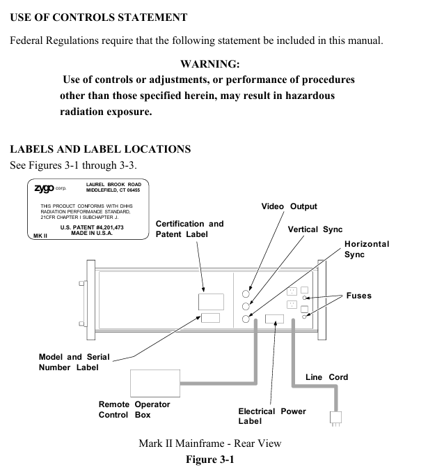
Identification location: There are certification and patent labels (US Patent No. 4201473) and model serial number labels on the back of the host; At the top (when installing the aperture converter), there is a sign that reads "Laser radiation is emitted from this aperture to avoid exposure"; After opening the lid, there are labels such as "Damaged Seal Invalid Warranty", "High Voltage Warning", "Laser Radiation When Opening, Avoid Direct Exposure" (see Figures 3-1 to 3-3).
Unpacking and installation setup
(1) Installation environment and equipment placement
Stability requirement: The host is recommended to be placed on an optical workbench (such as a granite or honeycomb air cushion platform), with a horizontal beam emitted from the right side of the equipment, making it easy to place the test piece and auxiliary components on the same platform and flexibly adapting to various testing scenarios.
Installation flexibility: In addition to the standard horizontal beam setup, the host can be installed with vertical upward/downward light output; The remote control box and movable monitor enable the host position to be optimized independently of the testing setup, suitable for laboratory prototype development, production testing, and other scenarios. It can also support multiple sets of testing setups on one host through the use of a MUX cube or mobile host.
(2) Unpacking and Inspection
System inventory: The packaging box should include the host, video monitor with bracket, lifting bracket and accessories (hardware, monitor power cord, BNC coaxial line), "Interference Pattern Interpretation and Evaluation Manual" (including mechanical parallelogram), acquisition target, "Operation and Maintenance Manual OMP-0055", "Service Manual SP-0038"; If the packaging box is damaged, please contact the shipping party immediately.
Unpacking operation: Unpacking in a clean and dry area requires two people to lift the main unit from the bottom of both ends and remove it. It is forbidden to pull or tug on the outer shell; Before removing all items, do not discard reusable packaging boxes (it is recommended to keep them for return); Cushioning materials such as foam shall be used to prevent shock during handling to avoid severe impact.
(3) Connection and switch settings
Cable connection: Connect the BNC cable according to Figure 4-1 (host monitor) and Figure 4-2 (host monitor printer); The default factory setting for the CCTV camera jumper in the host is "output synchronization", which does not require adjustment.
Power and parameters: Insert the monitor power cord into any auxiliary power outlet on the back of the host; Confirm that the position of the "75 Ω/HI-Z" switch on the monitor is correct (see Figure 4-1/4-2); The host power cord should be connected to a power source that meets the requirements of the electrical label on the back. It is recommended to use a three hole socket with neutral grounding.
Operation process
(1) Preparation before operation
Safety prerequisite: It is necessary to read Chapter 3 "Laser Radiation Safety Information" before operating the host.
Equipment preheating: After turning on, the host and monitor need to be preheated for at least 30 minutes to ensure stable performance.
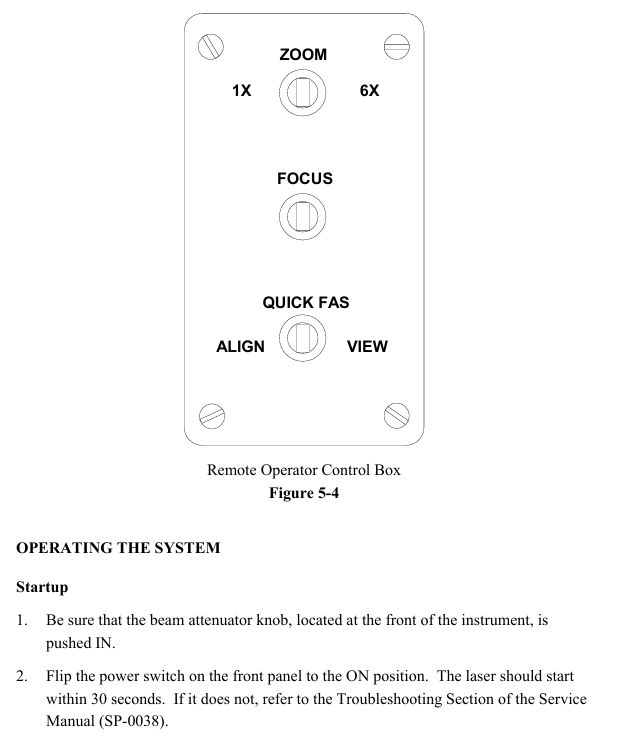
Familiarity with controls: Clearly define the functions of each button on the host and remote control box (such as the power switch, beam attenuation knob, and accessory socket tilt adjustment knob on the host; the fast stripe acquisition switch and zoom/focus adjustment switch on the remote box).
(2) Core operational steps
Boot startup
Confirm that the front beam attenuation knob of the host is pushed in, turn on the power switch, and the laser should start within 30 seconds. If it does not start, refer to the troubleshooting section of Service Manual SP-0038; There is a slow melting fuse on the back of the host (see Chapter 6 "Fuse Specifications" for the model).
Remote control box operation (see Figure 5-4)
Quick FAS switch: Center off, left dial "ALIGN" (alignment mode, hold for about 2 seconds, monitor displays aligned spot and automatic alignment crosshair), right dial "VIEW" (observation mode, hold for about 2 seconds, display interference pattern).
Zoom adjustment: With the center closed, it can achieve 6x continuous magnification (corresponding to aperture diameter for planar testing and f-number for spherical/cylindrical testing).
Focus adjustment: Center off, operate at 6x (or close to 6x) zoom, hold down the left and right keys, observe the edges of the test piece or small objects inserted into the beam (such as pen tips) until the outline is clearest (the stripes are not bent at the edges and are sharply truncated), do not directly focus on the stripes (their width is determined by the illumination intensity and needs to be adjusted by the monitor brightness/contrast).
Installation and alignment of transmission components
Universal installation: For transmissive components (flat or spherical), hold the metal edge in hand (do not touch the glass), loosen the spring clip screw of the accessory socket, insert the short metal pin of the component into the socket slot, and then rotate clockwise until it clicks into place. Finally, tighten the spring clip screw.
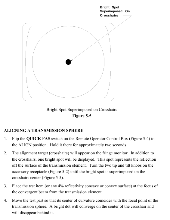
Alignment of transmission plane: After turning on the remote box, dial "ALIGN" for about 2 seconds, and the monitor will display a crosshair and two light spots (the bright spots are reflected by the uncoated surface of the transmission plane). Adjust the two tilt knobs of the accessory socket to make the bright spots coincide with the center of the crosshair.
Transmission sphere alignment: Remote box dial "ALIGN" for about 2 seconds, the monitor displays a crosshair and a light spot (reflected by the transmission element surface), adjust the tilt knob to make the light spot coincide with the center of the crosshair; Place the test piece (or 4% reflectivity concave convex surface) at the focal point of the converging beam of the transmissive element, and move the test piece so that the curvature center coincides with the focal point of the transmissive sphere (the bright spot converges at the center of the crosshair and disappears); Switch the "VIEW" mode. If the bull's-eye pattern displayed by the monitor is offset, use the X/Y knob of the 3/5 axis bracket to center (do not move the tilt knob of the host), and then focus through the Z axis knob (push the movement direction of the observation ring on the back of the bracket: move the Z axis clockwise when moving toward the center, and counterclockwise when moving outward). Finally, adjust the X/Y knob at the socket end of the transmission element to control the number of stripes to 0-7 (the best observation effect).
Installation and alignment of aperture converter
Preliminary preparation: Remove the transmission component from the accessory socket of the host, place a flat reflector with two axis brackets (reference or transmission plane) in the laser light path (about 45.7cm away from the host), and align the reflector using the "transmission plane alignment" process (this alignment state needs to be maintained).
Converter installation: Remove the transmission element from the converter, insert its short metal pin into the socket slot of the host accessory, push it in and rotate it to fix it, tighten the locking screw, align the tilt knob of the host accessory socket with the converter, and remove the flat reflector.
Component alignment: Install the transmission component on the converter, use the two tilt knobs at the aperture end of the converter (do not touch the host socket knob), and follow the "Transmission Component Alignment" process; If a transmissive sphere is installed on the converter, additional alignment checks are required: the test piece is placed at the focal point of the converging beam. In "VIEW" mode, if the target center pattern is offset, use the converter socket knob to adjust it. If the aperture is not full of the screen (vignetting), adjust it through the Zygo 3/5-axis bracket X/Y, and optimize the focusing method according to the spherical plane alignment. The final number of stripes is controlled between 0-7.
Interference pattern evaluation and geometric distortion inspection
Interference pattern evaluation: It is necessary to quantify the deviation between the test fringes and the ideal fitting pattern (usually expressed as a fraction of the ideal fringe spacing). It is recommended to refer to the "Interference Pattern Interpretation and Evaluation Manual AB-0001". Zygo provides real-time interference pattern evaluation equipment, and information can be requested as needed.
Geometric distortion inspection: Preheat the equipment for 30 minutes (the roundness change of the image during the preheating period is normal and does not need to be adjusted), remove the accessory socket transmission element, place a reference plane with two axis brackets (4% or 90% reflectivity) 12 inches away from the host, and align it with Quick FAS; Insert vertically arranged parallel thin lines (or adjustable parallelograms provided in the user manual) into the beam near the reference plane, zoom to 6x and restore to 1x, observe the monitor line pattern (which can be photographed by a video printer), and if there is non ideal distortion (such as aspect ratio deviation), refer to Service Manual SP-0038 for correction, or contact Zygo service department; If there is a ZAPP/PC system, the host signal can be directly evaluated (its circular mask should display as a perfect circle, and the host CCTV needs to be adjusted to fill the aperture image with the mask).
(3) Operation precautions
Do not touch the glass surface of optical accessories with bare hands. If touched without professional cleaning experience, do not clean it yourself (soft coating only has a reflectivity of 90% and is easily damaged); When not in use, the optical accessories should be returned to the protective box.
When installing optical accessories, avoid excessive force that may cause strain or damage to the components; When clamping attachments, do not tighten the screws too tightly to prevent deformation of the reference surface.
The accessories are lightly clamped with nylon screws on the two axis bracket. If the bracket tilts backwards, the accessories may fall off, so the bracket should not be moved or tilted when clamping the accessories.
The host needs to be used along the axis defined by the automatic alignment system, and the alignment accuracy must be ensured in the alignment mode, otherwise there may be no stripe display in the observation mode; The intensity of the two interfering beams needs to be close to obtain the best stripe contrast.
The distance between the test piece and the host should be moderate, shortening the optical path length of the last reflector and reducing the cavity length to reduce wavefront distortion caused by unstable air paths.
Maintenance and accessory management
(1) Daily maintenance
Appearance cleaning: clean the blue shell with a soft cloth dipped in a mild furniture polish, and clean the gray painted parts with a mild spray cleaner.
Component lubrication: The spring positioning pin after the socket clip of the host accessory needs to be lubricated with Lubriplate or similar lithium based bearing grease.
Optical component care: The main optical cabin is sealed, and the internal components are dust-proof; The attached optical components should be stored properly in a protective box to reduce the need for cleaning and the risk of damage; Clean only when the components are visibly dirty, prioritize cleaning the local area rather than the entire surface.
Optical cleaning process (to be strictly followed to avoid damage)
Cleaning materials (or equivalent): Orvus WA paste (KWW Warehouse Chemicals), distilled water, spectral grade methanol (Fisher Scientific A-408), spectral grade acetone (Fisher Scientific A-19), Multilith pad (Multigraphics # 200-847), lens paper (Aldine Papers 8 x 9 inches), vinyl gloves (Laminaire # 607).
Preparation: Before cleaning the special coating, check the protective instructions, remove the jewelry on your hands, thoroughly wash your hands, wear gloves, use clean filtered air to blow away loose particles on the optical surface, and check for residual pollutant types.
Specific cleaning procedures (methanol/acetone is toxic and flammable, caution is required; do not rinse the optical surface with flowing liquid to prevent damage to the seal/bonding area; consumables cannot be reused):
Loose particles on uncoated surface: Fold the lens paper into a 2-inch square pad, dip it in methanol (without dripping water), gently scratch the circular surface from the center outwards to wipe (change the pad every time), and wipe the square/rectangular surface from one end to the other.
Loose particles on the coating surface: Fold the Multilith pad in half four times, dip it in acetone (without dripping water), and wipe it according to the corresponding shape.
Semi solid pollutants on coated/uncoated surfaces: Dip the Multilith pad in Orvus solution (without dripping water) and gently wipe the contaminated area (according to the corresponding shape, do not scratch); Dip the pad in distilled water to wipe off Orvus; Dip the pad in methanol again to absorb residual moisture; Finally, change the pad and dip it in acetone, slowly wipe it in one direction and "lift it off" to finish (without dragging it to the edge), repeat until there are no traces of acetone; If there are still stains, the entire process needs to be repeated.
Special Warning: Zygo does not recommend cleaning high reflectivity soft coatings on transmission/reference components. If cleaning is necessary, the risk of damage must be borne by the user.
Maintenance of video monitor: no user serviceable parts, the shell is cleaned with a damp cloth or mild spray cleaner, and the screen is wiped with a commercial glass cleaner or a special cleaner for computer screen, and the fault needs to be sent back to Zygo for maintenance.
Laser head replacement: The laser head can be used normally for many years without any faults. If the output power is too low or the vibration stops, please refer to the "Service Manual SP-0038" for replacement and use Zygo original accessories.
(2) Accessories Management
Recommended spare parts list (Table 6-1): Classified by replacement probability (Class A: May need to be replaced, Class B: Less need to be replaced but recommended for backup to reduce downtime, Class C: Very rarely need to be replaced, optional backup), including laser, CCTV camera, diffuser assembly, motor drive PCB, laser power supply, beam splitter spatial filter, etc., with part numbers, descriptions, and quantities listed.
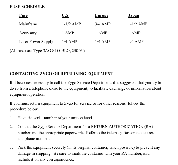
Fuse specifications (Table 6-2): All are 250V 3AG slow melting fuses, with main units of 1.5A in the United States, 0.75A in Europe, and 1.5A in Japan; accessories: Global 1A; laser power supply: Global 0.25A.
- OMRON
- ABB
- General Electric
- EMERSON
- Honeywell
- HIMA
- ALSTOM
- Rolls-Royce
- MOTOROLA
- Rockwell
- Siemens
- Woodward
- YOKOGAWA
- FOXBORO
- KOLLMORGEN
- MOOG
- KB
- YAMAHA
- BENDER
- TEKTRONIX
- Westinghouse
- AMAT
- AB
- XYCOM
- Yaskawa
- B&R
- Schneider
- KONGSBERG
- NI
- WATLOW
- ProSoft
- SEW
- ADVANCED
- Reliance
- TRICONEX
- METSO
- MAN
- Advantest
- STUDER
- DANAHER MOTION
- Bently
- Galil
- EATON
- MOLEX
- DEIF
- B&W
- ZYGO
- Aerotech
- DANFOSS
- Beijer
- Moxa
- Rexroth
- Johnson
- WAGO
- TOSHIBA
- BMCM
- SMC
- HITACHI
- HIRSCHMANN
- Application field
- XP POWER
- CTI
- TRICON
- STOBER
- Thinklogical
- Horner Automation
- Meggitt
- Fanuc
- Baldor
- SHINKAWA
- Other Brands
- UniOP
- KUKA
- Iba
- Beckhoff
-
 Basler D90 96801 100 PCB Card
 -
 Basler XR2002F Voltage Regulator (110 VAC, 48-480 Hz)
 -
 Basler SR8A-2B14B3A Regulator
 -
 Basler 9561500100 Module
 -
 Basler DECS-400 BE1-11 System
 -
 Basler DECS-100-B15 Excitation Control
 -
 Basler SCP 210 Frequency Controller
 -
 Basler SR4A-2B15B3A Static Voltage Regulator
 -
 Basler BE1-32R Power Relay
 -
 Basler PIA2400-17GM Power Interface Adapter
 -
 Basler MVC 232 Manual Voltage Control Module
 -
 Basler SSR 32-12 Static Voltage Regulator
 -
 Basler 5MW AVR Generator Voltage Regulator
 -
 Basler VR63-4B Voltage Regulator
 -
 Basler DECS-100-A05 AVR for Engine Generator
 -
 Basler DECS-100-B15 Automatic Voltage Regulator
 -
 Basler BE1-32R Directional Power Relay
 -
 Basler BE1-87B Differential Relay
 -
 Basler UFOV 260A Protective Module
 -
 Basler 9-2614-02-100 PCB Rev M
 -
Basler DECS-100-B15 Digital AVR
-
 Basler 9284900103 PS DECS-400N
 -
 Basler D4N3H1U Intertie Protection
 -
 Basler DECS-100-B15 A15 AVR
 -
 Basler KR4F Voltage Regulator
 -
 Basler BE26434 T14 Transformer
 -
 Basler SR8A-2B15B3A Regulator
 -
 Westinghouse 774B472A12 AR Relay
 -
Basler DECS-100-B15 AVR
-
Basler XR2002F Regulator 110V
-
Basler SR125-E Static Regulator
-
 Basler SSR 125-12 Regulator
 -
 Basler MOC2599 Motor Pot
 -
 Basler BE1-DFPR Feeder Relay
 -
 Basler CBS 305 Current Boost
 -
 Basler BE1-25 AutoSync
 -
 Basler MVC 300 Voltage Control
 -
 Basler BE3-25A AutoSync
 -
 Basler KR7FF Static Regulator
 -
 Basler 90-49000-100 Regulator
 -
 Basler 880 kVA Dry Type Transformer Specs
 -
 Basler Electric BE1-25 Sync-Check Relay Specs
 -
 Basler SSR 125-12 Voltage Regulator Specs
 -
 Basler Electric BE1-851 Overcurrent Relay Review
 -
Basler Electric 149D930G02 Control Sub-Assembly
-
 Basler Electric BE1-81O/UT Frequency Relay Specs
 -
 Basler Electric BE1-51/27C Overcurrent Relay
 -
 Basler Electric 149D956G02 Industrial Component
 -
Basler Electric BE1-51A Overcurrent Relay Specs
-
 Basler Electric BE1-40Q Loss of Excitation Relay
 -
 Basler DECS-200 Excitation Control System
 -
 Basler DECS-200 Voltage Regulator 56-277V AC / 125V DC
 -
Basler BE1-87T Transformer Differential Relay
-
 Basler RDP-110-S1 Protection Relay
 -
 Basler BE1-700V Digital Protective Relay
 -
 Basler BE1-951 Overcurrent Protection System
 -
 Basler DECS-300 Digital Excitation Control
 -
 Basler DECS-200 Digital Excitation Control
 -
 Basler DECS-200-1C Excitation Control System
 -
Basler DECS-200-1L Digital Excitation Control
-
 Basler Electric BE1-GPS Generator Protection System
 -
Basler Electric DECS-200-1C Digital Excitation Controller
-
 Basler Electric DECS125-15 Excitation Control with Power Module
 -
 Basler Electric BE1-87G Differential Relay
 -
 Basler Electric BE1-11 Protection System I5A3M2P2N0EA00
 -
Basler Electric DECS-200-1C Excitation Control System
-
Basler Electric BE1-11g Generator Protection Relay
-
Basler Electric DECS 125-15-B2C1 V2.0.9 Excitation Control
-
 Basler Electric BE1-81O/UT3ED1JA7N2F Frequency Relay
 -
Basler Electric BE1-81O/UT3EE1YB7N1F Frequency Relay
-
 Basler Electric DECS-200-1L Digital Excitation Control System
 -
Basler DECS125-15-B2C1 Excitation Control
-
 Basler 9507900205 SSR Retrofit Voltage Regulator
 -
 Basler BE2000E Digital Voltage Regulator
 -
 Basler BE1-GPS Generator Protection System
 -
Basler DECS-250-CN1CN1N Digital Excitation Control
-
 Basler DGC-2020 Genset Controller
 -
 Basler BE1-81O UT3ED1LA7N0F Frequency Relay (Variant)
 -
 Basler BE1-81O UT3EE1YA9S0F Frequency Relay (Variant)
 -
Basler BE1-81O Over/Under Frequency Relay
-
Basler DECS125-15 Digital Excitation Control
-
Basler Electric BE1-951 Overcurrent Protection System
-
 Basler Electric BE1-700V Digital Protective Relay
 -
 Basler Electric APR63-5 Automatic Voltage Regulator
 -
Basler Electric BE1-851 Overcurrent Protection System
-
Basler Electric DECS-250-LN1SN1N Excitation Control
-
 Basler Electric BE1-87T Transformer Differential Relay
 -
Basler Electric DECS-200-1L Excitation Control System
-
 Basler Electric 9310300100 DECS-300 Excitation Control
 -
 Basler Electric SSE-N 125-4.5KW Shunt Exciter Regulator
 -
 Basler Electric DGC-2020HD-5NS1DNSBA Genset Controller
 -
Basler Electric BE1-81-O/UT3EE1JB7N1F Frequency Relay
-
Basler Electric BE1-81T1EE1WA0N1F Frequency Relay
-
 Basler Electric BE1-25M1EA6PN5R1F Sync-Check Relay
 -
 Basler Electric BE1-GPS Generator Protection System
 -
Basler Electric DECS-250-LN1SN1N Excitation Control Rev V
-
 Basler Electric DECS-250-CN2CN1N Excitation Control
 -
Basler Electric BE1-50/51B-207 Overcurrent Relay
-
Basler Electric DECS-300-C0N0 Excitation Control System
-
Basler Electric DECS-200 Digital Excitation Control System
-
Basler Electric DECS-250-LN1CN1N Excitation Unit
-
Basler Electric DECS-250 LN2SA1D Excitation Unit Specs
-
Basler Electric BE1-87T Transformer Relay Review
-
Basler Electric BE1-11 Protection System
-
Basler Electric BE1-GPS100-E4N1H1N Protection System
-
 Allen-Bradley 442G-MABH-R Safety Module
 -
 Beckhoff CX1030-0111 PLC Assembly Profile
 -
 FANUC IC693CPU364 PLC Module
 -
 Orange Denmark Type 200816 220 PLC Specs
 -
 OMRON C200H-SNT31 Sysmac PLC Module
 -
 Allen Bradley 20AB022A3AYNANC0 PowerFlex 70
 -
 OMRON C200HW-PCU01 Position Control Unit
 -
 ABB AO845A-eA Analog Output Module
 -
 OMRON CJ1M-CPU22 CPU Unit
 -
 Allen Bradley 100-E265ED11 Contactor
 -
 Honeywell 51304511-100 Interface Module
 -
 SOLEXY BXF3S0101N0018 Gateway Module
 -
 OMRON CJ2H-CPU65 CPU Unit
 -
 Automation Direct GS2-45P0 AC Drive
 -
 M68-2000 2-Axis Motion CNC Controller
 -
 OMRON CJ1M-CPU11 V3.0 PLC CPU Unit
 -
 OMRON CJ1W-NC413 4-Axis Positioning Controller
 -
 OMRON 3G2A3-PRO16 Programming Console HMI
 -
 Siemens 3VT8440-2AA04-2GA2 Molded Case Circuit Breaker
 -
 Siemens 3RT5045 Contactor Series
 -
 OMRON C200HS-CPU01-E SYSMAC PLC Controller
 -
 OMRON C500-NC103-E Positioning Control Unit
 -
 OMRON CJ1W-TC001 Temperature Control Unit


