
How to unpack and install the Zygo Mark II 4-inch interferometer system?
Video monitor: Display real-time interference patterns collected by the host, 9-inch diagonal screen, equipped with a universal bracket, can be placed on the desktop or installed above the host through a dedicated lifting bracket, supporting flexible adjustment of viewing angle to optimize observation effect.
Optional VP-2 video printer: uses specially coated paper to provide hard copy recording of interference fringe patterns for easy archiving and analysis.
How to unpack and install the Zygo Mark II 4-inch interferometer system?
System composition and technical parameters
(1) System core module
Mark II host: The core function is to collect real-time interference patterns, including a 632.8nm circularly polarized output HeNe laser (replaceable on site), laser power supply, beam splitter spatial filter (BDSF), CCTV camera, and a sealed optical cabin to protect precision optical components. It is equipped with accessory sockets (for installing transmission components) and a remote control box (connected by cables).
Video monitor: Display real-time interference patterns collected by the host, 9-inch diagonal screen, equipped with a universal bracket, can be placed on the desktop or installed above the host through a dedicated lifting bracket, supporting flexible adjustment of viewing angle to optimize observation effect.
Optional VP-2 video printer: uses specially coated paper to provide hard copy recording of interference fringe patterns for easy archiving and analysis.
(2) Key technical parameters
Specific parameters of the module
Mark II host aperture: 4-inch diameter, capable of continuous zoom up to 2/3 inch (6x zoom range); Alignment: Automatic alignment and fast stripe acquisition system; Video output: 520 lines/60Hz (EIA RS170 standard) or 625 lines/50Hz (CCIR standard), 2:1 interlaced scanning, BNC interface, synchronous signal including horizontal and vertical; Dimensions: 648mm x 533mm x 203mm (length x width x height); Weight: 34kg; Power supply: 115 ± 10VAC/60Hz, 110 ± 10VAC/50Hz, or 230 ± 10VAC/50Hz, 50W without monitor, 85W with monitor (single-phase)
Video monitor screen: 9-inch diagonal; Interface: BNC type; Synchronization: Built in; Video input: Supports 75 Ω or high impedance terminals; Power supply: 115 ± 10VAC/60Hz, 300mA; Dimensions: 311mm x 229mm x 241mm (length x width x height); Weight: 6.35kg
Laser Radiation Safety Regulations
Laser characteristics and risk warning: The host emits visible red light, with no harmful invisible radiation. The radiation power is less than 1 milliwatt (1/1000 watt), the wavelength is 632.8nm, and the irradiation time exceeds 0.25 seconds. It cannot burn or drill holes, but it is necessary to avoid direct viewing of the beam and strong light reflection to prevent eye damage. Skin contact is not harmful.
Classification and compliance standards: Complies with ANSI Z136.1-1980 standard and belongs to "low-power Class II laser"; Comply with the regulations of the National Center for Devices and Radiological Health (NCDRH) under the US Food and Drug Administration (FDA) effective August 2, 1976 (for laser products manufactured after August 1, 1976), and meet the DHHS radiation performance standards (21CFR Chapter 1, Subcapter J).
Safe operation and identification
Control usage: Only operate control buttons, adjust parameters, or execute procedures as specified in the manual. Violation may result in hazardous radiation exposure.
Key components: The front panel of the host has a green radiation emission indicator light (which lights up when turned on and indicates Class II radiation), and a "BEAM ATTEN." beam attenuation knob (pull out to turn off the laser, push in to turn on); The laser head and power supply need to use Zygo original accessories, and replacement should follow the process outlined in Service Manual SP-0038 to ensure compliance with federal radiation standards.
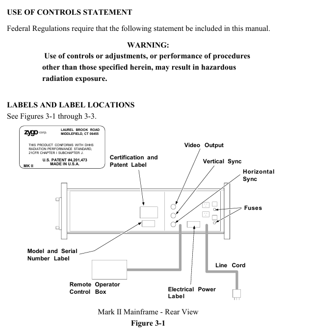
Identification location: There are certification and patent labels (US Patent No. 4201473) and model serial number labels on the back of the host; At the top (when installing the aperture converter), there is a sign that reads "Laser radiation is emitted from this aperture to avoid exposure"; After opening the lid, there are labels such as "Damaged Seal Invalid Warranty", "High Voltage Warning", "Laser Radiation When Opening, Avoid Direct Exposure" (see Figures 3-1 to 3-3).
Unpacking and installation setup
(1) Installation environment and equipment placement
Stability requirement: The host is recommended to be placed on an optical workbench (such as a granite or honeycomb air cushion platform), with a horizontal beam emitted from the right side of the equipment, making it easy to place the test piece and auxiliary components on the same platform and flexibly adapting to various testing scenarios.
Installation flexibility: In addition to the standard horizontal beam setup, the host can be installed with vertical upward/downward light output; The remote control box and movable monitor enable the host position to be optimized independently of the testing setup, suitable for laboratory prototype development, production testing, and other scenarios. It can also support multiple sets of testing setups on one host through the use of a MUX cube or mobile host.
(2) Unpacking and Inspection
System inventory: The packaging box should include the host, video monitor with bracket, lifting bracket and accessories (hardware, monitor power cord, BNC coaxial line), "Interference Pattern Interpretation and Evaluation Manual" (including mechanical parallelogram), acquisition target, "Operation and Maintenance Manual OMP-0055", "Service Manual SP-0038"; If the packaging box is damaged, please contact the shipping party immediately.
- OMRON
- ABB
- General Electric
- EMERSON
- Honeywell
- HIMA
- ALSTOM
- Rolls-Royce
- MOTOROLA
- Rockwell
- Siemens
- Woodward
- YOKOGAWA
- FOXBORO
- KOLLMORGEN
- MOOG
- KB
- YAMAHA
- BENDER
- TEKTRONIX
- Westinghouse
- AMAT
- AB
- XYCOM
- Yaskawa
- B&R
- Schneider
- KONGSBERG
- NI
- WATLOW
- ProSoft
- SEW
- ADVANCED
- Reliance
- TRICONEX
- METSO
- MAN
- Advantest
- STUDER
- DANAHER MOTION
- Bently
- Galil
- EATON
- MOLEX
- DEIF
- B&W
- ZYGO
- Aerotech
- DANFOSS
- Beijer
- Moxa
- Rexroth
- Johnson
- WAGO
- TOSHIBA
- BMCM
- SMC
- HITACHI
- HIRSCHMANN
- Application field
- XP POWER
- CTI
- TRICON
- STOBER
- Thinklogical
- Horner Automation
- Meggitt
- Fanuc
- Baldor
- SHINKAWA
- Other Brands
- UniOP
- KUKA
- Iba
- Beckhoff
- ADLINK
-
 Sigmatek MDD111-1 DIAS Drive Axis Module
 -
 Sigmatek DKL042 05-024-042 Terminal Module
 -
 Sigmatek DM822 Control Module
 -
 Sigmatek CDM167 12-008-167-O Module
 -
 Sigmatek TAE151 Touch Display Unit
 -
 Sigmatek DCC041 SLIDES Module 05-700-041-D
 -
 Sigmatek AKM65M-ANC2GBB0 PM Servo Motor
 -
 Sigmatek ETT221 01-230-221 Operator Terminal
 -
 Sigmatek SLIDES DAM 124 Analog Module
 -
Sigmatek AKM31C-ANCNGBB0 Servo Motor
-
 Mannesmann Demag Sigmatek CP626 Central Unit
 -
 SIGMATEK 0332.554.03 Board 371071000154
 -
 SIGMATEK 12-250-021 Base Plate Back Panel CM5V020
 -
 SIGMATEK DM162 S-DIAS Digital Mix Module
 -
 DEMAG ERGOTECH 061 381 66 Sigmatek 9842.243.02 Circuit Board
 -
 SIGMATEK CP313-1 PLC Module
 -
Sigmatek ETV0551-2 VARAN Touch Terminal
-
 Sigmatek SDM 081 FS S-Dias Safety Module
 -
 DEMAG 05-250-023 Ergotech Motherboard with Sigmatek TMS012
 -
Sigmatek CM5V020 12-250-023-K Wiring Base
-
 Sigma Tek 5000B-37 Attitude Gyro Indicator
 -
 Sigmatek SDD120-2 DIAS Drive
 -
 Sigmatek CME221 Memory Module
 -
 Sigmatek DCP640 DIAS Central Unit
 -
 Sigmatek STO040 Safety Output Module
 -
Sigmatek CET281 Control Panel
-
 Sigmatek CIPC LX800 Demag NC5 CPU
 -
 Sigmatek DKL093 05-024-093 Terminal Module
 -
 Sigmatek AI088 20-009-088 Analog Input Module
 -
Sigmatek CAI888 Analog Input Module
-
SIGMATEK CCA021 12-025-021 Analog Output Module
-
SIGMATEK 1104.579.05 Control Module
-
SIGMATEK SDI100 Digital Input Module
-
 SIGMATEK C-IPC 256MB LX800 Compact Dias
 -
 SIGMATEK 9423.090.02 Control Module
 -
SIGMATEK C-IPC 256 Power Supply 148498
-
 SIGMATEK CAI025 Analog Input Module
 -
 SIGMATEK CTO166 Digital Output Module
 -
 SIGMATEK CP112 20-004-112 Processor Module
 -
SIGMATEK CAI887 12-009-887 Safety Module
-
 Sigma-Tek 4000B-31 Directional Gyro 1U262-002-42
 -
Sigmatek C-IPC 256MB LX800 IPC Controller
-
Sigmatek C-IPC 01-450-031 Industrial PC LX800
-
Sigmatek C-IPC 256 Industrial PC Controller
-
Sigmatek CCP-531 PLC Processor Module
-
Sigmatek CDI163 Digital Input Module
-
 Sigmatek ETV0501 VARAN Terminal 12-230-0501
 -
 Sigmatek CTMS020 C-DIAS Technology Module
 -
 Sigmatek CIV512 VARAN Switch Module
 -
 Sigmatek HU011 20-080-011 Interface Module
 -
SIGMATEK SLIDES DAM 124 Module
-
 SIGMATEK C-IPC 161 01-450-161L Industrial PC
 -
SIGMATEK C-IPC 128MB VIA 733MHz 01-450-024-K
-
 SIGMATEK 12-780-012 R8-IPC Geode LX800 Module
 -
SIGMATEK CAM124 Analog Module
-
 SIGMATEK S1 032-8AF61-R4 EZ Servo Motor
 -
 SIGMATEK CTO163 Digital Output Module
 -
 SIGMATEK CCP082 12-004-082 Processor Module
 -
 SIGMATEK CRCH081 C-DIAS Temperature Module
 -
 SIGMATEK PC322-K 01-310-322-K Industrial PC
 -
SIGMATEK SDD310-2 Servo Drive
-
 SIGMATEK AI084 Analog Input Module
 -
SIGMATEK CRCH081 12-752-081 Temperature Module
-
Sigma-Tek 5000L-4 Attitude Gyro 1U284-001-3
-
 SIGMATEK CM5V020 12-250-023-K Wiring Module
 -
Sigma-Tek 4000H-6 Directional Gyro IU262-035-7
-
 SIGMATEK Dias DCP160 05-004-160 Processor Module
 -
SIGMATEK 0147.395.02 Control Module
-
SIGMATEK A1084 Control Module
-
SIGMATEK DI200 20-006-2000 Digital Input Module
-
Sigmatek DNC115 Encoder Module
-
 Sigmatek DAM122 05-017-122 Analog Module
 -
Sigmatek 9802.289.01 Control Board TA71 Display
-
Sigmatek TO127 20-007-127 Digital Output Module
-
Sigmatek DNC031 05-011-031 Digital Module
-
Sigmatek VI022 20-003-022 Interface Module
-
Sigmatek CAI085 Analog Input Module
-
 Sigmatek CP111 S-DIAS CPU Module
 -
Sigmatek CTMS030 Krauss Maffei Module
-
 Sigmatek CAM123 Control Module
 -
 Sigmatek TAE732-P 01-240-732-P Touch Display Unit
 -
Sigmatek MDM021 Digital Mixed Module
-
Sigmatek DCP642 DIAS Central Unit
-
 Sigmatek CST022 12-014-022 C-DIAS Module
 -
 Sigmatek SRO021 20-893-021 Safety Relay Output
 -
 Krauss Maffei MC5 Control System Sigmatek
 -
 Sigmatek DC061 Module 18-24VDC 300mA
 -
 Herrmann EVT0855 Ultrasonic Welder Touch Panel
 -
Sigmatek CIV521 Control Module 1.4A 2W
-
Sigmatek DDI61 05-006-161 Digital Input Module
-
SIGMATEK ETT312-E Touch Terminal 01-230-312
-
Cessna S3326-1 Sigma Tek 5000B-67 Gyro 1U149-015-9
-
SIGMATEK PS101 Power Supply Module
-
SIGMATEK 0332.554.03 Control Module 371071000154
-
 SIGMATEK ETT312-E Touch Terminal 01-230-312
 -
SIGMATEK CDM163 Control Module
-
 SIGMATEK VSV046 16-023-046 Module
 -
SIGMATEK AM221 20-017-221 Analog Module
-
SIGMATEK CTS051 12-053-051 Control Module
-
SIGMATEK AM221 20-017-221 Analog Module
-
Sigmatek CSDI161 12-891-161 Safety Input Module
-
Sigma Tek 4000C-1 Directional Gyro Indicator
-
Sigmatek ETV0501 12-230-0501 VARAN Terminal
-
Sigmatek DDM165 SLIDES Module
-
Sigmatek N100 20-011-100 Control Module
-
Sigmatek AKM54K-ANC2R-B0 PM Servo Motor
-
Sigmatek CTO166 Digital Output Module
-
Sigmatek CP212-K 20-004-212-K CPU Module
-
Sigmatek CDI161 Digital Input Module
-
Sigmatek DCC080 05-700-080-2 Control Module
-
 SIGMATEK SCP011 S-DIAS Safety CPU
 -
SIGMATEK SCP011 S-DIAS Safety CPU
-
SIGMATEK SRO022 Relay Output Module
-
SIGMATEK MDD 121 Drive Axis Module
-
SIGMATEK DSI021 SLIDES Siemens Interface
-
SIGMATEK DIAS DCP161 Module 05-004-161
-
 Sigmatek ETT312 Built-in Touch Terminal
 -
SIGMATEK DCP 643 DIAS Controller System
-
SIGMATEK CIO021 Multi I/O Module
-
SIGMATEK CTMS020 Control Module
-
 Sigmatek CME 221 Memory Module
 -
Sigmatek 0420.615.01 Control Board
-
Sigmatek CP111 20-004-111 CPU Module
-
Sigmatek 9405.065.03 Control Board
-
Sigmatek ETEK 01-450-032-K C-IPC 256MB Industrial PC
-
Sigmatek CTO163 12-007-163 Safety Output Module
-
Sigmatek TO081 20-007-081 Digital Output Module
-
 Sigmatek SI021 20-022-021 Safety Input Module


