
How to install the Rockwell Automation 1757-SRM (B-series) module?
How to install the Rockwell Automation 1757-SRM (B-series) module?
Basic Information
The installation instructions for the redundant modules of the Rockwell Automation 1757-SRM series B-type ProcessLogix and ControlLogix systems are designed to guide users in installing the redundant module into the ProcessLogix or ControlLogix redundant chassis, covering the entire process of installation preparation, operation steps, fault handling, technical specifications, and more.
Important User Information and Security Standards
(1) Definition of Core Security Warning
The document specifies the meanings of different security signs to avoid operational risks, as follows:
Meaning of identification
Warning: Operating scenarios in hazardous environments that may cause explosions, resulting in personal injury, property damage, or economic loss
IMPORTANT annotation is crucial for the successful application and understanding of product information
Attention: Identify operational methods that may result in personal injury, property damage, or economic loss, and explain how to identify and avoid hazards and consequences
Labels on or inside SHOCK HAZARD equipment (such as drivers, motors) warning of hazardous voltage
Labels on or inside BURN HAZARD equipment (such as drives, motors) warning that the surface may reach dangerous temperatures
(2) Special environmental usage requirements
North American Hazardous Area Certification: Products marked as "CL I, DIV 2, GP A, B, C, D" are only applicable to Class I, Division 2, Groups A, B, C, D hazardous areas and non hazardous areas; When the system is used in combination, the overall temperature level must be determined by the temperature code with the lowest "T" number, and the equipment combination must be inspected by the local competent department.
European Hazardous Place Certification: Products marked with EEx comply with EU Directive 94/9/EC, are suitable for potentially explosive environments, must be installed in enclosures that meet at least IP54 protection level (Class I, Zone 2 environment), and can only be used in conjunction with ATEX certified backplates; At the same time, the device is not resistant to sunlight and other ultraviolet radiation, and transient interference should be prevented from exceeding the rated voltage by more than 40% in Class I Zone 2 environment.
General environmental requirements: Suitable for industrial environments with pollution level 2, overvoltage category II applications (compliant with IEC 60664-1), with no need for derating at altitudes up to 2000 meters (6561 feet); Belonging to Group A industrial equipment under the IEC/CISPR 11 standard, if appropriate protective measures are not taken, conducted and radiated interference may affect electromagnetic compatibility; The device is of an open design and needs to be installed in an enclosure that meets specific environmental requirements. The enclosure must have flame retardancy (non-metallic enclosures must reach 5VA, V2, V1, V0 or equivalent flame retardant levels), and the interior must be accessible with tools.
Module basic information and installation preparation
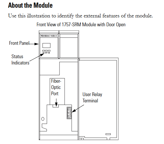
(1) Module core functions and appearance
Functional positioning: The 1757-SRM (B series) module is used for redundant control of ProcessLogix and ControlLogix systems, achieving communication and status synchronization between the primary and backup chassis through fiber optic connections, ensuring smooth switching in case of system failures.
Appearance structure: The front includes status indicator lights, fiber optic ports, and user relay terminals. These components are required to achieve module status monitoring, fiber optic connections, and external device control (such as relay linkage).
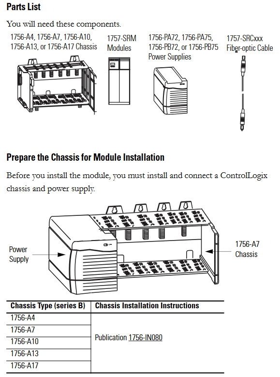
(2) Preparation before installation
Component List: Prepare 1756-A4/A7/A10/A13/A17 series chassis, 1757-SRM module, 1756-PA72/PA75/PB72/PB75 series power supply, and 1757-SRCxxx series fiber optic cable.
Static electricity protection: The module is sensitive to static electricity. Before operation, it is necessary to touch a grounded object to release static electricity and wear a certified grounding wristband to avoid touching the connectors/pins and internal circuit components of the component board. When idle, it should be stored in anti-static packaging and an anti-static workstation should be used when conditions permit.
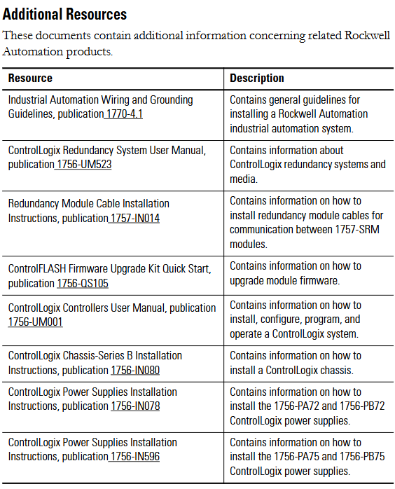
Chassis and power pre-processing: The ControlLogix chassis and power supply need to be installed and connected first. Different models of chassis (such as 1756-A4/A7, etc.) and power supplies (such as 1756-PA72/C, 1756-PB72/B, etc.) should refer to the corresponding installation instructions (such as 1756-IN080, 1756-IN078, etc.).
Module slot selection: The recommended slot positions for different models of chassis are different. For example, slot 1 or 2 is recommended for the 1756-A4 chassis, and slot 4 or 5 is recommended for the 1756-A7 chassis. It is necessary to strictly install according to the recommended positions to ensure normal communication and redundancy functions.
Redundant system assembly steps
(1) Core installation process
Fiber optic cable connection: Before installing the module, connect one end of the 1757-SRCxxx series fiber optic cable (available in 1m, 3m, 10m, 50m, 100m specifications) to the fiber optic port of the module; If the distance between the main and backup chassis exceeds 100 meters, customized fiber optic cables must be used. The optical loss at a wavelength of 1300nm should be ≤ 7dB, and the length should be ≤ 4 kilometers (2.49 miles). 62.5/125 micron multimode fiber optic cables and professionally installed SC connectors should be used.
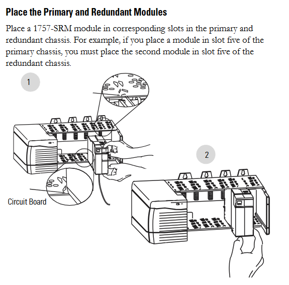
Module installation: Install the 1757-SRM module into the corresponding slots on the main and backup chassis (if the main chassis is plugged into slot 5, the backup chassis also needs to be plugged into slot 5); During installation, align the upper and lower rails of the chassis, slide the module in and ensure that the backplane connector is properly connected. When the module is aligned with other installed modules, it indicates that it is installed in place; When disassembling, press the locking clips on the upper right and lower left corners of the module, and then slide the module out.
Relay terminal wiring: If using a user relay, the wire needs to be threaded through the Steward 28A2029-0A0 model ferrite core (the core should be as close as possible to the end of the wire insulation layer), then connected to a detachable terminal block, and finally inserted into the relay terminal; The relay terminals must obtain external DC power from the same line as the SRM chassis power supply and comply with UL Class 2 (North America) or CE SELV/PELV (Europe) standards.
(2) Key operations of system configuration
Firmware upgrade: Data backup is required before upgrading (upgrading will overwrite old data), from the Rockwell Automation support website( http://support.rockwellautomation.com )Download the latest firmware and ControlFLASH firmware upgrade tool; Only supply power to one redundant chassis, wait for the module to display "FACT BOOT FLSH UPDT REQ", start the upgrade tool to complete firmware installation, and after success, the module displays "PRIM"; Repeat the operation to upgrade another chassis module. If the upgrade is interrupted, the module will display "FACT BOOT FLSH UPDT REQ" or "USER BOOT FLSH UPDT REQ" after restarting the chassis, and a new upgrade is required.
Main chassis specification and system verification:
Main chassis designation: The chassis that is powered on first automatically becomes the main chassis, the module displays "PRIM" and the PRI indicator light turns green, and the normally open contacts of the relay are closed; If both chassis are powered on simultaneously, the chassis containing the module with the smaller serial number becomes the main chassis; The initial display of the backup chassis is "DISQ" or "SYNC", the PRI indicator light is not on, and the normally open contact of the relay is disconnected.
System verification: After the main and backup chassis are powered on, automatic verification begins to verify the hardware and firmware compatibility of the main and backup modules. If the backup chassis displays "SYNC", it indicates compatibility between configuration and firmware; If "DISQ" is displayed, it may be due to mismatched chassis configuration, inconsistent firmware versions, different Keeper parameters of ControlNet module, or MAC address not set to the same node address. The problem needs to be investigated and resolved.

Module status monitoring and fault handling
(1) Status indicator lights and display interpretation
Module status display (four characters):
When starting, displaying "Txxx" (xxx is the hexadecimal test number) indicates self-test;
"Indicates a transitional state;
DISQ "indicates that the backup chassis has not passed validation," SYNC "indicates that the backup chassis has passed validation, and" PRIM "indicates the main chassis;
BOOT, ERAS, and PROG respectively represent boot mode (waiting for instructions), boot mode (erasing firmware), and boot mode (loading new firmware);
'Exxx' (xxx is an error/fault code) indicates a major malfunction and will alternately display fault information and error codes.
Health status indicator light:
Extinguished: The module is not powered on;
Always red: module self checks during startup or serious malfunction occurs;
Flashing red: The module is updating NVS, experiencing non critical faults, or configuring incorrectly;
Evergreen: The module is running normally;
Flashing green: The module is running normally but not communicating with other modules.
Inter module communication indicator light:
Extinguish: The module is not powered on or has no communication activity;
Red flash (<1 second): The module has been started and partner communication has been established;
Frequent red: serious communication failure occurs;
Green flash: There is communication activity (sampled every 250 milliseconds).
Chassis status indicator light:
Extinguish: The module is not powered on or the chassis is in standby/fault state;
Green flash (<1 second): Power on, partner module is determining the main state;
Evergreen: The chassis is in the main engine state.

(2) Fault type and handling
Fault classification:
Minor recoverable faults: do not affect redundant operations, modules may clear on their own;
Minor unrecoverable fault: does not affect redundant operations, but has no recovery mechanism;
Serious recoverable faults: affecting redundant operations (possibly not immediate), such as backup module failures that may affect control in the event of a host failure;
Serious unrecoverable fault: fatal fault, redundant operation stopped, possible switching, module replacement required.
Common faults and solutions:
|Fault code/display | Fault description | Handling measures|
|CFG LOG ERR | Configuration log error | No action required|
|COMM RSRC ERR | Communication resource error | Reset 1757-SRM module|
|COMM ERR PRT2 | Port 2 communication error (inter module link) | Check or replace 1757-SRCxxx fiber optic cable|
|FLSH UPDT REQ | Flash update required | Use corresponding firmware version to upgrade module|
|HDW ERR | Hardware Failure | Replace 1757-SRM Module|
|WDOG FAIL | Watchdog task status check failed | Replace 1757-SRM module|
Recovery instruction: The module displays "RPLC MOD" and needs to be replaced, "RSET MOD" needs to be reset, "REMV MOD" needs to be removed, and "SEAT MOD" needs to be reinserted.
Technical specifications
(1) Module core parameters
Category parameter values
Backplane current 3.3V DC 0.75A
5.1V dc 1.0A
24V dc 0.160A
Dimensions (height x width x depth) Standard ControlLogix chassis (2 slots wide) 14.5 x 7 x 14 centimeters (5.71 x 2.76 x 5.51 inches)
Weight - Approximately 0.452 kilograms (14.53 ounces)
Shell Protection Level - None (Open)
Temperature code IEC T4
North American T4A
Maximum power consumption -11.28W
Maximum heat dissipation -38.49 BTU/hour
Isolation voltage relay terminal to system for a continuous 30V, basic insulation type (853V AC test for 60 seconds)
(2) Redundant cable parameters
Parameter values
Connector SC type (fiber optic)
Cable type 62.5/125 micron multimode fiber
1 channel (sending and receiving fiber optic)
Wavelength 1300nm
(3) User relay terminal parameters
Parameter values
Power requirement: 11-30V DC; Typical current of 270mA at 24V DC (must comply with UL Class 2 or CE SELV/PELV standards)
Guiding load rated 30V DC Class 2/SELV, 100mA
Wiring category (Port 1) 3
Suitable for solid or stranded shielded copper wires of 0.3-2.1 square millimeters (22-14 AWG), rated temperature ≥ 75 ℃ (167 ℉), with a maximum insulation layer of 1.2 millimeters (3/64 inches)
Terminal block torque 0.6-0.8 Nm (5-7 pounds inches)
(4) Environmental specifications
Parameter values
Working temperature 0-60 ℃ (32-140 ℉) (compliant with IEC 60068-2-1, 60068-2-2, 60068-2-14 standards)
Storage temperature -40-85 ℃ (-40-185 ℉) (compliant with IEC 60068-2-1, 60068-2-2, 60068-2-14 standards)
Relative humidity 5% -95% (non condensing) (in accordance with IEC 60068-2-30 standard)
Vibration (working) 2g @ 10-500Hz (compliant with IEC 60068-2-6 standard)
50g impact (non working) (compliant with IEC 60068-2-27 standard)
Impact (working) 30g (compliant with IEC 60068-2-27 standard)
Radiation emission complies with CISPR 11:1 Group A
Electrostatic immunity: 6kV for contact discharge and 8kV for air discharge (in accordance with IEC 61000-4-2 standard)
(5) Certification qualifications
The module is approved by UL (Industrial Control Equipment, document E65584) and CSA (Process Control Equipment, document LR54689C); Multiple certifications such as LR69960C, FM, CE (compliant with the 2004/108/EC EMC Directive), C-Tick (compliant with the Australian Radio Communications Act), EEx (compliant with the 94/9/EC ATEX Directive), T Ü V (functional safety certification, up to SIL 2), etc. are applicable to compliance requirements in different regions and scenarios.
- OMRON
- ABB
- General Electric
- EMERSON
- Honeywell
- HIMA
- ALSTOM
- Rolls-Royce
- MOTOROLA
- Rockwell
- Siemens
- Woodward
- YOKOGAWA
- FOXBORO
- KOLLMORGEN
- MOOG
- KB
- YAMAHA
- BENDER
- TEKTRONIX
- Westinghouse
- AMAT
- AB
- XYCOM
- Yaskawa
- B&R
- Schneider
- KONGSBERG
- NI
- WATLOW
- ProSoft
- SEW
- ADVANCED
- Reliance
- TRICONEX
- METSO
- MAN
- Advantest
- STUDER
- DANAHER MOTION
- Bently
- Galil
- EATON
- MOLEX
- DEIF
- B&W
- ZYGO
- Aerotech
- DANFOSS
- Beijer
- Moxa
- Rexroth
- Johnson
- WAGO
- TOSHIBA
- BMCM
- SMC
- HITACHI
- HIRSCHMANN
- Application field
- XP POWER
- CTI
- TRICON
- STOBER
- Thinklogical
- Horner Automation
- Meggitt
- Fanuc
- Baldor
- SHINKAWA
- Other Brands
- UniOP
- KUKA
- Iba
- Beckhoff
-
 OMRON C60H C6DR DE V1 Sysmac PLC
 -
 MITSUBISHI ELECTRIC A2ACPU21 S1 CPU Module
 -
 ABB BAILEY INNPM12 Network Process Module
 -
 HONEYWELL 620 0073C IPC PLC Module
 -
 Mitsubishi 15050 PR02B PLC Circuit Board
 -
 SIEMENS 6SY7000 0AC37 Drive Control Module
 -
 OMRON TJ2 ECT16 Traxial EtherCAT Controller
 -
 GE Fanuc IC698PSD300D Power Supply Module
 -
 Texas Instruments Series 505 16 Position Base
 -
 OMRON YASKAWA SGDH 10DE OY Servo Drive
 -
 Allen‑Bradley 440G-MT Safety Interlock Switch Specs
 -
 Rubycon PD27A 24V 8A Power Supply Module
 -
 SK-H1-GDB1-F11D PLC Gate Driver Board Kit
 -
 VIPA 441-4UA14 451-4UA14 PLC Module Rack
 -
 Mitsubishi FX5U-80MT ESS PLC Controller Specs
 -
 Mitsubishi Q64TCRTN Temperature PLC Module
 -
 GE 1C31170G Rev10 PLC Circuit Board Module
 -
 Schneider TWDLMDA40DTK PLC Controller Module
 -
 Omron FQM1-MMA22 Motion Control Module Specs
 -
 OMRON CJ1W-NCF71 Position Control Unit Specs
 -
 Schneider TSXETY4103 Ethernet Module
 -
 Mitsubishi Q12PHCPU Process CPU
 -
 Yaskawa 3G3HV-A4022-CE AC Drive
 -
 Cincinnati Milacron 3-533-0669G Temperature Control Board
 -
 Allen Bradley 20AC030A3AYNANC0 PowerFlex 70 Drive
 -
 Siemens 6ES7314-6BG03-0AB0 CPU 314C-2 DP
 -
 Carrier 17EX54007903 PLC Module
 -
 OMRON CS1W-V600C12 ID Controller Module
 -
 Honeywell 51402755-100 PCB Card
 -
 Heidenhain ECN 113 Rotary Encoder
 -
 OMRON B7AM-8B16 I/O Terminal Block
 -
 Fanuc A06B-6110-H026 Power Supply Module
 -
 Schneider TSXETG3021 Ethernet Gateway
 -
 OMRON CS1W-CLK21-V1 Controller Link Unit
 -
 NP1W6406T-Z704 PLC I/O Module
 -
 OMRON CJ1W-DA08C Analog Output Module
 -
 Yaskawa 3G3HV-A4022-CE AC Drive
 -
 OMRON NB7W-TW01B CP1L-EL20DR-D Power Panel
 -
 OMRON C500-NC103-E Position Control Unit
 -
 Steag Hamatech PLC DCS Servo Control System
 -
 Siemens 6SN1123-1AA00-0DA1 Power Supply Module
 -
 GE IC693CHS391H CPU & AD693CMM301A PLC Module
 -
 Siemens 6FC5303-0AF23-1AA1 PLC Control Panel
 -
 Square D CM4000T PowerLogic Circuit Monitor J1 F16
 -
 Siemens 6FX5002-5DG10-1BA0 MOTION-CONNECT 500 Cable
 -
 Schmersal SRB324ST 101195504 Safety Relay 24V
 -
 Mitsubishi 15050-PR02A PLC Circuit Board Module
 -
 OMRON CQM1-AD041 Analog Input PLC Module
 -
 Beckhoff EL5042 EtherCAT PLC Terminal Module
 -
 OMRON C200HW-MC402-E Motion Control Unit
 -
 C36TC0UA1100 Industrial Temperature Controller
 -
 NL8048BC24 12 Industrial Control LCD Module
 -
 OMRON R88D Servo Drive and Motor System
 -
 OMRON CS1W CLK21 V1 Controller Link Module
 -
 OMRON YASKAWA R7M A20030 S1 D Servo Motor
 -
 SIEMENS 6AV2128 3KB06 0AX1 Unified Comfort Panel
 -
 Schneider Electric METSEPM8240 PowerLogic Meter
 -
 Advanced AMCI 1PLC 1 31F Programmable Limit Switch
 -
 ABB PM582 ETH Programmable Logic Processor
 -
 SIEMENS 6FC5110 0CB01 0AA0 CPU Control Board
 -
 Schleicher P03GS13A CPU Module
 -
 Siemens 6SN1123-1AA00-0BA1 Power Module
 -
 Mitsubishi A1S61PN Power Supply Module
 -
 Yaskawa CPS-IONB DC Power Supply Module
 -
 Siemens 6ES7215-2BD00 CPU 215-2
 -
 Mitsubishi A2ACPU MELSEC PLC System Kit
 -
 ProSoft 3150-MCM Communication Module
 -
 Mitsubishi OSE104ET Incremental Encoder
 -
 OMRON CJ1W-AD081-V1 Analog Input Module
 -
 Broadcom BCM5464A1KRB Quad Port Ethernet IC
 -
 Modicon M221-24IO TM221C24 PLC 24 PNP Transistor
 -
 Allen-Bradley 1321-3R160-B Line Reactor 3R160B
 -
 Beckhoff CX1020-0012 Embedded PLC Module Specs
 -
 Turck BL20-PF-24VDC-D Power Feed Module Specs
 -
 Siemens 6SY7000-0AC37 Power Supply Module
 -
 Yaskawa SGDH-10DE-OY 1kW 400V Servo Drive Specs
 -
 Omron 3G3SV-BB015-E 1.5kW 220V VFD Specs
 -
 Uni-Pro CPU91-PLC J 23.020167X Processor Module
 -
 PASABAN MTC-3044 PLC Rack Power Supply 4835-A
 -
 XYCOM 3015T Operator Interface Panel BIN4.4.4
 -
 OMRON CJ1W-MD261 Mixed I/O Module
 -
 Omron NJ301-1100 PLC CPU eCat EIP Specs
 -
 Omron F500-C15-ETN Vision System PLC Module
 -
 Modicon M241-24IO TM/T2UK PLC with Ethernet
 -
 SIXNET YS-800-001 RTU PLC Module
 -
 BEMAC UST-202-D Interface Board 1307D V08B2
 -
 Yaskawa JANCD-MMOIC-02 Drive Circuit Board
 -
 ABB 3BSE005028R1 SDCS-COM-1 Comm Board
 -
 Omron 3G3MX2-A4110 A4150 Inverter Drives Specs
 -
 KEYENCE CA-E100 PLC Module
 -
 GE IC693ALG223-GB Analog Input Module Specs
 -
 ABB BAILEY IMMFP01 Multi Function Processor System
 -
 SIEMENS 6FC5372 0AA00 0AA1 NCU 7202 Controller
 -
Modicon TM241CE4 40I O Transistor Programmable Controller
-
 SIEMENS 6ES7 315 2EH13 0AB0 CPU 3152 PN DP
 -
 NORIS A1 91 PCB Card Rack Module System
 -
 SIEMENS 6ES7 313 5BE01 0AB0 Compact CPU
 -
 SCHNEIDER ELECTRIC S144B MICROLOGIC 60A Trip Unit
 -
 CNI PLC269 v3 Control Module Board Rev H
 -
ABB BAILEY IIMCP02 Processor Module
-
 OMRON NT20S ST121 EV3 Operator Interface Terminal
 -
 OMRON NS-CA001 Video Input Unit
 -
 GE Fanuc IC695CHS012 RX3i Backplane
 -
 Allen Bradley 2711E-K14C6 PanelView 1400e Terminal
 -
 Siemens Sinamics CCB 10000432.71 Power Cell
 -
 Siemens 6SL3210-1SE21-8UA0 Power Module PM340
 -
 Yaskawa CIMR-F7A20P4 AC Drive
 -
 Beckhoff EP1918-0002 EtherCAT Box I/O Module
 -
 OMRON CQM1-TC001 Temperature Control Module
 -
 GE Fanuc SGHA36AT0400 Industrial Contactor
 -
 OMRON NJ501-1500 PLC Machine Automation Controller
 -
 Mitsubishi MAZAK QX084 Power Supply MELDAS 500 CNC
 -
 B&R 0AC808.9 PLC Automation Module
 -
 OMRON CP1H-XA40DT1-D PLC Module
 -
 G&W Electric PLC15 5111 011 15kV Capnut Assembly
 -
 GE DS200SLCCG3AGH PCB Circuit Board
 -
 Siemens SINUMERIK 6FC3981-4FD PLC Extension
 -
 OMRON F300-DC I/O Image Processing Unit
 -
 FANUC A06B-0314-B002 AC Servo Motor
 -
 GC-S84 Programmable Controller Logic Module
 -
 PASABAN MONTELEC MTC3001-DC Drive Control PLC
 -
 Allen Bradley 100E460EJ11 Auxiliary Contactor
 -
 Bosch Rexroth 1070075337-101 Card Parameters
 -
 HMS Anybus AB7646-F Gateway Specifications
 -
 Bosch 062633-303401 CNC Servo PLC Card
 -
 TI 500-5023 Series PLC Power Supply
 -
 Siemens C98043-A7002-L1-12 Circuit Board
 -
 Omron E5CC-RX3A5M-000 Controller


