
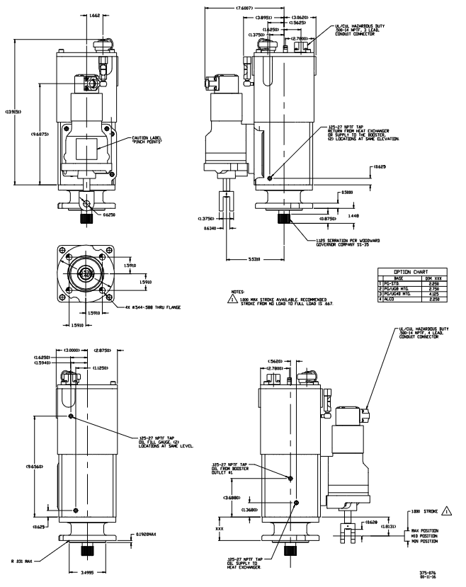
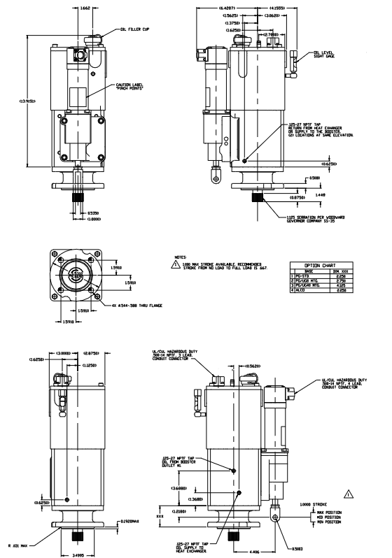
Woodward PGPL electro-hydraulic actuator/driver(37519 G version)
Alternative value: Used to replace traditional hydraulic mechanical governors such as PG-PL, PGD, PGL, etc., retaining the convenience of the original PG type transmission and connecting rod system, while possessing high precision and flexibility of electronic control.
Woodward PGPL electro-hydraulic actuator/driver(37519 G version)
Product core positioning and application scenarios
1. Core positioning
Technology type: Electro hydraulic integrated actuator, including proportional drive interface, capable of receiving electronic controllers (such as Woodward 2301A series, 700 series, etc.) Peak ® The 0-200mA position signal output by the 150 and 505 controllers is controlled by a torque motor and a follow-up pilot valve to drive the output shaft, and coupled with a contactless position sensor to achieve closed-loop control.
Alternative value: Used to replace traditional hydraulic mechanical governors such as PG-PL, PGD, PGL, etc., retaining the convenience of the original PG type transmission and connecting rod system, while possessing high precision and flexibility of electronic control.
2. Scope of application
Adaptation equipment: gas engines, steam turbines (such as power generation turbines, industrial compressor driven turbines);
Hazardous Area Compliance: Compliant with UL certification, suitable for Class I Zone 2, A/B/C/D hazardous environments (models with magnetic electric sensor (MPU) options do not have UL/cUL certification);
Linkage system: It needs to be used in conjunction with an electronic governor, and its core function is to convert electronic control signals into mechanical actions, adjust fuel supply or steam valve opening, and achieve speed/load control.
Core components and technical specifications of the product
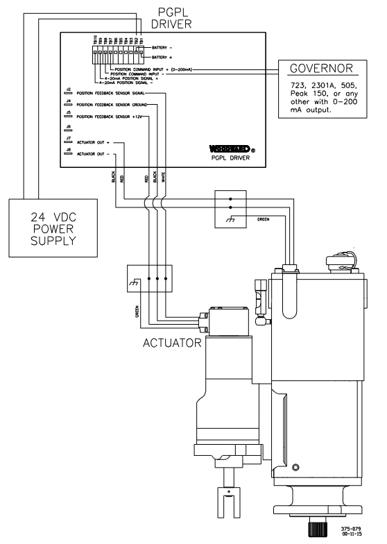
The PGPL system consists of two parts: the "actuator" and the "driver". The former is responsible for mechanical action output, while the latter realizes electrical signal conversion and closed-loop control. The specific parameters are as follows:
1. Actor: the core of mechanical action
(1) Core configuration and performance
Description of Key Parameters for Categories
Linear output of power cylinder: 16J (12ft lb), 23J (17ft lb), 39J (29ft lb), 79J (58ft lb)
Rotation output: 16N · m (12lb ft), 23N · m (17lb ft), 39N · m (29lb ft), 79N · m (58lb ft) linear stroke 25mm (1 inch), rotation stroke 30 °; Available travel/output is 2/3 of the maximum value
Hydraulic system oil pump: PG spur gear pump (low-speed version 0.812 inches thick, ≤ 1000rpm); High speed version 0.562 inches thick,>1000rpm)
Working pressure: Standard 896kPa (130psi), 58ft lb model 1655kPa (240psi) with built-in oil tank (2.5L/2.6 quarts), requires separate oil selection (refer to manual 25071)
Drive required speed: 200-1000rpm (bidirectional rotation, with check valve); Maximum 1500rpm (unidirectional, with plug)
Power: Maximum 375W (0.5hp), oil cooler needs to be selected for high speed or high ambient temperature
Position feedback non-contact Hall effect sensor outputs 3.6-4.4Vdc feedback voltage to the driver, achieving closed-loop control
Environmental adaptability working temperature: -29~+104 ℃ (-20~+220 ℉, limited by oil temperature)
Vibration resistance: Complies with WGC RV2 standard, maximum 7G parallel direction of drive shaft. Shell material: base/column made of cast iron, feedback shell made of aluminum alloy, internal parts made of surface hardened steel
(2) Optional Features
Oil cooler: It needs to be installed when the actuator temperature exceeds 93 ℃ (200 ℉), and is divided into internal and external types;
Booster servo motor: using starting air to provide instant oil pressure, assisting equipment to start quickly;
Magnetic electric sensor (MPU): 1-2 optional, detects the speed of the prime mover through the drive shaft of the governor (cannot be used as a component of the overspeed protection system).
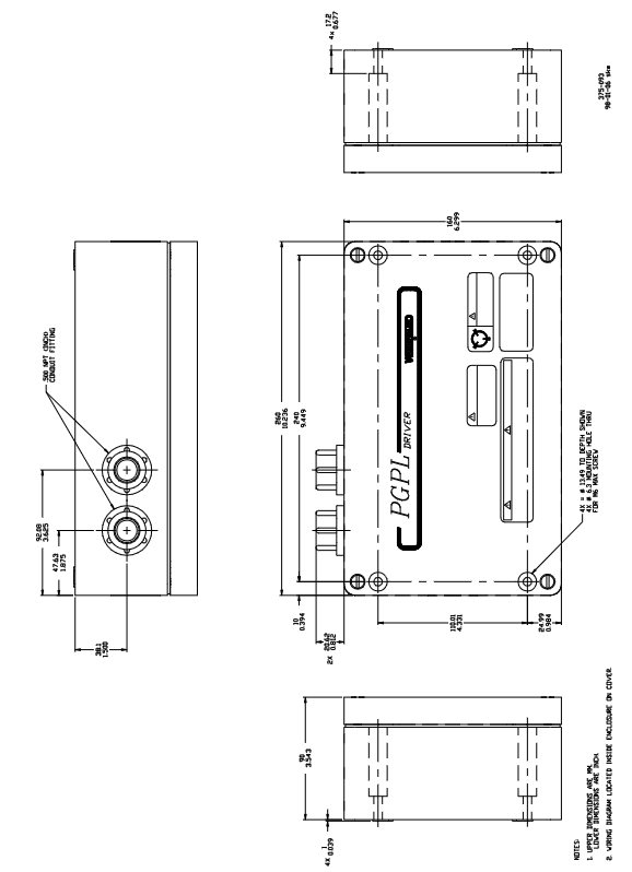
2. Driver: Electrical signal conversion core
(1) Core configuration and performance
Description of Key Parameters for Categories
Electrical signal input/output input: 18-32Vdc power supply, 0-200mA control signal (from electronic speed controller)
Output: 0-200mA drive signal (to actuator torque motor), 4-20mA position feedback signal (to indicator), built-in 210mA current limit to protect torque motor
The closed-loop control receives the 3.6-4.4Vdc signal from the actuator position sensor. After comparing the control signal, the output is adjusted and calibrated before leaving the factory. No field adjustment is required
Installation and environmental enclosure: cast aluminum box (cannot be directly installed on the prime mover)
Working temperature: -40~+70 ℃ (-40~+158 ℉)
Wiring: Use temperature resistant wires with a temperature rating of ≥ 90 ℃, comply with Class I, Zone 2 wiring standards, and require grounding to avoid electromagnetic interference (EMI). Refer to manual 50532
Wire length limit 16AWG (1.5mm ²): battery driver 457m, driver actuator 457m
14AWG (2.5mm ²): Battery driver 610m, driver actuator 610m shielded wire requires twisted pair, one end grounded and the other end suspended
Key requirements for installation and operation and maintenance
1. Installation specifications
(1) Mechanical installation
Attitude: The actuator should be installed vertically or nearly vertically to avoid force on the drive shaft (the actuator should not be placed on the drive shaft);
Transmission connection: The drive shaft should engage freely without any jamming, side load, or excessive axial clearance. The installation bolts should be evenly tightened to avoid shaking;
Connecting rod adjustment: Using 2/3 of the output stroke to achieve "no load full load" adjustment, the remaining stroke is distributed to both ends (ensuring that fuel can be cut off when turned off and maximum fuel can be provided at full load).
(2) Oil selection and maintenance
Oil requirements: viscosity 100-300SUS (at operating temperature), compatible with nitrile, polyacrylic acid, fluorocarbon sealing materials; Recommend using automotive/gas engine oil (such as SAE 10W30, 15W40) to avoid pollution;
Oil change cycle: Under normal working conditions, it should be replaced every year. In harsh environments (high temperature, high pollution), the cycle needs to be shortened; When changing the oil, it is necessary to drain it while it is hot, rinse it with a clean solvent (such as kerosene), and then add new oil.
(3) Electrical installation
Caution in hazardous areas: Do not plug or unplug connectors when live, and replacement parts must meet the requirements of Class I, Zone 2;
Grounding: Drivers and actuators need to be separately grounded to avoid parallel wiring with high voltage/high current wires and reduce EMI interference.
2. Initial operation and troubleshooting
(1) Initial operation steps
Confirm that the oil level is normal, there is no leakage, and the connecting rod is connected correctly;
Set the "low-speed start" mode on the electronic governor and prepare emergency shutdown measures;
Start the prime mover and gradually adjust the governor to the rated speed to ensure that the actuator operates linearly and without any jamming;
Verify closed-loop control: Change the control signal and check if the actuator output matches the feedback signal (10 ± 5mA corresponds to the minimum position, 175 ± 10mA corresponds to the maximum position).
(2) Common faults and solutions
Possible causes of symptoms and solutions
Unable to start/fuel rack does not open, actuator has no electrical signal, oil pump steering error, low oil level, connecting rod stuck. Check power and control signals; Confirm the direction of oil pump rotation; Oil replenishment; Repair the connecting rod
Slow action/delayed response, low speed (<200rpm), improper oil viscosity (too thin/too thick), worn oil pump, increasing speed or installing a boost servo; Replace the compatible oil; Repair/replace oil pump
Calibrate the connecting rod again due to the fluctuation of the prime mover (traveling/surging), nonlinearity of the connecting rod, oil contamination/foaming, and inaccurate parameters of the electronic governor; Change the oil; Adjust the parameters of the speed controller
Overheating of the actuator, high ambient temperature, driving speed exceeding 1500rpm, and installation of an oil cooler for oil oxidation; Reduce the rotational speed; Replace antioxidant oil
Principles of System Control and Safety Design
1. Control logic (closed-loop feedback)
Signal input: The electronic governor outputs a 0-200mA control signal to the driver based on the speed/load requirements;
Signal conversion: The driver converts the control signal into a 0-200mA driving current and sends it to the torque motor of the actuator;
Mechanical action: The torque motor drives the pilot valve, controls the flow of high-pressure oil to the power cylinder, and drives the output shaft action (adjusts the fuel/steam valve);
Feedback loop: The position sensor of the actuator converts the actual position into a 3.6-4.4Vdc voltage signal and feeds it back to the driver; The driver compares the control signal with the feedback signal, adjusts the output current until they match, and achieves precise positioning.
2. Security protection design
Power loss protection: When the control voltage is lost, the torque motor has no magnetic force, the spring pushes the pilot valve to release oil, and the power cylinder resets to the "minimum fuel" position to prevent the prime mover from overspeeding;
Overspeed independent protection: It is explicitly required that the prime mover be equipped with an overspeed shutdown device independent of the PGPL system (not dependent on the MPU of the actuator) to avoid loss of control caused by actuator failure;
Dangerous area protection: The shell is sealed and the wiring meets explosion-proof standards to prevent sparks from igniting dangerous gases.
Product Support and Services
1. Service Options
Quick replacement/exchange: Provide replacement parts of the same model within 24 hours to reduce downtime;
Fixed cost maintenance/renovation: Clearly define the maintenance cost in advance and restore it to a "near new product" state after maintenance;
Spare parts ordering: The model and serial number (indicated on the nameplate) of the actuator/driver must be provided to ensure that the spare parts match.
2. Compliance and Document Reference
Certification: UL (Class I, Zone 2), compliant with EU Machinery Directive 98/37/EC (without CE marking);
Related manuals: 25071 (hydraulic oil selection), 36692 (power cylinder specifications), 36693 (base specifications), 50532 (EMI control).
- ABB
- General Electric
- EMERSON
- Honeywell
- HIMA
- ALSTOM
- Rolls-Royce
- MOTOROLA
- Rockwell
- Siemens
- Woodward
- YOKOGAWA
- FOXBORO
- KOLLMORGEN
- MOOG
- KB
- YAMAHA
- BENDER
- TEKTRONIX
- Westinghouse
- AMAT
- AB
- XYCOM
- Yaskawa
- B&R
- Schneider
- Kongsberg
- NI
- WATLOW
- ProSoft
- SEW
- ADVANCED
- Reliance
- TRICONEX
- METSO
- MAN
- Advantest
- STUDER
- KONGSBERG
- DANAHER MOTION
- Bently
- Galil
- EATON
- MOLEX
- DEIF
- B&W
- ZYGO
- Aerotech
- DANFOSS
- Beijer
- Moxa
- Rexroth
- Johnson
- WAGO
- TOSHIBA
- BMCM
- SMC
- HITACHI
- HIRSCHMANN
- Application field
- XP POWER
- CTI
- TRICON
- STOBER
- Thinklogical
- Horner Automation
- Meggitt
- Fanuc
- Baldor
- SHINKAWA
- Other Brands
- UniOP
- KUKA
- Iba
-
 Schneider LC1F500P7 Contactor 500A
 -
 Mitsubishi GT2512-STBA GT2512-STBD HMI
 -
 Omron NJ1019000 Machine Automation Controller
 -
 Siemens 6SN1112-1AC01-0AA1 Power Module
 -
 Eaton AE16KNS0AB Bimetallic Overload Relay
 -
 ABB 3bse036456r1 Ai825 Analog Input 4 Ch
 -
 Fuji Electric 7MBR50SB120-50 IGBT Module
 -
 Schneider XPSMC32ZP Safety Relay
 -
 Siemens 3VL4740-2AA36-0AA0 Circuit Breaker
 -
 ABB PharpSFan03000 Mpsiii Fan System Monitor
 -
 Honeywell DPCB21010002 IRTP131 PCB
 -
 Siemens 6ES7214-1HG40-0XB0 CPU 1214C
 -
 Siemens 6ES7350-1AH03-0AE0 FM 350-1
 -
 PILZ PNOZ mm0.1p 772001 Safety Relay
 -
 E2V EVX12DS130AGC 12DS130 Module
 -
 Siemens 3RT5066-6AB36 Contactor
 -
 HIRSCHMANN RS20-0800T1T1SDAEHC09.1.00 Switch
 -
 Q4XTILAF500-Q8 Laser Range Sensor
 -
 OMRON CVM1-BC103 Base Unit 145752
 -
 CAREL RITC400001 Card
 -
 Eaton LZMN3-AE400 Molded Case Circuit Breaker
 -
 Fanuc A20B-3300-0031 Control Circuit Board
 -
 Siemens 6ES7450-1AP01-0AE0 S7-400 FM 450-1
 -
 Fanuc A90L-0001-0317/F Spindle Fan Motor
 -
 Schneider TM262L10MESE8T Logic Controller
 -
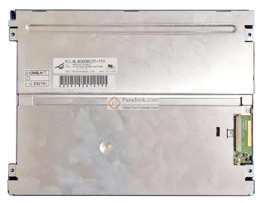 8.4-inch NL8060BC21-06 Industrial Display
 -
 B&R X20CP0411 Compact CPU Control Unit
 -
 Schneider TSX P572634 M Modicon Premium CPU
 -
 Omron NX1P2-1140DT-BA Machine Controller
 -
 Siemens Ams-M35-K202 C8451-A20-A53-7
 -
 Omron FH-2050 Automation Controller
 -
 Omron CJ1W-NCF71 Position Control Unit
 -
 PILZ 777750 Safety Relay
 -
 BES58-P0CA0P-CD0H3PB0 Encoder 85409
 -
 Siemens 3VL5763-1DC36-0AA0 Molded Case Breaker
 -
 FANUC A16B-3200-0010 CPU Card
 -
 HINE DESIGN R94-1164 PLC Control Box 144760
 -
 Siemens PCU 50.5-C 6FC5210-0DF52-2AA0
 -
 PILZ PNOZ M0P Safety Relay 773110
 -
 Fanuc A20B-2101-0820 Control Circuit Board
 -
 Siemens 3SK1121-1AB40 Safety Relay
 -
 Pilz 772120 Safety Relay Expansion Module
 -
 Mitsubishi AX71 Input Module 16 Point
 -
 Siemens 6ES7350-1AH03-0AE0 S7-300 Extension
 -
 Fanuc A16B-3200-0010 CPU Card
 -
 Omron CJ1W-SCW22 Serial Communication Unit
 -
 Siemens 6SN1118-0DM21-0AA0 Control Module
 -
 Renishaw PHC10-3PLUS Controller Module
 -
 ABB AX521 1SAP250100R0001 Module
 -
 Omron NA5-9W001B-V1 PLC Module HMI
 -
 Infineon FF1000R17IE4 IGBT Power Module
 -
 Omron CJ1W-DA08C Analog Output Module
 -
 Omron CJ1G CPU45H CJ1H CPU66H CJ1G CPU43H CJ1W PA202
 -
 Omron CJ1W-DA041 Analog Output Module
 -
 Inductotherm 170-8031 PLC Control Module
 -
 Fuji Electric FPB56HR-A10 Programmable Logic Controller
 -
 Siemens 6SN1145-1BA01-0BA1 Infeed Regenerative Module
 -
 PILZ 777949 PSWZ X1P Safety Relay
 -
 Schneider 140NOM25200 DIO Head-end Adaptor
 -
 Siemens PXC5.E003 Controller BPZ
 -
 Schneider BMXEHC0800 Fast Counting Module 10kHz
 -
 Schneider BMXART0814 Isolated Thermocouple Inputs
 -
 Schneider BMXNOE0100 Ethernet Module 10 100 RJ45
 -
 LMX06-NS05 Sensor Industrial Proximity Switch
 -
 Siemens 6SN1145-1BB00-0FA1 Power Supply 156kW
 -
 Pro-face GP2500-LG41-24V HMI Graphic Panel
 -
Keyence CV-3001 Vision System CV3OO1
-
 Siemens 6GK5204-2BB10-2AA3 Ethernet Module
 -
 Pro-face PFXSP5500TPD 10.4in HMI LCD Display
 -
 Eu Automation 140DRA84000 Modicon Quantum Module
 -
 Siemens 6FC5210-0DF31-2AA0 Sinumerik PCU 50.3-C
 -
 Siemens 6SL3040-1NC00-0AA0 Sinumerik NX10.3 Extension
 -
 Gould AS-884A-111 Modicon 884 Controller
 -
 Allen Bradley 1336E-BRF30-AA-EN-HA2-L5 Impact Drive
 -
 Siemens 6FC5110-0BB02-0AA1 Sinumerik 840D CPU Card
 -
 Pilz 773500 PNOZmulti Expansion Module
 -
 Siemens 6ES7350-1AH03-0AE0 S7-300 Counter Module
 -
 Siemens 6FC5110-0DB01-0AA1 Sinumerik 840D Card
 -
 HPM 1D703-0040 Command 9000 VGA Console Board
 -
 OMRON CJ1W-PTS52 Temperature Unit
 -
 Sacs Technique PCD4.M12 Module
 -
 OMRON CJ1M-CPU11-ETN Ethernet CPU
 -
 OMRON CJ1M-CPU23 PLC CPU Unit
 -
 OMRON NX-SID800 Safety Input Unit
 -
 GE Fanuc Series 90-30 PLC
 -
 OMRON CJ1W-NCF71 Position Control
 -
 OMRON CJ1W-AD081-V1 Analog Input
 -
 OMRON FZ-S2M Vision Camera
 -
 OMRON R88D-UEP20V Servo Driver
 -
 OMRON F500-C10-ETN Vision Controller
 -
 OMRON CS1W-DA041 Analog Output Module
 -
 PRO-FACE GP577R-TC41-24VP HMI Panel
 -
 TRUTZSCHLER RAK 1 492-58.430.000 PLC Module
 -
 OMRON NX-OD5256 Output Module
 -
 Siemens 6AG1214-1AG40-4XB0 PLC
 -
 OMRON CJ1W-AD081-V1 Analog Unit
 -
 OMRON C500-CPU11-E PLC CPU
 -
 OMRON NX-ECC201 EtherCAT Coupler
 -
 OMRON F300-A20S Camera Interface
 -
 Mitsubishi 80173-109-01 PLC Module
 -
 Fanuc A16B-2200-0141 PCB Board
 -
 Lenze EPL10200 PLC Module
 -
 OMRON CJ1M-CPU13 PLC CPU Unit
 -
 Yaskawa SGMPH-04AAA61D-OY Motor
 -
 OMRON NX-SOD400 Safety Output
 -
 Control Techniques V1800 Flux Vector Drive
 -
 Yaskawa SGDH-04AE-OY Servo Drive
 -
 OMRON NT-DRT21 DeviceNet Interface
 -
 OMRON C500-RM001-V1 Remote I/O Master
 -
 OMRON C500-AD006 Analog Input Module
 -
 OMRON 3G3MV-A4055 Inverter Drive
 -
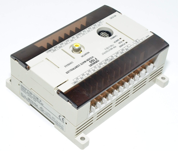 OMRON F150-C15E-3 Vision Mate Controller
 -
 OMRON CS1G-CPU44H PLC CPU
 -
 GE Fanuc DS6800CCIE1E1D CPU Module
 -
 Omron CP1L-M30DR-A PLC CP1W-CIF01 CPU Unit
 -
 Heraeus 585923 2M130 M8 Electrode Assembly Sensor
 -
 Omron C40P-EDT1-D C Series PLC Controller
 -
 Yaskawa SGMGH-09DCA6F-OY Servo Motor SGDH Driver
 -
 Datalogic SG-BWS-T4-MT Safety Control Unit Category 4
 -
 Pro-face PFXLM4301TADDC HMI Controller LT-4301M
 -
 Mitsubishi FX1N-60MR-DS PLC Main Unit 60 I/O
 -
 Omron NJ501-1320 Sysmac Database Connection CPU
 -
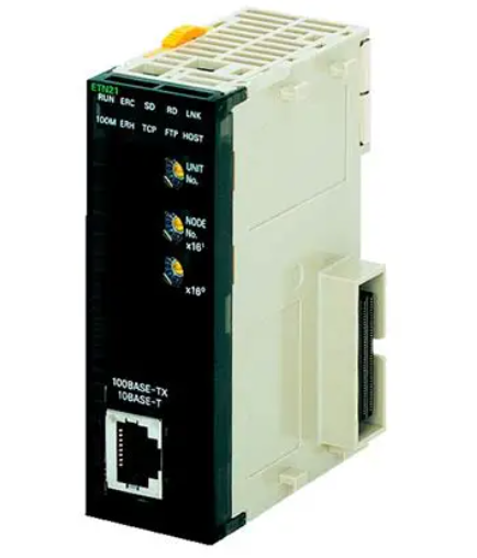
 Omron CJ1W-ETN21 Ethernet Unit CJ Series Module
 -
 Siemens 6ES7517-3AP00-0AB0 CPU 1517-3 PN/DP
 -
 Pasaban MTC-3052 Fast I/O PLC Module
 -
 Mitsubishi FX3U-128MR/ES-A PLC
 -
 OMRON CS1W-CLK21 Controller Link Unit
 -
 Yokogawa ADV151-E63 Digital Input Module


