
Siemens 7XV5653-0BA00 dual channel binary signal transmitter
Siemens 7XV5653-0BA00 dual channel binary signal transmitter
Overview
The operation manual for Siemens 7XV5653-0BA00 dual channel binary signal transmitter covers all aspects of the equipment from basic information to specific operations. It is suitable for technical personnel who have received professional training and have knowledge in the fields of instrumentation, control, and automatic control engineering, providing guidance for the safe installation, commissioning, operation, and maintenance of the equipment.
Basic Equipment Information
(1) Scope of application and compliance standards
Application scenario interference emission requirements Anti interference requirements
Industrial sector EN 50081-2: 1993 EN 50082-2: 1995
Residential sector (residential, commercial trade, small businesses) EN 50081-1:1992 EN 50082-1:1992
(2) Equipment functions and features
Core function: Dual channel bidirectional binary signal transmitter, capable of converting binary signals with a wide range of inputs. The signal status is serially sent to a similar remote converter through duplex optical fibers. The remote converter outputs the information as command contacts in real time, suitable for switch equipment. It can achieve interference free signal transmission through optical fibers, safely detect misoperations or transmission faults, and send signals through alarm relays.
Performance characteristics:
Two isolated binary inputs, with a wide input voltage range (18V-250VDC) and polarity reversal protection.
Two isolation command relays with large switch capacity.
Point to point connection with short operation time (12-118ms), depending on the data rate.
Fiber optic connection can achieve interference free transmission even in high electromagnetic interference environments.
Protocol communication has monitoring function and transmission security.
Long transmission distance, up to 3km under multimode fiber (62.5/125 μ m), and up to 100km under single-mode fiber when cascaded with 820/1300nm converter 7XV5461-0BA00.
Integrated wide range power supply unit with alarm contacts.
(3) Operation mode
Operation mode, working mode, alarm and signal transmission characteristics
Full duplex mode binary information can be transmitted in both directions simultaneously, such as for direction comparison or signal comparison (according to delivery status). In case of power failure, alarm relay M1 will be released; When no remote converter signal is received, the red LED (ERR) lights up and the alarm relay M1 is released; When running through a modem, if the data connection is interrupted for any reason, to avoid overloading the modem, the device will only send more data after 15 seconds, but will immediately transmit when the binary input signal changes
Half duplex mode binary information is only transmitted unidirectionally through fiber optic cables, requiring only one fiber optic transmitter from the input device to the output device (S2/DIP 7 is set to "transmit only"): in the event of a power failure, alarm relay M1 is released and the transmission link from the transmitter is not monitored;
Receiver (S2/DIP 7 set to "send/receive"): When there is a power failure, the alarm relay is released; When no transmitter signal is received, the fault indicator (red LED: ERR) stays on and the alarm relay M1 is released
(4) General Data and Data Transmission
Auxiliary power supply: Connect DC or AC auxiliary power supply through 2 terminals (N/L-L1/L -), with a wide range of auxiliary power supply (24-250V DC, 60-230V AC), without the need for internal jumper wires, and can be connected to all common substation batteries or AC mains voltage; There is a working voltage LED indicator light (green LED: RUN) on the front of the device, indicating whether the device is operating normally.
Data transmission: The optical interface adopts positive logic (light off in idle state), and the incident light is considered as a valid signal (=1, high level); Built in switch, compatible with negative logic system (fiber optic interface), factory set to positive logic (light off in idle state), and both converters must use the same logic. It is recommended to keep the factory settings.
Fiber optic connection: Fiber optic is connected to the converter through an ST connector.
RS232 interface connection: When connecting to the RS232 interface, it is necessary to disconnect the fiber optic transmission and set the communication to a serial interface; It can be connected to the serial interface of the converter through the serial 7XV5100-4 cable. If other cables are used, the 7th and 8th pins of the bridging cable need to be bridged, and the 1st and 4th pins (X1 of BST) are not assigned.
(5) Binary input
The two binary inputs (BI-1 and BI-2) have a wide input voltage range, with a logic high level "1" of 24V-250V DC (-15%,+20%) and a pickup threshold of 18V. In special cases (such as long-distance unshielded lines and high electrical interference), the threshold can be increased; The logic low level '0' is a voltage level below the threshold.
The corresponding yellow LEDs (BI-1, BI-2) light up when the corresponding binary input is activated (in a logic high state); The LED K1 and K2 display the status of the output contacts, which is set by the binary input in the serial telegram transmitted by the remote converter through fiber optic or RS232 connection (such as a modem with RS232 interface).
Application scenarios
(1) Application examples
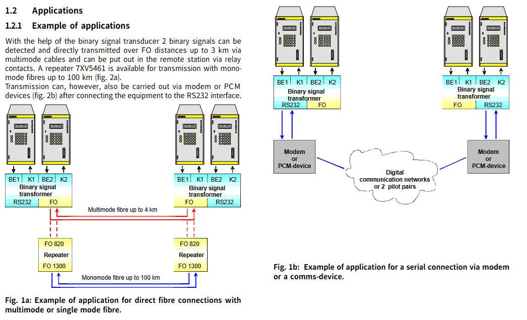
With the help of this binary signal transmitter, two binary signals can be detected and transmitted directly to a distance of 3km through multimode cables and optical fibers, and output through relay contacts at remote stations; If single-mode fiber is used for transmission up to 100km away, it can be paired with repeater 7XV5461.
After connecting the device to the RS232 interface, it can also be transmitted through a modem or PCM device.
(2) Binary signal transmission through leased lines
1. Dual line operation using LOGEM928 and LGH28.8D modems (firmware 4.13)
DIP switch settings for modems: Before setting, the modem needs to be turned off. After setting is complete, the modem needs to be turned on for the new settings to take effect.
Modem initialization: Before debugging, the modem needs to be initialized, preferably with the help of a terminal program (such as Hyperterminal); Use a zero modem cable to connect the PC and modem running the terminal program, reset the modem before initialization (press the switch when connecting the auxiliary power supply until the LED "A/O" flashes); Enter a specific text string in the super terminal and send it. The modem will reply with "OK", and then you can disconnect the modem from the PC interface and connect its serial interface to the converter's serial interface.
The string corresponding to 19200 baud rate:
Modem A:AT &V NO Q0 &D0 F40 S51=11 %C0 S20=0 &L2 E0 Q1 &W
Modem B:AT &F0 N0 Q0 &D0 F40 S51=11 %C0 S20=0 &L3 E0 Q1 &W
Command Explanation:
|Command | Meaning|
|&F0 | Load factory settings|
|N0 | Normal mode (no data compression, no error correction)|
|Q0 | No traffic control|
|&D0 | Ignore control cable S1/108|
|F40 | Transmission mode V.34|
|S51=11 | Fixed baud rate of terminal device (RS232 interface)|
|%C0 | No data compression|
|S20=0 | Ignore symbols in the command phase|
|&L2 | Calling modem|
|&L3 | Called modem|
|E0 | No echo display|
|Q1 | Close result code|
|&W | Save the settings to the EEPROM of the modem|
Connectors and cables for dual line leased line operation: Use the accompanying cable labeled "leased line" to connect the RJ-11 connector to the socket labeled "LEASED", and connect the other end of the cable to the TAE-N encoded telephone outlet box in a specific manner (TAE-N 1 # 1 to TAE-N 2 # 1, TAE-N 1 # 2 to TAE-N 2 # 2).
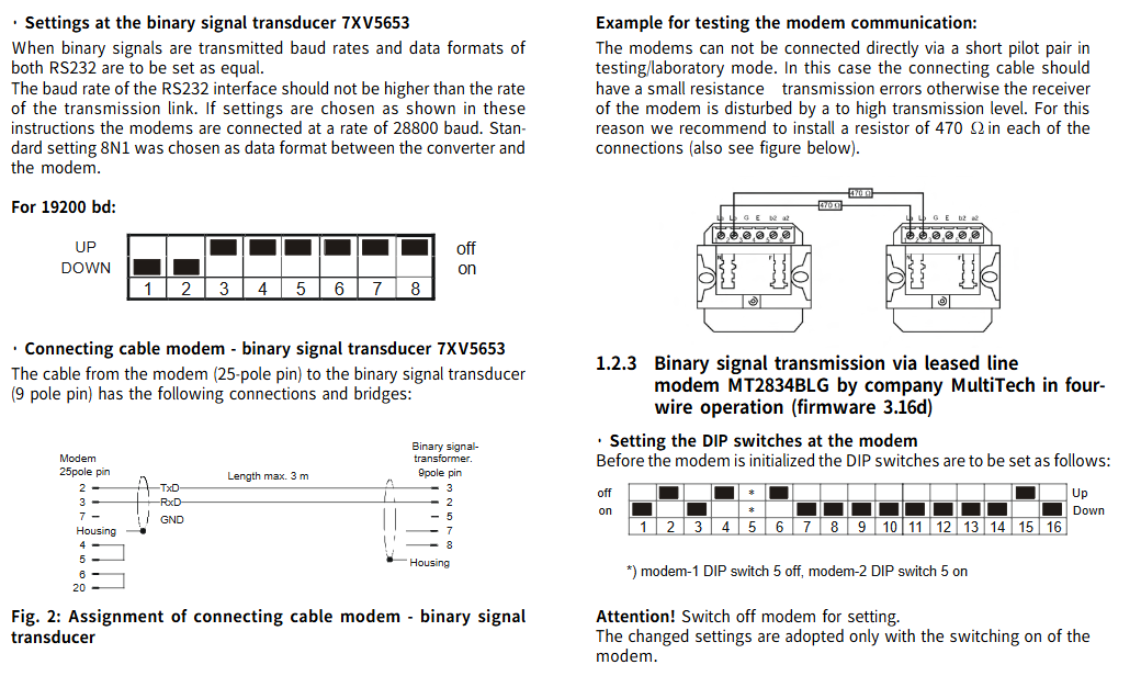
Setting of binary signal transmitter 7XV5653: When transmitting binary signals, the baud rate and data format of the two RS232 should be set to be the same; The baud rate of the RS232 interface should not be higher than the speed of the transmission link. When setting according to the instructions, the modem should be connected at a 28800 baud rate, and the data format between the converter and the modem should be set to 8N1 as the standard. The 19200 baud rate corresponds to specific DIP switch settings (DOWN/UP, off/on status).
The connection cable for modem binary signal transmitter 7XV5653: The cable from the modem (25 pin) to the binary signal transmitter (9-pin) has specific connection and bridging methods, with a maximum length of 3m.
Example of modem communication test: In test/laboratory mode, the modem cannot be directly connected through a short guide wire, otherwise excessive transmission levels will interfere with the modem's receiver. It is recommended to install a 470 Ω resistor in each connection.
2. Four wire operation using MultiTech's MT2834BLG modem (firmware 3.16d)
DIP switch settings for modem: Before setting, the modem needs to be turned off. After setting is complete, the modem needs to be turned on for the new settings to take effect. DIP switch 5 for modem 1 is set to off, DIP switch 5 for modem 2 is set to on, and other switches have specific off/on states (up/down direction).
Modem initialization: Before debugging, the modem needs to be initialized, preferably with the help of a terminal program (such as Hyperterminal); Use a zero modem cable to connect the PC and modem, input specific data (AT&FE0 # F0 $SB19200MB19200&E14&E3&W0) into the super terminal and send it, and the modem will reply with "OK".
Command Explanation:
|Command | Meaning|
|If the connection is correct, the modem replies with "OK"|
|&F | Load factory settings|
|E0 | No echo display|
|#F0 | Fixed baud rate of terminal device (RS232 interface)|
|Stable performance speed MB19200 | Fixed baud rate between modem 1 and modem 2|
|&E14 | Disable data compression|
|&E3 | Turn off traffic control|
|&W0 | Save Settings|
Connectors and cables for four line leased line operation: Use the accompanying cable labeled "leased line" to connect the RJ-11 connector to the socket labeled "LEASED", and connect the other end of the cable to the TAE-N encoded telephone outlet box in a specific way (with specific correspondence between TAE-N 1 and TAE-N 2 pins).
Technical parameters
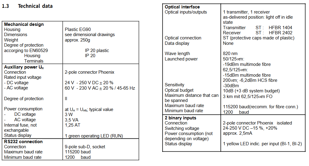
Parameter Category Specific Parameters
Mechanical Design - Shell: Plastic EG90
-Size: See size chart
-Weight: Approximately 250g
-Protection level (according to EN60529): enclosure IP20, terminal IP20
-Protection level: Level II
Power consumption - DC voltage (UH=UHN, typical value): 3W
-AC voltage (UH=UHN, typical value): 3.5VA
Internal fuse cannot be replaced, 1.25AT
Status display: 1 green working LED (RUN)
RS232 connection - Connection method: 9-pin sub-D socket
-Maximum baud rate: 115200 baud
-Minimum baud rate: 1200 baud
Optical interface - optical input/output: 1 transmitter, 1 receiver, factory state: light off when idle; Transmitter ST: HFBR 1404; Receiver ST: HFBR 2402
-Optical connection: ST (plastic protective cover)
-Data display: None
-Wavelength: 820nm
-Transmission power: 50/125 μ m multimode fiber: -19dBm; 200 μ m HCS fiber: -6.2dBm
-Sensitivity: -30dBm
-Light budget: 10dB (+3dB system budget)
-Maximum transmission distance: 625/125 μ m fiber optic 3km
-Maximum baud rate: 115200 baud (recommended for fiber optic connections); Approximately 2.5mA at 1200 baud
2 binary inputs - Connection method: 2-pole connector Phoenix, isolated
-Switching voltage: 24-250V DC (-15%,+20%)
-Power consumption (voltage independent): approximately 2.5mA
-Status display: 1 yellow LED per input (BI-1, BI-2)
2 instruction outputs (relays) - Relay type: MSR relay (K1, K2), 1 floating normally open relay
-Connection method: 2-pole terminal Phoenix
-Switching voltage (rated voltage): 250V AC/DC
-Switch capacity: 5A (long-term); 30A (0.5s, if the relay displays); 50-270W (depending on voltage), each 1000VA
-Switching current: Long term 1A
-Status display: 1 yellow LED (K1, K2)
-Fiber optic operation response time (from binary input event of transmitter A to binary output response of transmitter B): 1200 baud 118ms, 2400 baud 63ms, 4800 baud 34ms, 9600 baud 20ms, 19200 baud 17ms, 38400 baud 15ms, 57600 baud 14ms, 115200 baud 12ms (recommended for direct fiber optic connection)
-Response time for modem operation (MT2843BLG modem) (binary signal event from transmitter A to binary signal response from transmitter B): 9600 baud 102ms, 19200 baud 71ms
1 fault indicator output relay - connection method: 2-pole terminal Phoenix
-Switching voltage (rated voltage): 250V AC/DC
-Switch capacity: 30W/VA
-Switching current: Long term 1A
-Fault indicator: No specific parameters
Safety (according to DIN EN 61010 Part 1) - Overvoltage category: Class III (3.7kVAC/5.2kVDC)
-Pollution level: Level 2
-Fire rating (according to UL 94): V0 level
Dielectric Loss Test (EN61010) - Power to Relay to Binary Input: 3.1kV DC/1s (with bypass capacitor)
-Power supply to RS232: 2.0kV AC/50Hz/1s (without bypass capacitor)
-RS232 to relay to binary input: 2.0kV AC/50Hz/1s (without bypass capacitor)
Electromagnetic compatibility test - Electromagnetic immunity test: EN 50082-2
-Electromagnetic emission test: EN 50081-1
Permissible environmental conditions - Operating temperature: -5 ° C to+55 ° C
-Storage temperature with factory packaging: -25 ° C to+70 ° C
-Transportation temperature with factory packaging: -25 ° C to+70 ° C
-Humidity: 10% -93% (no condensation allowed)
-Air pressure: 0-3000 ASL
Functional Unit Description
(1) Overall structure
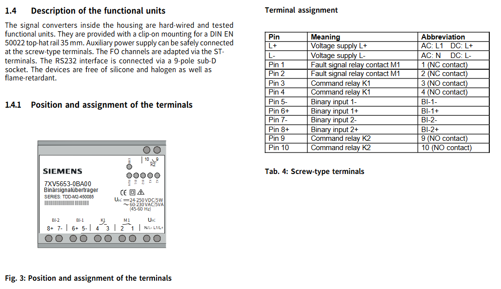
The signal converter inside the casing is a hard wired and functionally tested unit, equipped with snap on mounting components for DIN EN 50022 35mm top cap rails; The auxiliary power supply can be safely connected through screw terminals; Fiber channel is adapted through ST terminals; The RS232 interface is connected through a 9-pin sub-D socket; The device does not contain silicone and halogens, and has flame retardancy.
(2) Terminal position and allocation
The terminal positions have a specific layout (see Figure 3), and each pin has a clear meaning and abbreviation, as follows:
|Pin | Meaning | Abbreviation|
|L+| Power supply L+| AC: L1; DC:L+|
|L - | Power supply L - | AC: N; DC:L-|
|Pin 1 | Fault signal relay contact M1 | 1 (normally closed contact)|
|Pin 2 | Fault signal relay contact M1 | 2 (normally closed contact)|
|Pin 3 | Command relay K1 | 3 (normally open contact)|
|Pin 4 | Command relay K1 | 4 (normally open contact)|
|5- Pin | Binary Input 1- | BI-1-|
|6+pins | Binary input 1+| BI-1+|
|7- Pin | Binary Input 2- | BI-2-|
|8+pins | Binary input 2+| BI-2+|
|Pin 9 | Command relay K2 | 9 (normally open contact)|
|Pin 10 | Command relay K2 | 10 (normally open contact)|
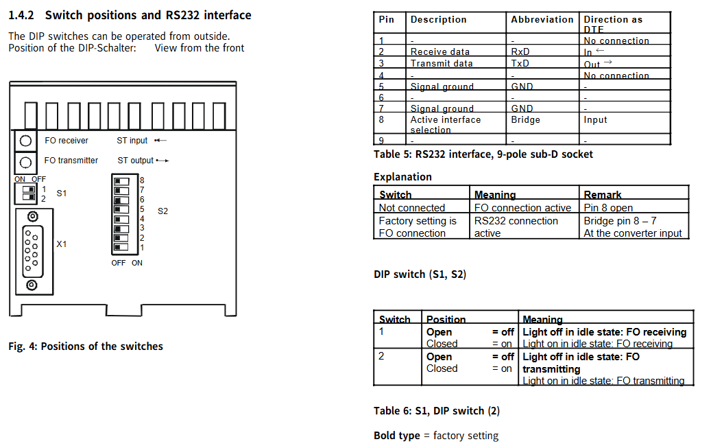
(3) Switch position and RS232 interface
DIP switch operation: DIP switches can be operated from the outside and have specific position layouts (see Figure 4).
RS232 interface (9-pin sub-D socket): Each pin has a clear description, abbreviation, and direction as DTE, as follows:
|Pin | Description | Abbreviation | Direction as DTE|
| ---- | ---- | ---- | ---- |
|1 | None | None | No connection|
|2 | Receive data | RxD | Input (←)|
|3 | Send Data | TxD | Output (→)|
|4 | None | None | No connection|
|5 | Signal Ground | GND|-|
|6 | None | None|-|
|7 | Signal Ground | GND|-|
|8 | Activity Interface Selection | Bridge | Input|
|9 | None | None|-|
Interface selection instructions:
|Connection status | Interface status | Remarks|
|Not connected | Fiber optic connection activated | Pin 8 open circuit, factory set to fiber optic connection|
|Bridge | RS232 connection activation | Bridge pins 8-7 at the input of the converter|
DIP switch (S1, S2) function:
S1 (2-position DIP switch):
|Switch | Position | Meaning|
|1 | Open circuit (off) | The light goes out when the fiber optic receiver is idle|
|1 | Closed (on) | The light is on when the fiber optic receiver is idle|
|2 | Open circuit (off) | The light goes out when the fiber optic transmission is idle|
|2 | Close (on) | The light is on when the fiber optic transmission is idle|
S2 (8-bit DIP switch): By combining different DIP switches (DIP1-DIP8), multiple functional settings can be achieved, including baud rate (1200-112200 baud), data format (8E1: 8-bit data, even parity, 1-bit stop bit); 8N1: 8-bit data, no checksum, 1-bit stop bit), MA function (block MA, enable MA), test mode (test mode on, test mode off), working mode (only transmit, send/receive), boot loader (boot loader on, boot loader off), specific combinations are shown in Table 7, bold indicates factory settings.
Special mode explanation:
Test mode enabled: The binary signal transmitter performs self-test. If the binary input is activated (voltage applied), the binary LED (BI-1 or BI-2) lights up, and the corresponding relay (K1 or K2) and associated LED (K1 or K2) are activated; The memory test diagnosis and DIP switch position will be output to the serial interface (RS232), which can be displayed through the terminal program running on the PC.
Test mode off: The binary signal transmitter is ready to operate normally.
Blocking MA: Blocking message output, not controlling relay.
Enable MA: Normal operation, message output is not blocked.
Only transmitting: Binary signal transmitters only function as transmitters and do not report missing incoming signals as communication errors.
Baud rate setting: query the baud rate once after power on (DIP switch position); In the activated test mode, the baud rate will be continuously queried and reset; Set baud rate during operation: Set the baud rate through DIP switch 0-2 and briefly switch the on/off state of DIP switch 6 (test mode).
(4) Adjustment of picking threshold for binary input
To adjust the threshold of binary input, the binary signal transmitter needs to be turned on and the jumper changed. When the device is turned on, it is prohibited to run and the power supply needs to be disconnected first.
Steps for adjusting jumper position: Disconnect the power supply of the device → Remove the housing cover (carefully push the buckle of the cover towards the inside of the device with a small screwdriver) → Change the jumper position according to Table 8 → Clip the cover back to its original position.
Corresponding relationship between jumper position and picking threshold:
|Jumper | Position | Pick threshold | Binary input|
|X100|1-2|17V|1(BI-1)|
|X100|2-3|70V|1(BI-1)|
|X200|1-2|17V|2(BI-2)|
|X200|2-3|70V|2(BI-2)|
(5) Dimensional drawing
The equipment has specific size specifications, as shown on page 32 of the document, including the size parameters of components such as clips and terminals (such as 95mm, 105mm, 90mm, etc.).
Order data
Name, Model, Specification
Dual channel binary signal transmitter 7XV5653-0BA00 with 2 binary inputs, 2 command inputs, and 1 fault signal output (via terminals)
Installation and Debugging
(1) Installation precautions and steps
Installation warning: Some components of electrical equipment carry dangerous voltage during operation. Ignoring the operating instructions may result in serious personal injury or property damage. The installation and electrical connection of the equipment are only allowed to be carried out by qualified personnel, and all warnings must be strictly followed; Do not directly stare at the fiber optic transmission diode while wearing optical assistive devices; Prohibit operation when the device is turned on.
Installation requirements:
The installation location should be free of vibration and comply with the allowed ambient temperature (working or functional temperature, see technical parameters). Ignoring the temperature range required for normal function may lead to equipment failure and signal converter failure.
The equipment has a plastic casing and belongs to overvoltage category III according to DIN EN 61010 Part 1.
The signal transmitter can be installed on a 35mm top cap guide rail (according to DIN EN 50022) with a snap fit.
The equipment is only allowed to operate within a closed enclosure or cabinet, and the installation location is only accessible to qualified personnel.
Installation steps: Clip the binary signal transmitter onto the top cap guide rail using a snap on mounting component.
(2) Connection requirements and steps
Connection specifications: Electrical connections must comply with the installation regulations for high current devices, as well as VDE0100 and VDE0160 standards.
Power connection: The auxiliary power supply of the equipment needs to be equipped with an external isolation switch (for power safety isolation) and a safety device (fuse, 2AT or 4AT). The external isolation switch should be labeled accordingly, and the safety circuit breaker can simultaneously perform both functions.
Cable requirements:
Cable cross-section (single core cable or multi stranded wire): 0.5mm ² -2.5mm ².
Suggested stripping length: 5mm.
Multi strand wire connections require the use of insulated wire end sleeves (to avoid wire unraveling).
Fiber optic connection: only use fiber optic cables prepared according to regulations; Refer to the technical specifications for the type of optical fiber; Must comply with the allowed light budget (see technical specifications); When installing optical fibers, it is necessary to follow the prescribed bending radius.
Connection steps:
Connect the auxiliary power supply to terminals UH (DC: L+/AC: L1) and (DC: L -/AC: N).
Connect the fiber optic cable to the fiber optic receiver and transmitter through ST type terminals, or connect an RS232 cable.
(3) Debugging steps and requirements
Check if the operating data matches the values on the nameplate and do not make any changes to the equipment.
After completing the installation and connection, connect the auxiliary power supply, and the binary signal transmitter can be put into use. The green LED "RUN" will light up.
Setting up and maintenance
(1) Equipment settings
All settings of the binary signal transmitter (except for the pickup voltage of the binary input) can be made through an external DIP switch without opening the casing; The picking voltage setting for binary input requires opening the casing (see section 1.4.2); Specific setup instructions can be found in section 1.2.2 (setup of binary signal transmitter 7XV5653).
(2) Equipment maintenance
Binary signal transmitters do not require maintenance, and do not use any liquid reagents or substances during cleaning.
- OMRON
- ABB
- General Electric
- EMERSON
- Honeywell
- HIMA
- ALSTOM
- Rolls-Royce
- MOTOROLA
- Rockwell
- Siemens
- Woodward
- YOKOGAWA
- FOXBORO
- KOLLMORGEN
- MOOG
- KB
- YAMAHA
- BENDER
- TEKTRONIX
- Westinghouse
- AMAT
- AB
- XYCOM
- Yaskawa
- B&R
- Schneider
- KONGSBERG
- NI
- WATLOW
- ProSoft
- SEW
- ADVANCED
- Reliance
- TRICONEX
- METSO
- MAN
- Advantest
- STUDER
- DANAHER MOTION
- Bently
- Galil
- EATON
- MOLEX
- DEIF
- B&W
- ZYGO
- Aerotech
- DANFOSS
- Beijer
- Moxa
- Rexroth
- Johnson
- WAGO
- TOSHIBA
- BMCM
- SMC
- HITACHI
- HIRSCHMANN
- Application field
- XP POWER
- CTI
- TRICON
- STOBER
- Thinklogical
- Horner Automation
- Meggitt
- Fanuc
- Baldor
- SHINKAWA
- Other Brands
- UniOP
- KUKA
- Iba
- Beckhoff
- ADLINK
-
 Lust Antriebstechnik LTI Drives VF1204S Inverter
 -
 Lust LTI Drives CDE32.008 C3.0 Positioning Controller
 -
 LTI Drives LUST Servo One C-5633 D-35633
 -
 Lust LTI Drives CDA34.008.C1.3 Servo Controller 3kW
 -
LTI CDF30.008 C2.6 Servo Drive 10962161
-
 LUST LTi Drives CDB32.004 C2.3 SH Servo Drive
 -
 Lust LTi Drives CDE34.010 D2.0 Servo Drive
 -
 LTi Motion CDA32.006 Servo Drive with CM-CAN1
 -
Lust LTI Drives CDB32.008 C2.3 Servo Controller
-
 LTi CDE34.017.W3.0 Servo Drive
 -
 LUST LTI LST-074-2-30-320/T1 Servomotor
 -
Lust LTi CDF30.002 C3.0 Positioning Controller
-
 LTi DRIVES CDF30.008.C2.4 Drive
 -
 LUST LTI CDB32.008 W2.4 BR PC1 Drive
 -
 LTi SO84.004.0002.0100.2 Servo Controller
 -
 LTi SO84.012.0030.0011.2 ServoOne Drive
 -
LTI Drives LUST Servo One C-5633 D-35633
-
 LTi DRiVES c-line Smart Card A028.V01.1
 -
LUST LTI CD A34.008 W1.4 BR Drive
-
 LUST LTI LSH-097-2-30-560/T1 Servomotor
 -
LUST LTI LST-074-2-30-320/T1 Servomotor
-
LUST LTi CDB32.004 C2.4.SH Servo Drive
-
 LTI Drives PM-E40.2DRA054P Pitch Inverter
 -
Lust LTI Drives CDF30.008 Servo Drive 8673548
-
LTI Drives CDF30.002.C0.7 Servo Controller
-
 Lust LTI Drives CDB32.008.W2.4 Servo Drive
 -
Lust LTI Drives CDB34.003 Servo Motor Driver
-
Lust LTI Drives CDA32.004 Servo Drive 3084456
-
Lust LTI Drives CDE34.005.W2.2 Servo Drive
-
Lust LTI Drives CDA34.006.W3.0 Servo Drive
-
 LTI Drives CDF30.008.C2.4 Servo Controller
 -
LTI Drives Lust CDB32.004.C2.4.SH Servo Drive
-
 Delta Design 1666339-501 Micro Stepper PCB 114970
 -
 APEXEL 100X Microscope Mobile LED Pocket Lens
 -
 Micro Innovation XV-152-D4-10TVR-10 Touch Screen
 -
 Micro Innovation XVH330-57MPI-1-10 Touch Screen Glass
 -
 Delta Design 1666339-501 Micro Stepper PCB 114967
 -
Micro Design MC100-MA V3 Board
-
 Delta Design 1666339-501 Micro Stepper PCB 114968
 -
Delta Design 1666339 PCB Micro Stepper ITR 116487
-
Micro Innovation XV-440-10TVB-1-10 Panel
-
 Sterling 9B21-3 Micro Switch Durable Design
 -
ATTINY104-XNANO Microchip AVR Prototype Board
-
 Delta Design 1666339 Micro Stepper PCB ITR 116539
 -
Super Micro X7SBJ Industrial Main Board
-
 Delta Design NMS BD 1698437-501 Stepper Board
 -
 Micro Innovations Turbo Track Keyboard KB420BL
 -
Micro Design PC-1 PC-1-H-DU010 Operator Panel
-
 TCI MICRO MD 250mA 7W Dimmable LED Driver
 -
 Delta Design 1666339 Micro Stepper PCB ITR 116485
 -
 Delta Design NMS BD 1698437-501 Stepper Board
 -
 Life Instruments 714-1120-1U Micro Curette
 -
Delta Design 1657925-501 Micro Processor PCB
-
Micro 100 RTC-125-2 Carbide Engraving Tool
-
 Micro Design Inc. 2106022 Liquid Level Sensor PCB
 -
Periodontal Micro Surgical Full Kit 20pc Blue Titanium K1004
-
 Micro Innovation XN-2DO-24VDC-0.5A Module
 -
Wide Innovative Technology PS-01 Micro Positioner Set
-
 HU FRIEDY NH5020 Castroviejo Needle Holder Set
 -
Moeller Micro Innovation XV-232-57BAS-1-10 Touch Screen
-
 Micro Design System MCVP-300VR Control Module 24VDC
 -
Scanlan 3003-234-1 Titanium Jacobson Needle Holder
-
 Micro Innovation XV-102-B0-35TQR-10-PLC Panel
 -
Promot Micro Design 3x8 Output 2187F
-
 Micro Innovation LIC-SW-Galileo 91 30 000600 License Certificate
 -
 Micro Design AI0486.A4-50 Control Module Board
 -
 Micro Innovation XN-2DO-24VDC-0.5A Output Module
 -
 Micro Design Not-Aus Relais AE 8.96 AE 896
 -
Micro Innovation CPC-600M-10 Ferag Touch Panel HMI
-
 Micro Design System 96-002-09/1 Adapter 18 Bit
 -
Micro Design LK3160 AI0486 Motherboard
-
Micro Design System 96-002-01/2 GF-1 CPU Board
-
 Micro Design Systems CF1-10TVA-100 Micro Panel
 -
Eaton Micro Innovation XP-702-C0-15TXI-10 Panel
-
HU FRIEDY Castroviejo NH5020 Needle Holder
-
 MPM Micro Precision 3.BMT100 P02 Balancing Station
 -
 Micro Innovation GF1-10TVD-101 Touch Panel
 -
Micro Innovation XV-102-B0-35TQR-10-PLC
-
Micro Innovation XP-601-15T-10 Touch Panel
-
 Micro Innovation License Certificate 9130000650 LIC-SW-MXPRO
 -
Micro Innovation XVC-601-GTI-15-V1-000 Panel
-
MI Micro Innovation HPT-100-82FGBA-01 Panel
-
 Micro Innovation XV-102-B3-35TQR-10 Panel Cable
 -
 Micro Innovation MC2-440-10TVB-1-2 HMI Panel
 -
Promot Micro Design 2x8 Output 2087F
-
 Micro Innovation XN-16DO-24VDC-0.5A Output Module
 -
Micro Design System 96-002-03/1 Power Supply Board
-
Touch Screen for Moeller XV-252-57CNN-1-10 Digitizer
-
Micro Design Systems 96-002-03/1 Power Supply Board
-
 Micropipette Variable Range 100-1000 Microliter
 -
Murphy Nerve Hook 9 Inch Neurosurgery Instrument
-
Micro Innovation XN-2DI-24VDC-P Input Module 225169
-
Micro Innovation ST-GF0-57E0D-000 Touch Panel
-
 Micro Innovation XN-S4T-SBBC Base Module
 -
 Micro Innovation XN-2DO-24VDC-0.5A-P Output
 -
 Micro Innovation XN-PF-24VDC-D 8550225186
 -
Eaton Micro Innovation XV-230-57MPN-1-10 Panel
-
Micro Design MC100-BED REV2 ME96049 Board
-
Micro Innovation XN-PF-24VDC-D 85 50 225186
-
 Micro Innovation XN-PF-24VDC-D Communication Module
 -
Micro Innovation CPC-600M-10 FERAG Panel
-
 Micro Design Systems 96-002-05/1 P-Bus Adapter
 -
Micro Design System MPB1-TP 97-003-01/4 PCB Card
-
Eaton Micro Innovation XVS-440-12MPI-1-10 HMI
-
Micro Components 900806 Test Circuit Board
-
Promot Micro Design PL59-MOC ME95035
-
Micro Innovation XV-440-10TVB-1-21 Panel
-
Micro Forceps 3003-934 Micro Surgical Instrument
-
 Eaton Micro Innovation XN-32DI-24VDC-P Module
 -
 MICRO INNOVATION AG XN-32DI-24VDC-P Input Module
 -
 Micro Innovation XN-PLC-CANOPEN 85 50 274124 Controller VN01-01
 -
Micro Innovation XN-S4S-SBBS Base Module
-
Micro Innovation XN-2DO-24VDC-0.5A-P Module
-
Micro Design MPB2-TP Module
-
Micro Innovation XN-2DO-120/230VAC-0.5A Module
-
Artesyn NLP40-7629 AC/DC Converter
-
Micro Design Systems 96-002-10/1 Adapter
-
Micro Design 975 Microfiche Rubber Feet
-
 Micro Innovation XN-32DI-24VDC-P Input Module
 -
 Micro Design MCVP 5/16 Control Module
 -
Micro Innovation GF0-57SQD-000 Display Panel
-
Micro Design Systems 96-002-05/1 P-Bus Adapter
-
Micro Innovation Micro Panel GF1-10TVD-102
-
Micro Design MC100MA/V10 Board Microfiche Reader
-
Micro Design Systems AI0486 CPU Card Circuit Board
-
Micro Design System 96-002-01/2 GF-1 CPU Board
-
Micro Innovation MC2-440-12TSB-1-1K Touch Panel Glass
-
Micro Innovation CAN Bridge 85 51 224177


