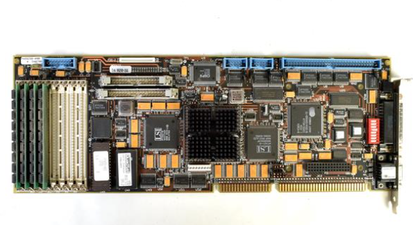
Siemens 7XV5653-0BA00 dual channel binary signal transmitter
Siemens 7XV5653-0BA00 dual channel binary signal transmitter
Overview
The operation manual for Siemens 7XV5653-0BA00 dual channel binary signal transmitter covers all aspects of the equipment from basic information to specific operations. It is suitable for technical personnel who have received professional training and have knowledge in the fields of instrumentation, control, and automatic control engineering, providing guidance for the safe installation, commissioning, operation, and maintenance of the equipment.
Basic Equipment Information
(1) Scope of application and compliance standards
Application scenario interference emission requirements Anti interference requirements
Industrial sector EN 50081-2: 1993 EN 50082-2: 1995
Residential sector (residential, commercial trade, small businesses) EN 50081-1:1992 EN 50082-1:1992
(2) Equipment functions and features
Core function: Dual channel bidirectional binary signal transmitter, capable of converting binary signals with a wide range of inputs. The signal status is serially sent to a similar remote converter through duplex optical fibers. The remote converter outputs the information as command contacts in real time, suitable for switch equipment. It can achieve interference free signal transmission through optical fibers, safely detect misoperations or transmission faults, and send signals through alarm relays.
Performance characteristics:
Two isolated binary inputs, with a wide input voltage range (18V-250VDC) and polarity reversal protection.
Two isolation command relays with large switch capacity.
Point to point connection with short operation time (12-118ms), depending on the data rate.
Fiber optic connection can achieve interference free transmission even in high electromagnetic interference environments.
Protocol communication has monitoring function and transmission security.
Long transmission distance, up to 3km under multimode fiber (62.5/125 μ m), and up to 100km under single-mode fiber when cascaded with 820/1300nm converter 7XV5461-0BA00.
Integrated wide range power supply unit with alarm contacts.
(3) Operation mode
Operation mode, working mode, alarm and signal transmission characteristics
Full duplex mode binary information can be transmitted in both directions simultaneously, such as for direction comparison or signal comparison (according to delivery status). In case of power failure, alarm relay M1 will be released; When no remote converter signal is received, the red LED (ERR) lights up and the alarm relay M1 is released; When running through a modem, if the data connection is interrupted for any reason, to avoid overloading the modem, the device will only send more data after 15 seconds, but will immediately transmit when the binary input signal changes
Half duplex mode binary information is only transmitted unidirectionally through fiber optic cables, requiring only one fiber optic transmitter from the input device to the output device (S2/DIP 7 is set to "transmit only"): in the event of a power failure, alarm relay M1 is released and the transmission link from the transmitter is not monitored;
Receiver (S2/DIP 7 set to "send/receive"): When there is a power failure, the alarm relay is released; When no transmitter signal is received, the fault indicator (red LED: ERR) stays on and the alarm relay M1 is released
(4) General Data and Data Transmission
Auxiliary power supply: Connect DC or AC auxiliary power supply through 2 terminals (N/L-L1/L -), with a wide range of auxiliary power supply (24-250V DC, 60-230V AC), without the need for internal jumper wires, and can be connected to all common substation batteries or AC mains voltage; There is a working voltage LED indicator light (green LED: RUN) on the front of the device, indicating whether the device is operating normally.
Data transmission: The optical interface adopts positive logic (light off in idle state), and the incident light is considered as a valid signal (=1, high level); Built in switch, compatible with negative logic system (fiber optic interface), factory set to positive logic (light off in idle state), and both converters must use the same logic. It is recommended to keep the factory settings.
Fiber optic connection: Fiber optic is connected to the converter through an ST connector.
RS232 interface connection: When connecting to the RS232 interface, it is necessary to disconnect the fiber optic transmission and set the communication to a serial interface; It can be connected to the serial interface of the converter through the serial 7XV5100-4 cable. If other cables are used, the 7th and 8th pins of the bridging cable need to be bridged, and the 1st and 4th pins (X1 of BST) are not assigned.
(5) Binary input
The two binary inputs (BI-1 and BI-2) have a wide input voltage range, with a logic high level "1" of 24V-250V DC (-15%,+20%) and a pickup threshold of 18V. In special cases (such as long-distance unshielded lines and high electrical interference), the threshold can be increased; The logic low level '0' is a voltage level below the threshold.
The corresponding yellow LEDs (BI-1, BI-2) light up when the corresponding binary input is activated (in a logic high state); The LED K1 and K2 display the status of the output contacts, which is set by the binary input in the serial telegram transmitted by the remote converter through fiber optic or RS232 connection (such as a modem with RS232 interface).
- ABB
- General Electric
- EMERSON
- Honeywell
- HIMA
- ALSTOM
- Rolls-Royce
- MOTOROLA
- Rockwell
- Siemens
- Woodward
- YOKOGAWA
- FOXBORO
- KOLLMORGEN
- MOOG
- KB
- YAMAHA
- BENDER
- TEKTRONIX
- Westinghouse
- AMAT
- AB
- XYCOM
- Yaskawa
- B&R
- Schneider
- Kongsberg
- NI
- WATLOW
- ProSoft
- SEW
- ADVANCED
- Reliance
- TRICONEX
- METSO
- MAN
- Advantest
- STUDER
- KONGSBERG
- DANAHER MOTION
- Bently
- Galil
- EATON
- MOLEX
- Triconex
- DEIF
- B&W
- ZYGO
- Aerotech
- DANFOSS
- Beijer
- Moxa
- Rexroth
- Johnson
- WAGO
- TOSHIBA
- BMCM
- SMC
- HITACHI
- HIRSCHMANN
- Application field
- XP POWER
- CTI
- TRICON
- STOBER
- Thinklogical
- Horner Automation
- Meggitt
- Fanuc


