
How to install Johnson AE55/NIE55?
How to install Johnson AE55/NIE55?
Equipment Overview and Application Scenarios
core positioning
NAE (Network Automation Engine) and NIE (Network Integration Engine) are monitoring devices that support web access and are based on Ethernet. Their core functions are to monitor and control on-site building automation equipment, HVAC equipment, and lighting systems. Unless otherwise specified in the document, the MS-NAE55xx-x and MS-NIE55xx-x series are collectively referred to as NAE55.
Emission compliance requirements
United States: Compliant with FCC Part 15 Class A digital device restrictions, only applicable to commercial environments. If interference occurs in residential environments, users need to resolve it themselves.
Canada: Meets the requirements of the Canadian Interference Equipment Regulations (R è glement sur le mat é riel brouilleur du Canada).
Preparation before installation
Package contains components
1 NAE55 host
1 data protection battery (individually packaged)
1 installation manual
Required materials and specialized tools
4 fasteners for compatible mounting surfaces (M4 screws for Europe, # 8 screws for North America)
2 sections of DIN rails 36 centimeters (14 inches) and above (only for DIN rail installation scenarios)
1 small flathead screwdriver (used to fix the communication cable of the terminal block)
Installation environment requirements
Stay away from corrosive gases and follow the environmental restrictions specified in the technical specifications.
Avoid installing on surfaces that are prone to vibration (such as pipelines) or near electromagnetic interference sources (to prevent interference with communication).
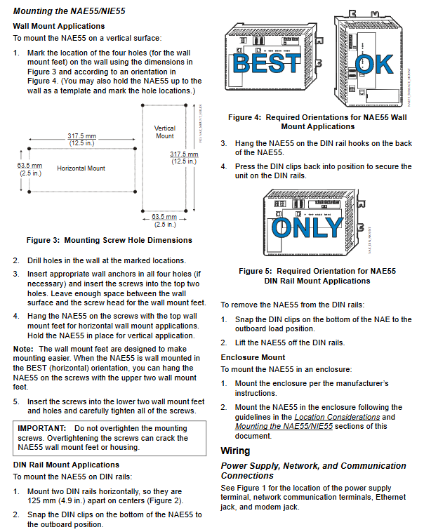
Reserve sufficient space for wiring and terminal connections (refer to size requirements in Figure 2).
The power supply should not be installed below NAE55.
When installing panels/enclosures, it is necessary to avoid sealing the enclosure and ensure that the enclosure walls or transformers do not obstruct the equipment ventilation openings.
Devices that cause the temperature of the NAE55 processor to exceed 77 ° C (171 ° F) must not be added inside the casing (embedded temperature sensor data must be viewed through diagnostic tags).
Installation process
Installation method selection
NAE55 supports three installation methods: wall mounting, DIN rail mounting, and shell mounting. The core operations are as follows:
1. Wall installation (vertical surface)
Mark the four installation hole positions on the wall according to the dimensions in Figure 3 (horizontal installation hole spacing of 317.5mm, vertical installation hole spacing of 63.5mm) or directly using the host as a template.
After drilling, if anchor bolts need to be fixed, they should be inserted into the holes. First, screw the screws into the top two holes, leaving enough space to accommodate the installation feet.
When installing horizontally, hang the top mounting foot of the host on the screw; When installing vertically, the host needs to be held in a fixed position.
Insert the screws into the two holes at the bottom, being careful not to tighten them too tightly (to avoid damaging the mounting feet or housing).
2. DIN rail installation
Install two sections of DIN rails horizontally, with a center to center distance of 125 millimeters (4.9 inches).
Pull the DIN buckle at the bottom of the host to the outer position.
Hang the DIN rail hook on the back of the host onto the rail.
Push the DIN buckle back to its original position and secure the host.
Disassembly steps: First, move the DIN buckle to the outside, and then remove the host from the guide rail.
3. Shell installation
Install the casing according to the manufacturer's instructions.
Following the "Installation Environment Requirements" and the above installation specifications, fix NAE55 inside the casing.
Special installation requirements
The UL 864 certified models (MS-NAE5510-0U and MS-NIE5510-0U) must be installed inside a lockable housing.
Wiring operation
Precautions before wiring
Before wiring, a data protection battery must be installed (see "Settings and Adjustments" section), and a 24VAC power supply must not be connected.
Only copper conductors are used, and wiring must comply with local, national, and regional regulations.
Do not exceed the electrical rating of the equipment (NAE55 is a low-voltage equipment,<30VAC), and do not connect to high voltage (otherwise the equipment will be damaged and the warranty will be invalidated).
The terminal block key must not be removed, and the terminal plug and socket are designed to be foolproof and can only be correctly connected.
Prevent electrostatic discharge (avoid damaging equipment and void warranty).
The power cord and communication cable should be kept at least 50 millimeters (2 inches) away from the ventilation duct on the side of the equipment.
Reserve a certain degree of slack in the cables, and arrange the wiring neatly to ensure ventilation, LED visibility, and maintenance convenience.
Core wiring steps
Ethernet connection: Insert the Ethernet cable into an 8-pin RJ-45 Ethernet port (supporting 10/100 Mbps).
Building Automation System (BAS) Network Connection:
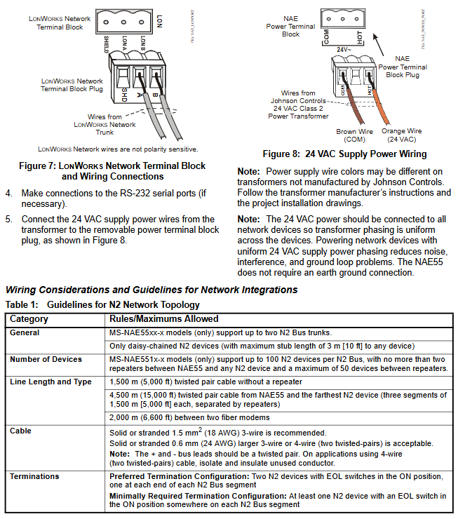
N2 or MS/TP network: Connect three bus lines to a 4-terminal plug labeled FC A or FC B (Figure 6).
LONWorks compatible network: Connect the bus line to a 3-terminal plug (Figure 7), and there is no polarity requirement for the network wiring.
Note: The N2 and BACnet MS/TP bus protocols are different and cannot be connected to the same FC bus port; If connecting to N2 or MS/TP bus, an End of Life (EOL) switch needs to be set up (see "Settings and Adjustments" section).
Modem connection: If needed, connect the phone line to the MODEM port (built-in modem model), or connect an external modem to the USB A port.
RS-232 serial port connection (if required): Use a 9-pin male to male null modem cable to directly connect to a computer, only for point-to-point protocol (PPP) network connection (Serial A port) or obtaining an IP address (Serial B port).
Power connection: Connect the power cord of the 24VAC transformer to the power terminal block (Figure 8) to ensure that the transformer phases of all network devices are consistent (reducing interference and grounding loop issues).
Different network topology wiring specifications
Core limitations and requirements for network types
The N2 network supports 100 devices on a single bus, with a maximum cable length of 1500 meters without repeaters; Recommended 1.5mm ² (18 AWG) 3-core wire,+/- bus must be twisted pair
BACnet MS/TP network supports 100 devices on a single FC bus, with a cable length of 1500 meters without repeaters; Recommended 0.6mm (22 AWG) 3-core shielded twisted pair cable
Ethernet network star topology (requiring network hub/switch), with a maximum of 100 devices connected to a single site
LONWorks network bus topology stub cable with a maximum length of 3 meters; FTT-10 nodes can have a maximum of 64 (without repeaters) or 128 (with repeaters); Install corresponding terminators according to topology type
Settings and Adjustments
Install data protection battery
Remove the battery and open the battery compartment cover on the device (Figure 1).
Connect the connector of the battery cable to the connector inside the battery compartment.
Place the battery in the compartment and secure it with a battery strap (pass through the hole and fasten to reduce movement).
Cover the cabin and immediately connect the 24VAC power supply (to avoid battery depletion and damage).
Attention: The battery can only provide data protection in the event of a power outage after at least 2 hours of initial charging. Full charging (24 hours) can support three consecutive power outages for protection; The battery model is MS-BAT1010-0, with a service life of 3-5 years (at 21 ° C).
Set End Connection (EOL) switch
The devices at both ends of the FC bus section need to be set as network termination devices, and each FC port of NAE55 corresponds to a set of EOL switches:
If NAE55 is an FC bus termination device, set both sets of EOL switches for the corresponding ports to the ON position (default factory ON).
If it is not a terminating device, turn the switch to positions 1 and 2.
Startup and shutdown operations
boot process
Confirm that all wiring is correct and the battery is installed.
Connect the 24VAC power supply, and the device will take up to 5 minutes to start.
Startup completion indicator: The green RUN LED is constantly on, and the red GEN FAULT LED is off.
LED test sequence at startup
After the power is turned on, the PEER COM, RUN, GENL FAULT LEDs (NAE55 also includes FC A, FC B) light up, indicating that the operating system is started.
The above LED is off and the RUN LED is flashing, indicating that the device software is loading.
The LED displays the running status of the device, and if the RUN LED is constantly on, it indicates that the device is ready.
Shutdown process
Disconnect the 24VAC power supply (unplug the power terminal block plug).
The device is powered by a data protection battery and continues to operate for 1-8 minutes (backup volatile data) until the POWER LED goes out.
If the power outage exceeds 48 hours, the data protection battery should be removed after the POWER LED is turned off (to avoid battery depletion and damage).
System restart switch
The System Re Boot switch (Figure 1) can only be pressed when the device is unresponsive and cannot be accessed through the user's device. Restarting will lose the data saved last time (including alarm, trend, and audit tracking data), and other troubleshooting methods should be attempted first.
Troubleshooting
LED status indication (core reference)
Meaning and handling suggestions for abnormal LED names in normal states
POWER (green) constantly on and off indicates that the device is turned off; Always on indicates power supply from battery or 24VAC
ETHENET (green) flashing off indicates no Ethernet traffic, possibly due to network failure or poor connection
FC A/FC B (green) flashing constantly indicates that the port has defined a controller but there is no communication; Extinguish indicates no controller definition (NIE55 does not have this port)
BATT FAULT (red) is off and constantly on, indicating a battery fault (not connected, unable to charge). If it still lights up after 48 hours, check the connection or replace the battery
GENL FAULT (red) off and constantly on indicates general faults (such as high CPU/memory usage, high temperature, battery failure, etc.)
Common problem handling
Battery failure: Check the battery connection. If the connection is normal but still reports an error, replace the MS-BAT1010-0 model battery.
Communication failure: Confirm that the cable connection is correct, the topology meets specifications, the EOL switch setting is correct, and stay away from electromagnetic interference sources.
High temperature: Check the equipment combination inside the casing to ensure that there are no excessive heating devices and good ventilation.
Technical specifications and ordering information
Core technical parameters
Power requirements: Dedicated 24VAC power supply (North American Class 2, European SELV), 50/60Hz, input voltage 20-30VAC
Maximum power consumption of 50 VA
Working environment 0-50 ° C (32-122 ° F), 10-90% RH (dew point ≤ 30 ° C)
Storage environment -40-70 ° C (-40-158 ° F), ≤ 95% RH (dew point ≤ 30 ° C)
Processor MS-NAE5510-0U/NIE5510-0U uses 300MHz Geode GX1; Other models use 400MHz Geode GX533
512MB Flash non-volatile memory, 256MB DRAM
Dimensions (height x width x depth) 226 x 332 x 96.5mm (8.9 x 13.1 x 3.8 inches)
Protection level IP20 (IEC 60529)
Product and accessory ordering
Core product models (partial)
Product code description
MS-NAE5510-1 supports 2 N2 or BACnet MS/TP buses
MS-NAE5510-0U UL 864 8th edition certification, suitable for smoke control
MS-NAE5520-1 supports 1 LONWorks bus and 2 N2/MS/TP buses
MS-NAETUNL-8 N2 Tunnel Function Enabling Tool
Key components
Product code description
MS-BAT1010-0 Data Protection Battery (Replacement)
AS-XFR100-1 24VAC power transformer (with casing)
MS-SECVT-0 Serial to Ethernet Converter (N2 Tunnel Application)
Note: Add "G" after the product code for the US version, "E" for the European version, and "-701" for repair parts.
Maintenance and Compliance Information
Equipment replacement and registration
After replacing the NAE or adding new devices, it is necessary to update the site registration to ensure that the devices are recognized and communicate properly (refer to the NAE Debugging Guide LIT-1201519).
Compliance certification
United States: UL 916 certification, FCC Part 15 Class A, UL 864 smoke control certification (specific models).
Europe: CE mark, compliant with EMC Directive 89/336/EEC.
Australia/New Zealand: C-Tick logo.
International: BACnet BTL 135-2004 certification (B-BC level).
- OMRON
- ABB
- General Electric
- EMERSON
- Honeywell
- HIMA
- ALSTOM
- Rolls-Royce
- MOTOROLA
- Rockwell
- Siemens
- Woodward
- YOKOGAWA
- FOXBORO
- KOLLMORGEN
- MOOG
- KB
- YAMAHA
- BENDER
- TEKTRONIX
- Westinghouse
- AMAT
- AB
- XYCOM
- Yaskawa
- B&R
- Schneider
- KONGSBERG
- NI
- WATLOW
- ProSoft
- SEW
- ADVANCED
- Reliance
- TRICONEX
- METSO
- MAN
- Advantest
- STUDER
- DANAHER MOTION
- Bently
- Galil
- EATON
- MOLEX
- DEIF
- B&W
- ZYGO
- Aerotech
- DANFOSS
- Beijer
- Moxa
- Rexroth
- Johnson
- WAGO
- TOSHIBA
- BMCM
- SMC
- HITACHI
- HIRSCHMANN
- Application field
- XP POWER
- CTI
- TRICON
- STOBER
- Thinklogical
- Horner Automation
- Meggitt
- Fanuc
- Baldor
- SHINKAWA
- Other Brands
- UniOP
- KUKA
- Iba
- Beckhoff
-
 Basler Electric DECS-200-1L Digital Excitation Control System
 -
 Basler DECS125-15-B2C1 Excitation Control
 -
 Basler 9507900205 SSR Retrofit Voltage Regulator
 -
 Basler BE2000E Digital Voltage Regulator
 -
 Basler BE1-GPS Generator Protection System
 -
 Basler DECS-250-CN1CN1N Digital Excitation Control
 -
 Basler DGC-2020 Genset Controller
 -
 Basler BE1-81O UT3ED1LA7N0F Frequency Relay (Variant)
 -
 Basler BE1-81O UT3EE1YA9S0F Frequency Relay (Variant)
 -
 Basler BE1-81O Over/Under Frequency Relay
 -
 Basler DECS125-15 Digital Excitation Control
 -
 Basler Electric BE1-951 Overcurrent Protection System
 -
 Basler Electric BE1-700V Digital Protective Relay
 -
 Basler Electric APR63-5 Automatic Voltage Regulator
 -
 Basler Electric BE1-851 Overcurrent Protection System
 -
 Basler Electric DECS-250-LN1SN1N Excitation Control
 -
 Basler Electric BE1-87T Transformer Differential Relay
 -
 Basler Electric DECS-200-1L Excitation Control System
 -
 Basler Electric 9310300100 DECS-300 Excitation Control
 -
 Basler Electric SSE-N 125-4.5KW Shunt Exciter Regulator
 -
 Basler Electric DGC-2020HD-5NS1DNSBA Genset Controller
 -
Basler Electric BE1-81-O/UT3EE1JB7N1F Frequency Relay
-
 Basler Electric BE1-81T1EE1WA0N1F Frequency Relay
 -
 Basler Electric BE1-25M1EA6PN5R1F Sync-Check Relay
 -
 Basler Electric BE1-GPS Generator Protection System
 -
Basler Electric DECS-250-LN1SN1N Excitation Control Rev V
-
 Basler Electric DECS-250-CN2CN1N Excitation Control
 -
 Basler Electric BE1-50/51B-207 Overcurrent Relay
 -
Basler Electric DECS-300-C0N0 Excitation Control System
-
Basler Electric DECS-200 Digital Excitation Control System
-
Basler Electric DECS-250-LN1CN1N Excitation Unit
-
Basler Electric DECS-250 LN2SA1D Excitation Unit Specs
-
Basler Electric BE1-87T Transformer Relay Review
-
Basler Electric BE1-11 Protection System
-
Basler Electric BE1-GPS100-E4N1H1N Protection System
-
 Allen-Bradley 442G-MABH-R Safety Module
 -
 Beckhoff CX1030-0111 PLC Assembly Profile
 -
 FANUC IC693CPU364 PLC Module
 -
 Orange Denmark Type 200816 220 PLC Specs
 -
 OMRON C200H-SNT31 Sysmac PLC Module
 -
 Allen Bradley 20AB022A3AYNANC0 PowerFlex 70
 -
 OMRON C200HW-PCU01 Position Control Unit
 -
 ABB AO845A-eA Analog Output Module
 -
 OMRON CJ1M-CPU22 CPU Unit
 -
 Allen Bradley 100-E265ED11 Contactor
 -
 Honeywell 51304511-100 Interface Module
 -
 SOLEXY BXF3S0101N0018 Gateway Module
 -
 OMRON CJ2H-CPU65 CPU Unit
 -
 Automation Direct GS2-45P0 AC Drive
 -
 M68-2000 2-Axis Motion CNC Controller
 -
 OMRON CJ1M-CPU11 V3.0 PLC CPU Unit
 -
 OMRON CJ1W-NC413 4-Axis Positioning Controller
 -
 OMRON 3G2A3-PRO16 Programming Console HMI
 -
 Siemens 3VT8440-2AA04-2GA2 Molded Case Circuit Breaker
 -
 Siemens 3RT5045 Contactor Series
 -
 OMRON C200HS-CPU01-E SYSMAC PLC Controller
 -
 OMRON C500-NC103-E Positioning Control Unit
 -
 OMRON CJ1W-TC001 Temperature Control Unit
 -
 OMRON NJ301-1100 NJ-PA3001 PLC System EtherCAT
 -
 Pilz 773100 M1P Safety Relay Base Unit
 -
 Siemens SINUMERIK 840D SL NCU 720.3B with PLC 317-3 PN/DP
 -
 Siemens 6AV6618-7GD01-3AB0 HMI Panel
 -
 OMRON F150-C15E-3 Vision Mate Controller PLC Overview
 -
 Mitsubishi MELSEC A Series PLC System A63P A3ACPU A616AD A68RD3
 -
 M68-2000 2 Axis Motion Controller SCE SERVO CNC
 -
 OMRON FZ-S2M PLC Camera Vision System
 -
 VISOLUX SLVA-4K PLC Module from Elektronik GmbH
 -
 OMRON CJ1M-CPU23 V2.0 PLC CPU Unit
 -
 ABB AI86-16CHF PCB Card 5761751-9 B Specifications
 -
 Allen-Bradley 100-D140ZJ22L Contactor Overview
 -
 Merlin Gerin PB80 PLC Rack
 -
 WEIR WE203 Power Supply PLC
 -
 OMRON NX-TS3102 Temperature Input Unit
 -
 Siemens 6ES7146-6FF00-0AB0 I/O Module
 -
 Fanuc A16B-3300-0057 Circuit Board
 -
 OMRON CJ1W-IDP01 Input Module
 -
 Siemens 6FX2007-1AD13 Handheld Unit
 -
 Gems EM54 PLC Module PCB
 -
 Beckhoff CX2030-0121 Embedded PC CPU
 -
 OMRON NJ301-1100 Machine Automation Controller
 -
 Biesse Rover CNI PLC 2153 030 7146.30 Numerical Control Module
 -
 OMRON CJ1W DA08V Analog Output Module
 -
 OMRON CS1D ETN21D Ethernet Module
 -
 Allen Bradley 1768 L43 CompactLogix Controller
 -
 Schneider TWDLMDA40DTK Twido PLC Module
 -
 Mitsubishi NZ2EX2B 60AD4 Analog Input Module
 -
 OMRON NS8 TV00B V2 Touch Display Panel
 -
 Mitsubishi AY71 CMOS TTL Output Module
 -
 OMRON C500 CPU11 E Processor Module
 -
 OMRON CJ1W PTS51 Temperature Input Module
 -
 Siemens 6SL3100-1DE22-0AA1 600V DC Supply
 -
 OMRON CJ1M-CPU23 PLC CPU 9‑Pin Serial
 -
 Schlumberger IMT4N 24‑250VAC 48‑230VAC PLC Timer
 -
 OMRON CJ1M-CPU22 PLC CPU Unit V2.0
 -
 Allen‑Bradley 2711P-B7C6D2 Touch Screen PanelView
 -
 ADSP-2181KST-160 Analog Devices DSP IC Specs
 -
 Schneider LC1F400 400A Contactor Specifications
 -
 Yaskawa SGDH-10DE-OY 1kW 400V Servo Drive
 -
 Schneider TM262L10MESE8T M262 PLC 5ns Inst
 -
 Mitsubishi AA104VJ05 10.4in LCD Panel Specs
 -
 Allen Bradley 1761-L32BWA MicroLogix 1000 PLC
 -
 Siemens 6ES7431-7KF00-0AB0 Analog Input Module
 -
 Allen Bradley 1769-OB16 Output Module
 -
 Siemens 6ES7131-1BL12-0XB0 Input Module
 -
 Beckhoff EP7041-3002 EtherCAT Box Module
 -
 Siemens RK7243-2AA30-0XB0 Communication Module
 -
 Siemens 4AM5742-8DD40-0FA0 Transformer
 -
 Siemens 3TK2834-1BB40 Safety Relay
 -
 Brother BAS 311 Sewing Machine Circuit Board
 -
Yaskawa SGDH-10DE-OY Servo Driver
-
 OMRON C60H C6DR DE V1 Sysmac PLC
 -
 MITSUBISHI ELECTRIC A2ACPU21 S1 CPU Module
 -
 ABB BAILEY INNPM12 Network Process Module
 -
 HONEYWELL 620 0073C IPC PLC Module
 -
 Mitsubishi 15050 PR02B PLC Circuit Board
 -
 SIEMENS 6SY7000 0AC37 Drive Control Module
 -
 OMRON TJ2 ECT16 Traxial EtherCAT Controller
 -
 GE Fanuc IC698PSD300D Power Supply Module
 -
 Texas Instruments Series 505 16 Position Base
 -
 OMRON YASKAWA SGDH 10DE OY Servo Drive
 -
 Allen‑Bradley 440G-MT Safety Interlock Switch Specs
 -
 Rubycon PD27A 24V 8A Power Supply Module
 -
 SK-H1-GDB1-F11D PLC Gate Driver Board Kit
 -
 VIPA 441-4UA14 451-4UA14 PLC Module Rack
 -
 Mitsubishi FX5U-80MT ESS PLC Controller Specs
 -
 Mitsubishi Q64TCRTN Temperature PLC Module
 -
 GE 1C31170G Rev10 PLC Circuit Board Module
 -
 Schneider TWDLMDA40DTK PLC Controller Module


