
ABB DI581-S Safety digital input module
Power reverse protection: equipped.
Rated protection fuse (fast): 10A.
Current consumed from UP during normal operation: 0.18 A; surge current of 0.1 A when starting a 30 V power supply (lasting for 2 seconds); Surge current of 0.06 A (lasting for 2 seconds) when starting the 24V power supply.
ABB DI581-S Safety digital input module
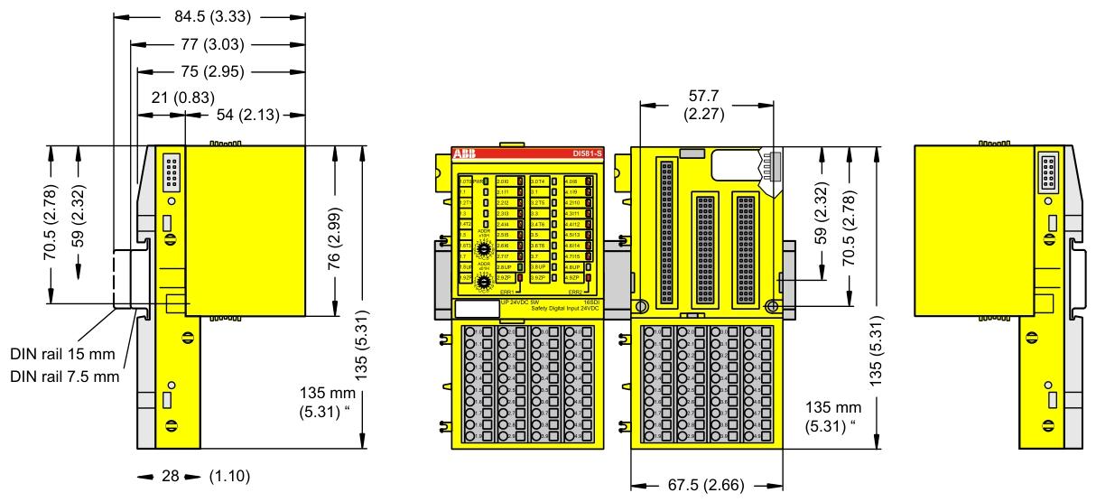
Size and weight
Dimensions: 67.5 x 76 x 62 mm.
Weight: Approximately 130 grams.
Technical Parameter
Power supply
The rated value of the process power supply voltage (UP) is 24 V DC, with an allowable fluctuation range of -15% to+20% and a maximum ripple of 5%.
Power reverse protection: equipped.
Rated protection fuse (fast): 10A.
Current consumed from UP during normal operation: 0.18 A; surge current of 0.1 A when starting a 30 V power supply (lasting for 2 seconds); Surge current of 0.06 A (lasting for 2 seconds) when starting the 24V power supply.
Installation and cooling
Installation position: Horizontal or vertical installation (the maximum working temperature drops to+40 ° C when installed vertically).
Cooling method: Natural convection, cable trays or other components inside the switchgear cabinet must not obstruct cooling.
Allowable values for power interruption (in accordance with EN 61131-2)
DC power interruption:<10 ms.
The time interval between two DC power interruptions (PS2):>1 second.
Environmental condition
Working temperature: 0 ..+60 ° C (DI581-S-XC supports a wider range in special versions).
Storage and transportation temperature: -40 degrees Celsius ...+85 ° C.
Humidity without condensation: maximum 95%.
Working pressure:>800 hPa; Storage pressure:>660 hPa.
Working altitude:<2000 m; Storage altitude:<3500 m.
Mechanical properties
Protection level: IP 20.
The shell complies with UL 94 standard.
Vibration resistance (compliant with EN 61131-2, three-axis): 2 3.5 mm at 15 Hz; 1 g at 15... 150 Hz.
Impact test (three-axis): 11 ms half sine wave 15 g.
Mean Time Between Failures (MTBF): 102 years.
Technical parameters for secure digital input
Number of input channels per module: 16.
Installation and environmental precautions
Environmental adaptation
Ensure that the working environment of the module meets the parameter requirements: temperature (e.g. DI581-S conventional type is 0~+60 ° C, extreme type DI581-S-XC is -40~+70 ° C), humidity (maximum 95% non condensing), altitude (most modules<2000m), avoid corrosive gases, severe vibrations (in accordance with EN 61131-2 standard), and strong electromagnetic interference.
When installing some modules vertically (such as DI581-S), they need to be downgraded (with a maximum temperature of+40 ° C) to ensure that natural convection cooling is not hindered by cable trays or other components.
Mechanical Installation
Installed with 35mm DIN rails (7.5mm or 15mm depth), the tightening torque meets the requirements (such as DI581-S with 1.2 Nm) to avoid loosening and poor contact.
The module protection level is mostly IP20 and needs to be installed in a closed control cabinet to prevent direct contact with dust and liquids.
Precautions for Electrical Connections
Power Supply and Voltage
The power supply must comply with PELV/SELV specifications (such as DI581-S 24V DC power supply fluctuation range -15%~+20%, ripple ≤ 5%), avoid overvoltage (such as DI581-S can withstand up to 30V DC) or reverse connection (most modules have reverse connection protection, but caution is still needed).
When configuring redundant power supplies, ensure that the switching time between the two power supplies is less than 10ms (in accordance with EN 61131-2) to avoid module restarts or data loss.
Wiring specifications
Signal cables and power cables should be wired separately with a spacing of ≥ 10cm. The shielding layer should be grounded at one end to reduce electromagnetic interference (such as the RS-232/485 communication line of CI853, which needs to be shielded).
The terminal wiring of digital input/output modules (such as DI581-S) needs to distinguish between positive and negative signals (UP/ZP) to avoid short circuits (although the module has short circuit protection, it may affect other channels).
Configuration and operation precautions
Software configuration
Use official tools such as Control Builder and Automation Builder to configure and ensure firmware version is compatible with the module (e.g. AC500 CPU firmware updates need to be done through an SD card or tool to avoid firmware damage caused by power outages).
Redundancy configuration (such as module redundancy in CI853) requires enabling corresponding parameters, verifying the normal switching function before putting it into operation.
Protocol and Communication
The communication module (such as CI853 supporting MODBUS RTU, COMLI) needs to match the protocol parameters of the slave device (baud rate, parity check, etc.), and the DriveBus of CI858 needs to pay attention to the bus topology (multiple drives require NDBU branch units).
Hot plugging operations are only performed when the module is supported (such as CI853, CI858). Before plugging, ensure that there are no data transmission peaks to avoid communication interruptions.
Safety and maintenance precautions
Special requirements for security modules
The safety input module (such as DI581-S) needs to perform regular self checks (such as program flow control, RAM/CPU diagnostics) to ensure compliance with SIL certification requirements and prohibit bypassing safety function configurations.
Extreme environment modules (such as DI581-S-XC) need to be derated when the temperature is greater than 60 ° C (such as when the number of activated input channels is ≤ 50%) to avoid overheating damage.
Battery and data backup
CPU modules with batteries (such as AC500) need to be regularly checked for battery level (through function blocks or tools). When the battery level is ≤ 20%, they should be replaced in a timely manner. During replacement, the module should be powered to prevent loss of retention data.
Important data (such as the retain variable) is recommended to be backed up regularly through an SD card (using the pms_ram_deport function block for AC500 v3) to avoid data loss caused by battery failure.
Fault handling
When the module reports an error, priority should be given to checking the LED indicator lights (such as the channel LED of DI581-S and the fault LED of CI853), and troubleshooting wiring, power, or configuration issues should be carried out in conjunction with the manual. Blindly replacing the module is prohibited.
When modules involving safety circuits (such as DI581-S) fail, they need to be shut down according to safety procedures, and after troubleshooting, they can be reset using tools. Forced operation is prohibited.
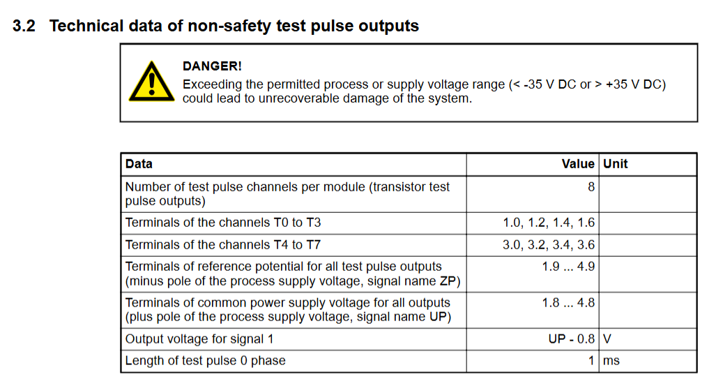
Terminals for channels I0 to I7: 2.0 .. 2.7; Terminals for channels I8 to I15: 4.0 4.7.
All input reference potential terminals (negative pole of process power supply voltage, signal name ZP): 1.9... 4.9.
Electrical isolation from other parts of the module (I/O bus): available.
Input type (compliant with EN 61131-2): Type 1.
Input delay (0 ➔ 1 or 1 ➔ 0): configurable, 1 .. 500 ms。
Input signal indication: Each channel has a yellow LED, and when the input signal is high (signal 1), the LED lights up.
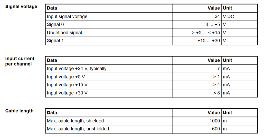
Signal voltage
Input signal voltage: 24 V DC.
Signal 0: -3 .. +5 V。
Undefined signal:>+5 .. < +15 V。
Signal 1:+15 .. +30 V。
Input current per channel
When the input voltage is+24 V: typical 7 mA.
When the input voltage is+5 V:>1 mA.
When the input voltage is+15 V:>4 mA.
When the input voltage is+30 V:<8 mA.
Installation and environmental precautions
Environmental adaptation
Ensure that the working environment of the module meets the parameter requirements: temperature (e.g. DI581-S conventional type is 0~+60 ° C, extreme type DI581-S-XC is -40~+70 ° C), humidity (maximum 95% non condensing), altitude (most modules<2000m), avoid corrosive gases, severe vibrations (in accordance with EN 61131-2 standard), and strong electromagnetic interference.
When installing some modules vertically (such as DI581-S), they need to be downgraded (with a maximum temperature of+40 ° C) to ensure that natural convection cooling is not hindered by cable trays or other components.
Mechanical Installation
Installed with 35mm DIN rails (7.5mm or 15mm depth), the tightening torque meets the requirements (such as DI581-S with 1.2 Nm) to avoid loosening and poor contact.
The module protection level is mostly IP20 and needs to be installed in a closed control cabinet to prevent direct contact with dust and liquids.
Precautions for Electrical Connections
Power Supply and Voltage
The power supply must comply with PELV/SELV specifications (such as DI581-S 24V DC power supply fluctuation range -15%~+20%, ripple ≤ 5%), avoid overvoltage (such as DI581-S can withstand up to 30V DC) or reverse connection (most modules have reverse connection protection, but caution is still needed).
When configuring redundant power supplies, ensure that the switching time between the two power supplies is less than 10ms (in accordance with EN 61131-2) to avoid module restarts or data loss.
Wiring specifications
Signal cables and power cables should be wired separately with a spacing of ≥ 10cm. The shielding layer should be grounded at one end to reduce electromagnetic interference (such as the RS-232/485 communication line of CI853, which needs to be shielded).
The terminal wiring of digital input/output modules (such as DI581-S) needs to distinguish between positive and negative signals (UP/ZP) to avoid short circuits (although the module has short circuit protection, it may affect other channels).
Configuration and operation precautions
Software configuration
Use official tools such as Control Builder and Automation Builder to configure and ensure firmware version is compatible with the module (e.g. AC500 CPU firmware updates need to be done through an SD card or tool to avoid firmware damage caused by power outages).
Redundancy configuration (such as module redundancy in CI853) requires enabling corresponding parameters, verifying the normal switching function before putting it into operation.
Protocol and Communication
The communication module (such as CI853 supporting MODBUS RTU, COMLI) needs to match the protocol parameters of the slave device (baud rate, parity check, etc.), and the DriveBus of CI858 needs to pay attention to the bus topology (multiple drives require NDBU branch units).
Hot plugging operations are only performed when the module is supported (such as CI853, CI858). Before plugging, ensure that there are no data transmission peaks to avoid communication interruptions.
Safety and maintenance precautions
Special requirements for security modules
The safety input module (such as DI581-S) needs to perform regular self checks (such as program flow control, RAM/CPU diagnostics) to ensure compliance with SIL certification requirements and prohibit bypassing safety function configurations.
Extreme environment modules (such as DI581-S-XC) need to be derated when the temperature is greater than 60 ° C (such as when the number of activated input channels is ≤ 50%) to avoid overheating damage.
Battery and data backup
CPU modules with batteries (such as AC500) need to be regularly checked for battery level (through function blocks or tools). When the battery level is ≤ 20%, they should be replaced in a timely manner. During replacement, the module should be powered to prevent loss of retention data.
Important data (such as the retain variable) is recommended to be backed up regularly through an SD card (using the pms_ram_deport function block for AC500 v3) to avoid data loss caused by battery failure.
Fault handling
When the module reports an error, priority should be given to checking the LED indicator lights (such as the channel LED of DI581-S and the fault LED of CI853), and troubleshooting wiring, power, or configuration issues should be carried out in conjunction with the manual. Blindly replacing the module is prohibited.
When modules involving safety circuits (such as DI581-S) fail, they need to be shut down according to safety procedures, and after troubleshooting, they can be reset using tools. Forced operation is prohibited.
- OMRON
- ABB
- General Electric
- EMERSON
- Honeywell
- HIMA
- ALSTOM
- Rolls-Royce
- MOTOROLA
- Rockwell
- Siemens
- Woodward
- YOKOGAWA
- FOXBORO
- KOLLMORGEN
- MOOG
- KB
- YAMAHA
- BENDER
- TEKTRONIX
- Westinghouse
- AMAT
- AB
- XYCOM
- Yaskawa
- B&R
- Schneider
- KONGSBERG
- NI
- WATLOW
- ProSoft
- SEW
- ADVANCED
- Reliance
- TRICONEX
- METSO
- MAN
- Advantest
- STUDER
- DANAHER MOTION
- Bently
- Galil
- EATON
- MOLEX
- DEIF
- B&W
- ZYGO
- Aerotech
- DANFOSS
- Beijer
- Moxa
- Rexroth
- Johnson
- WAGO
- TOSHIBA
- BMCM
- SMC
- HITACHI
- HIRSCHMANN
- Application field
- XP POWER
- CTI
- TRICON
- STOBER
- Thinklogical
- Horner Automation
- Meggitt
- Fanuc
- Baldor
- SHINKAWA
- Other Brands
- UniOP
- KUKA
- Iba
- Beckhoff
-
 Siemens SINUMERIK 840D SL NCU 720.3B with PLC 317-3 PN/DP
 -
 Siemens 6AV6618-7GD01-3AB0 HMI Panel
 -
 OMRON F150-C15E-3 Vision Mate Controller PLC Overview
 -
 Mitsubishi MELSEC A Series PLC System A63P A3ACPU A616AD A68RD3
 -
 M68-2000 2 Axis Motion Controller SCE SERVO CNC
 -
 OMRON FZ-S2M PLC Camera Vision System
 -
 VISOLUX SLVA-4K PLC Module from Elektronik GmbH
 -
 OMRON CJ1M-CPU23 V2.0 PLC CPU Unit
 -
 ABB AI86-16CHF PCB Card 5761751-9 B Specifications
 -
 Allen-Bradley 100-D140ZJ22L Contactor Overview
 -
 Merlin Gerin PB80 PLC Rack
 -
 WEIR WE203 Power Supply PLC
 -
 OMRON NX-TS3102 Temperature Input Unit
 -
 Siemens 6ES7146-6FF00-0AB0 I/O Module
 -
 Fanuc A16B-3300-0057 Circuit Board
 -
 OMRON CJ1W-IDP01 Input Module
 -
 Siemens 6FX2007-1AD13 Handheld Unit
 -
 Gems EM54 PLC Module PCB
 -
 Beckhoff CX2030-0121 Embedded PC CPU
 -
 OMRON NJ301-1100 Machine Automation Controller
 -
 Biesse Rover CNI PLC 2153 030 7146.30 Numerical Control Module
 -
 OMRON CJ1W DA08V Analog Output Module
 -
 OMRON CS1D ETN21D Ethernet Module
 -
 Allen Bradley 1768 L43 CompactLogix Controller
 -
 Schneider TWDLMDA40DTK Twido PLC Module
 -
 Mitsubishi NZ2EX2B 60AD4 Analog Input Module
 -
 OMRON NS8 TV00B V2 Touch Display Panel
 -
 Mitsubishi AY71 CMOS TTL Output Module
 -
 OMRON C500 CPU11 E Processor Module
 -
 OMRON CJ1W PTS51 Temperature Input Module
 -
 Siemens 6SL3100-1DE22-0AA1 600V DC Supply
 -
 OMRON CJ1M-CPU23 PLC CPU 9‑Pin Serial
 -
 Schlumberger IMT4N 24‑250VAC 48‑230VAC PLC Timer
 -
 OMRON CJ1M-CPU22 PLC CPU Unit V2.0
 -
 Allen‑Bradley 2711P-B7C6D2 Touch Screen PanelView
 -
 ADSP-2181KST-160 Analog Devices DSP IC Specs
 -
 Schneider LC1F400 400A Contactor Specifications
 -
 Yaskawa SGDH-10DE-OY 1kW 400V Servo Drive
 -
 Schneider TM262L10MESE8T M262 PLC 5ns Inst
 -
 Mitsubishi AA104VJ05 10.4in LCD Panel Specs
 -
 Allen Bradley 1761-L32BWA MicroLogix 1000 PLC
 -
 Siemens 6ES7431-7KF00-0AB0 Analog Input Module
 -
 Allen Bradley 1769-OB16 Output Module
 -
 Siemens 6ES7131-1BL12-0XB0 Input Module
 -
 Beckhoff EP7041-3002 EtherCAT Box Module
 -
 Siemens RK7243-2AA30-0XB0 Communication Module
 -
 Siemens 4AM5742-8DD40-0FA0 Transformer
 -
 Siemens 3TK2834-1BB40 Safety Relay
 -
 Brother BAS 311 Sewing Machine Circuit Board
 -
Yaskawa SGDH-10DE-OY Servo Driver
-
 OMRON C60H C6DR DE V1 Sysmac PLC
 -
 MITSUBISHI ELECTRIC A2ACPU21 S1 CPU Module
 -
 ABB BAILEY INNPM12 Network Process Module
 -
 HONEYWELL 620 0073C IPC PLC Module
 -
 Mitsubishi 15050 PR02B PLC Circuit Board
 -
 SIEMENS 6SY7000 0AC37 Drive Control Module
 -
 OMRON TJ2 ECT16 Traxial EtherCAT Controller
 -
 GE Fanuc IC698PSD300D Power Supply Module
 -
 Texas Instruments Series 505 16 Position Base
 -
 OMRON YASKAWA SGDH 10DE OY Servo Drive
 -
 Allen‑Bradley 440G-MT Safety Interlock Switch Specs
 -
 Rubycon PD27A 24V 8A Power Supply Module
 -
 SK-H1-GDB1-F11D PLC Gate Driver Board Kit
 -
 VIPA 441-4UA14 451-4UA14 PLC Module Rack
 -
 Mitsubishi FX5U-80MT ESS PLC Controller Specs
 -
 Mitsubishi Q64TCRTN Temperature PLC Module
 -
 GE 1C31170G Rev10 PLC Circuit Board Module
 -
 Schneider TWDLMDA40DTK PLC Controller Module
 -
 Omron FQM1-MMA22 Motion Control Module Specs
 -
 OMRON CJ1W-NCF71 Position Control Unit Specs
 -
 Schneider TSXETY4103 Ethernet Module
 -
 Mitsubishi Q12PHCPU Process CPU
 -
 Yaskawa 3G3HV-A4022-CE AC Drive
 -
 Cincinnati Milacron 3-533-0669G Temperature Control Board
 -
 Allen Bradley 20AC030A3AYNANC0 PowerFlex 70 Drive
 -
 Siemens 6ES7314-6BG03-0AB0 CPU 314C-2 DP
 -
 Carrier 17EX54007903 PLC Module
 -
 OMRON CS1W-V600C12 ID Controller Module
 -
 Honeywell 51402755-100 PCB Card
 -
 Heidenhain ECN 113 Rotary Encoder
 -
 OMRON B7AM-8B16 I/O Terminal Block
 -
 Fanuc A06B-6110-H026 Power Supply Module
 -
 Schneider TSXETG3021 Ethernet Gateway
 -
 OMRON CS1W-CLK21-V1 Controller Link Unit
 -
 NP1W6406T-Z704 PLC I/O Module
 -
 OMRON CJ1W-DA08C Analog Output Module
 -
 Yaskawa 3G3HV-A4022-CE AC Drive
 -
 OMRON NB7W-TW01B CP1L-EL20DR-D Power Panel
 -
 OMRON C500-NC103-E Position Control Unit
 -
 Steag Hamatech PLC DCS Servo Control System
 -
 Siemens 6SN1123-1AA00-0DA1 Power Supply Module
 -
 GE IC693CHS391H CPU & AD693CMM301A PLC Module
 -
 Siemens 6FC5303-0AF23-1AA1 PLC Control Panel
 -
 Square D CM4000T PowerLogic Circuit Monitor J1 F16
 -
 Siemens 6FX5002-5DG10-1BA0 MOTION-CONNECT 500 Cable
 -
 Schmersal SRB324ST 101195504 Safety Relay 24V
 -
 Mitsubishi 15050-PR02A PLC Circuit Board Module
 -
 OMRON CQM1-AD041 Analog Input PLC Module
 -
 Beckhoff EL5042 EtherCAT PLC Terminal Module
 -
 OMRON C200HW-MC402-E Motion Control Unit
 -
 C36TC0UA1100 Industrial Temperature Controller
 -
 NL8048BC24 12 Industrial Control LCD Module
 -
 OMRON R88D Servo Drive and Motor System
 -
 OMRON CS1W CLK21 V1 Controller Link Module
 -
 OMRON YASKAWA R7M A20030 S1 D Servo Motor
 -
 SIEMENS 6AV2128 3KB06 0AX1 Unified Comfort Panel
 -
 Schneider Electric METSEPM8240 PowerLogic Meter
 -
 Advanced AMCI 1PLC 1 31F Programmable Limit Switch
 -
 ABB PM582 ETH Programmable Logic Processor
 -
 SIEMENS 6FC5110 0CB01 0AA0 CPU Control Board
 -
 Schleicher P03GS13A CPU Module
 -
 Siemens 6SN1123-1AA00-0BA1 Power Module
 -
 Mitsubishi A1S61PN Power Supply Module
 -
 Yaskawa CPS-IONB DC Power Supply Module
 -
 Siemens 6ES7215-2BD00 CPU 215-2
 -
 Mitsubishi A2ACPU MELSEC PLC System Kit
 -
 ProSoft 3150-MCM Communication Module
 -
 Mitsubishi OSE104ET Incremental Encoder
 -
 OMRON CJ1W-AD081-V1 Analog Input Module
 -
 Broadcom BCM5464A1KRB Quad Port Ethernet IC
 -
 Modicon M221-24IO TM221C24 PLC 24 PNP Transistor
 -
 Allen-Bradley 1321-3R160-B Line Reactor 3R160B
 -
 Beckhoff CX1020-0012 Embedded PLC Module Specs
 -
 Turck BL20-PF-24VDC-D Power Feed Module Specs
 -
 Siemens 6SY7000-0AC37 Power Supply Module
 -
 Yaskawa SGDH-10DE-OY 1kW 400V Servo Drive Specs
 -
 Omron 3G3SV-BB015-E 1.5kW 220V VFD Specs
 -
 Uni-Pro CPU91-PLC J 23.020167X Processor Module


