
Emerson DeltaV ™ Electronic Marshalling for Migrations
Emerson DeltaV ™ Electronic Marshalling for Migrations
Core positioning and core advantages
The electronic grouping for DeltaV migration is built on CHARM I/O cards (CIOC) and designed specifically for the migration of traditional control systems to DeltaV systems. With "high flexibility, low transformation cost, and full redundancy and reliability" as the core, it achieves in-situ replacement and efficient integration of I/O modules. The core advantages can be summarized as six key features:
Flexible deployment of I/O: CIOC supports 1:1 direct replacement within the same space as traditional I/O, without the need for new cabinets, customized cables, or additional grouping; I/O can be installed in any adaptive position of the existing cabinet as needed, adapting to the layout requirements of different migration scenarios.
Single channel refined configuration: The CHARM I/O architecture supports independent adaptation of field device requirements for each channel. Any instrument signal can be connected to any terminal block, and electronic grouping can be completed by installing the corresponding CHARM module and assigning it to up to 4 controllers; No need to split traditional panel signals into multiple DeltaV I/O cards, solving the problem of adapting traditional I/O terminals.
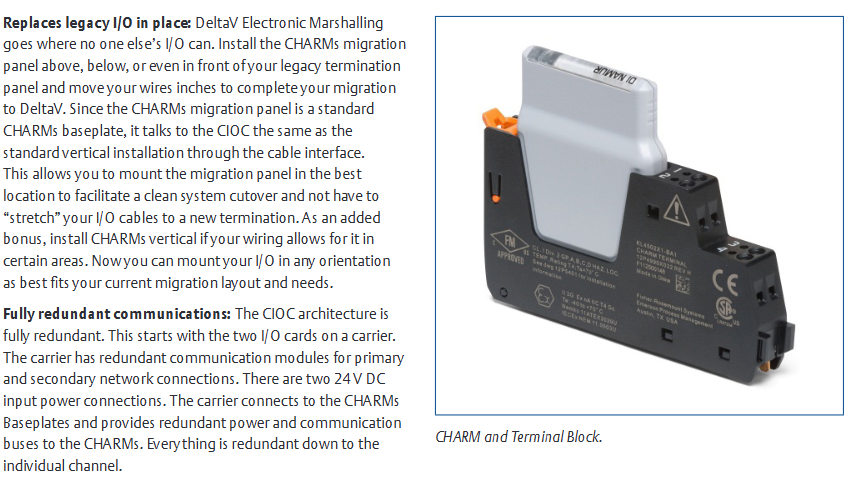
In situ replacement of traditional I/O: The migration panel can be installed above, below, or even in front of the traditional terminal panel, and the migration can be completed by simply moving the wires a few inches; As a standard CHARM motherboard, the migration panel communicates with CIOC through cable interfaces and is suitable for vertical or horizontal installation (supported in some scenarios), without the need to stretch I/O cables, ensuring smooth system switching.
Fully redundant communication architecture: Full link redundancy from the CHARM channel to the DeltaV controller, including dual I/O cards on the carrier, redundant communication modules (primary/backup network connections), dual 24V DC input power supplies, and redundant power and communication buses provided by the carrier to the CHARM backplane, ensuring high system reliability.
Complete DeltaV solution: After migration, the system is built entirely on DeltaV standard hardware, without mixed custom software and hardware. It can be supported by existing DeltaV operation and maintenance personnel using unified spare parts, reducing maintenance complexity and costs in the later stage.
Plug and play I/O: At the hardware level, components are quickly assembled through DIN rail locks and interlocking carrier connectors; At the software level, after inserting CHARM, the system automatically recognizes the node and generates I/O definitions in the configuration database. The CHARM self key control system avoids accidental insertion; Support drag and drop operations to assign any number of channels to the controller, simplifying the configuration process.
Core components and functional details of the product
(1) Core hardware components
CHARM I/O carrier DIN rail installation, supports redundant CHARM I/O card pairs, provides redundant communication modules and dual 24V DC power interfaces, connects to CHARM motherboard and transmits redundant power/communication bus
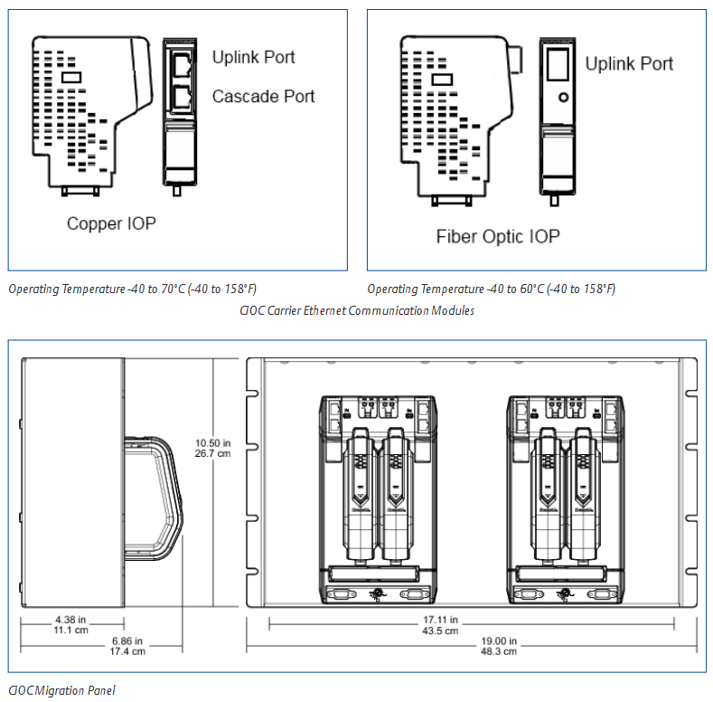
CHARM I/O cards (CIOC/CIOC2) achieve communication between CHARM and Ethernet I/O networks (connecting M/S/PK series controllers). CIOC has obtained Achilles communication certification level 1; CIOC2 has stronger computing power and has obtained certification level 2, which can directly replace CIOC
CHARM base plate DIN rail installation, including interleaved power and bus connectors supporting 12 CHARMs and terminal blocks, providing on-site injection power interface, compatible with migration panel installation
CHARM terminal block can be disassembled, connected to on-site wiring and fixed. CHARM supports 2/3/4 wire system equipment wiring, and some models include fused injection power function
The CHARM module (Characterization Module) provides basic analog-to-digital conversion, redundant bus connection, and fault isolation for each field signal. It has circuit protection functions (current limiting/melting) and surge protection (in accordance with EMC industry standards), and faults are limited to a single module
Other auxiliary components include cable extenders (flexible adjustment of carrier installation position), backplane terminators (redundant I/O bus terminals), and 19 inch migration panels (compatible with traditional 19 inch cabinets, supporting 2 CIOC or 2 backplane installations) to ensure hardware installation flexibility and bus signal stability
(2) Key functional characteristics
Power supply: On site power is supplied to each CHARM (maximum 100mA per module) through a redundant 24V DC bus; The high current discrete channel can be powered by injecting the bus through the locally integrated power supply on the motherboard.
Maintenance convenience: CHARM can partially pop up to the locked position, disconnect the on-site wiring from the system, and facilitate on-site maintenance or cutting off equipment power; Activate the lock buckle to eject to the positioning position, and close the lock buckle to isolate the on-site wiring.
System scalability: CIOC can connect up to 4 controllers via Ethernet, and adding controllers or reallocating I/O does not require any physical wiring changes; Support online addition of CHARM (any empty space on the motherboard) and CIOC to adapt to changes in I/O requirements during the migration process.
Installation flexibility: CIOC needs to be installed on vertical DIN rails (which can be located on the front and rear sides, upper and lower parts of the cabinet), and cannot be installed horizontally; The height of the CHARM base plate migration component is 3 EIA units (5.25 inches), and the installation location can be flexibly selected (reusing existing cable trays/cable trays, adjacent installation, or reserved spacing).
Hardware specifications and compatibility
(1) Core hardware environment and size specifications
1. CHARM I/O Migration Panel
Environmental specifications working temperature: -40~70 ° C (copper Ethernet port), -40~60 ° C (fiber Ethernet port); Storage temperature: -40~85 ° C; relative humidity: 5%~95% (no condensation); Protection level: IP20; Pollutant level: ISA-S71.04-1985 G3 level (with conformal coating); Impact resistance: 10g half sine wave (continuous for 11ms); Vibration: 5-13.2Hz (1mm peak to peak), 13.2-150Hz (0.7g)
Dimensions: Height 10.5 inches (26.7cm), Depth 6.68 inches (17.4cm), Width 19 inches (48.3cm); Installation method: 19 inch EIA rail (6 rack units high)
2. CHARM Bottom Plate Migration Panel
The environmental specifications are consistent with the CHARM I/O migration panel (with a fixed operating temperature of -40~70 ° C)
Dimensions: Height 5.25 inches (13.3cm), Depth 4.8 inches (12.2cm), Width 19 inches (48.3cm); Installation method: 19 inch EIA rail (3 rack units high)
3. IS CHARM Bottom Plate Migration Panel
The environmental specifications are consistent with the above-mentioned bottom migration panel
Size without channel identification label: Height 5.34 inches (13.6cm), Depth 6.45 inches (16.4cm); Channel identification label: height 5.73 inches (14.6cm), depth 6.45 inches (16.4cm); The width is 19 inches (48.3cm), and the installation method is the same as before (3 rack units high)
Special note: The size of IS CHARM is different from non IS models. When installed on a 19 inch panel, it protrudes 45mm from non IS models
(2) System compatibility
Software version requirements: DeltaV electronic grouping hardware must be paired with DeltaV v11.3.1 or higher versions.
Controller adaptation: Supports M-series, S-series, and PK series controllers.
Component compatibility: All CHARM types, IS/non IS I/O terminal blocks, and key control columns are compatible with the migration panel; CIOC2 can directly replace CIOC, and the fiber optic Ethernet I/O ports cannot be cascaded.

Ordering Information and Preconditions
(1) Core Hardware Ordering List (Some Key Models)
CHARM I/O card redundant migration CIOC2 (copper Ethernet), including redundant CIOC2, carrier with screw terminals, copper I/O ports, etc. SE6505T03
CHARM I/O card redundant migration CIOC2 (fiber optic Ethernet), including redundant CIOC2, carrier with screw terminals, fiber optic I/O ports, etc. SE6505T04
Migration panel 19 inch migration panel, supporting 2 redundant migration CIOC SE6503T01
CHARM Base Plate Component Standard Migration Base Plate Component (2 Base Plates, 24 Standard Terminal Blocks, etc.) SE4601T03
CHARM motherboard component with 3-wire DI fuse injection power supply migration motherboard component SE4601T10
CHARM Base Plate Component with Relay Output Migration Base Plate Component SE4601T06
IS CHARM Base Plate IS CHARM Migration Base Plate Component (2 IS Base Plates, 24 IS Standard Terminal Blocks, etc.) SE4608T02
Address plug CHARM Address plug (1-8) SE4602
Address plug CHARM Address plug (1-4) SE4613
Auxiliary component CHARM baseplate top extender (with plug) SE4603T05
Auxiliary component CHARM base plate bottom extender (with socket) SE4603T06
Auxiliary component CHARM base cable (2 pieces, 0.5m) SE4605T02
Auxiliary component DIN rail block (5 pieces/box) VE4054DRS
IS special accessory IS CHARM 24V DC power fuse component SE4610T01 (to be ordered in combination with SE6501T03/SE6501T04 for 2 units)
(2) Pre requirements
Hardware installation must follow DIN rail specifications, and vertical DIN rails must be equipped with a stopper (model VE4054DRS) to fix the position of the base plate.
When using the IS CHARM motherboard, an additional order for SE4610T01 fuse components is required (2 for each CIOC configuration compatible with the IS motherboard).
Fiber optic Ethernet I/O ports cannot be cascaded, and attention should be paid to network topology design.
- OMRON
- ABB
- General Electric
- EMERSON
- Honeywell
- HIMA
- ALSTOM
- Rolls-Royce
- MOTOROLA
- Rockwell
- Siemens
- Woodward
- YOKOGAWA
- FOXBORO
- KOLLMORGEN
- MOOG
- KB
- YAMAHA
- BENDER
- TEKTRONIX
- Westinghouse
- AMAT
- AB
- XYCOM
- Yaskawa
- B&R
- Schneider
- KONGSBERG
- NI
- WATLOW
- ProSoft
- SEW
- ADVANCED
- Reliance
- TRICONEX
- METSO
- MAN
- Advantest
- STUDER
- DANAHER MOTION
- Bently
- Galil
- EATON
- MOLEX
- DEIF
- B&W
- ZYGO
- Aerotech
- DANFOSS
- Beijer
- Moxa
- Rexroth
- Johnson
- WAGO
- TOSHIBA
- BMCM
- SMC
- HITACHI
- HIRSCHMANN
- Application field
- XP POWER
- CTI
- TRICON
- STOBER
- Thinklogical
- Horner Automation
- Meggitt
- Fanuc
- Baldor
- SHINKAWA
- Other Brands
- UniOP
- KUKA
- Iba
- Beckhoff
-
 Siemens SINUMERIK 840D SL NCU 720.3B with PLC 317-3 PN/DP
 -
 Siemens 6AV6618-7GD01-3AB0 HMI Panel
 -
 OMRON F150-C15E-3 Vision Mate Controller PLC Overview
 -
 Mitsubishi MELSEC A Series PLC System A63P A3ACPU A616AD A68RD3
 -
 M68-2000 2 Axis Motion Controller SCE SERVO CNC
 -
 OMRON FZ-S2M PLC Camera Vision System
 -
 VISOLUX SLVA-4K PLC Module from Elektronik GmbH
 -
 OMRON CJ1M-CPU23 V2.0 PLC CPU Unit
 -
 ABB AI86-16CHF PCB Card 5761751-9 B Specifications
 -
 Allen-Bradley 100-D140ZJ22L Contactor Overview
 -
 Merlin Gerin PB80 PLC Rack
 -
 WEIR WE203 Power Supply PLC
 -
 OMRON NX-TS3102 Temperature Input Unit
 -
 Siemens 6ES7146-6FF00-0AB0 I/O Module
 -
 Fanuc A16B-3300-0057 Circuit Board
 -
 OMRON CJ1W-IDP01 Input Module
 -
 Siemens 6FX2007-1AD13 Handheld Unit
 -
 Gems EM54 PLC Module PCB
 -
 Beckhoff CX2030-0121 Embedded PC CPU
 -
 OMRON NJ301-1100 Machine Automation Controller
 -
 Biesse Rover CNI PLC 2153 030 7146.30 Numerical Control Module
 -
 OMRON CJ1W DA08V Analog Output Module
 -
 OMRON CS1D ETN21D Ethernet Module
 -
 Allen Bradley 1768 L43 CompactLogix Controller
 -
 Schneider TWDLMDA40DTK Twido PLC Module
 -
 Mitsubishi NZ2EX2B 60AD4 Analog Input Module
 -
 OMRON NS8 TV00B V2 Touch Display Panel
 -
 Mitsubishi AY71 CMOS TTL Output Module
 -
 OMRON C500 CPU11 E Processor Module
 -
 OMRON CJ1W PTS51 Temperature Input Module
 -
 Siemens 6SL3100-1DE22-0AA1 600V DC Supply
 -
 OMRON CJ1M-CPU23 PLC CPU 9‑Pin Serial
 -
 Schlumberger IMT4N 24‑250VAC 48‑230VAC PLC Timer
 -
 OMRON CJ1M-CPU22 PLC CPU Unit V2.0
 -
 Allen‑Bradley 2711P-B7C6D2 Touch Screen PanelView
 -
 ADSP-2181KST-160 Analog Devices DSP IC Specs
 -
 Schneider LC1F400 400A Contactor Specifications
 -
 Yaskawa SGDH-10DE-OY 1kW 400V Servo Drive
 -
 Schneider TM262L10MESE8T M262 PLC 5ns Inst
 -
 Mitsubishi AA104VJ05 10.4in LCD Panel Specs
 -
 Allen Bradley 1761-L32BWA MicroLogix 1000 PLC
 -
 Siemens 6ES7431-7KF00-0AB0 Analog Input Module
 -
 Allen Bradley 1769-OB16 Output Module
 -
 Siemens 6ES7131-1BL12-0XB0 Input Module
 -
 Beckhoff EP7041-3002 EtherCAT Box Module
 -
 Siemens RK7243-2AA30-0XB0 Communication Module
 -
 Siemens 4AM5742-8DD40-0FA0 Transformer
 -
 Siemens 3TK2834-1BB40 Safety Relay
 -
 Brother BAS 311 Sewing Machine Circuit Board
 -
Yaskawa SGDH-10DE-OY Servo Driver
-
 OMRON C60H C6DR DE V1 Sysmac PLC
 -
 MITSUBISHI ELECTRIC A2ACPU21 S1 CPU Module
 -
 ABB BAILEY INNPM12 Network Process Module
 -
 HONEYWELL 620 0073C IPC PLC Module
 -
 Mitsubishi 15050 PR02B PLC Circuit Board
 -
 SIEMENS 6SY7000 0AC37 Drive Control Module
 -
 OMRON TJ2 ECT16 Traxial EtherCAT Controller
 -
 GE Fanuc IC698PSD300D Power Supply Module
 -
 Texas Instruments Series 505 16 Position Base
 -
 OMRON YASKAWA SGDH 10DE OY Servo Drive
 -
 Allen‑Bradley 440G-MT Safety Interlock Switch Specs
 -
 Rubycon PD27A 24V 8A Power Supply Module
 -
 SK-H1-GDB1-F11D PLC Gate Driver Board Kit
 -
 VIPA 441-4UA14 451-4UA14 PLC Module Rack
 -
 Mitsubishi FX5U-80MT ESS PLC Controller Specs
 -
 Mitsubishi Q64TCRTN Temperature PLC Module
 -
 GE 1C31170G Rev10 PLC Circuit Board Module
 -
 Schneider TWDLMDA40DTK PLC Controller Module
 -
 Omron FQM1-MMA22 Motion Control Module Specs
 -
 OMRON CJ1W-NCF71 Position Control Unit Specs
 -
 Schneider TSXETY4103 Ethernet Module
 -
 Mitsubishi Q12PHCPU Process CPU
 -
 Yaskawa 3G3HV-A4022-CE AC Drive
 -
 Cincinnati Milacron 3-533-0669G Temperature Control Board
 -
 Allen Bradley 20AC030A3AYNANC0 PowerFlex 70 Drive
 -
 Siemens 6ES7314-6BG03-0AB0 CPU 314C-2 DP
 -
 Carrier 17EX54007903 PLC Module
 -
 OMRON CS1W-V600C12 ID Controller Module
 -
 Honeywell 51402755-100 PCB Card
 -
 Heidenhain ECN 113 Rotary Encoder
 -
 OMRON B7AM-8B16 I/O Terminal Block
 -
 Fanuc A06B-6110-H026 Power Supply Module
 -
 Schneider TSXETG3021 Ethernet Gateway
 -
 OMRON CS1W-CLK21-V1 Controller Link Unit
 -
 NP1W6406T-Z704 PLC I/O Module
 -
 OMRON CJ1W-DA08C Analog Output Module
 -
 Yaskawa 3G3HV-A4022-CE AC Drive
 -
 OMRON NB7W-TW01B CP1L-EL20DR-D Power Panel
 -
 OMRON C500-NC103-E Position Control Unit
 -
 Steag Hamatech PLC DCS Servo Control System
 -
 Siemens 6SN1123-1AA00-0DA1 Power Supply Module
 -
 GE IC693CHS391H CPU & AD693CMM301A PLC Module
 -
 Siemens 6FC5303-0AF23-1AA1 PLC Control Panel
 -
 Square D CM4000T PowerLogic Circuit Monitor J1 F16
 -
 Siemens 6FX5002-5DG10-1BA0 MOTION-CONNECT 500 Cable
 -
 Schmersal SRB324ST 101195504 Safety Relay 24V
 -
 Mitsubishi 15050-PR02A PLC Circuit Board Module
 -
 OMRON CQM1-AD041 Analog Input PLC Module
 -
 Beckhoff EL5042 EtherCAT PLC Terminal Module
 -
 OMRON C200HW-MC402-E Motion Control Unit
 -
 C36TC0UA1100 Industrial Temperature Controller
 -
 NL8048BC24 12 Industrial Control LCD Module
 -
 OMRON R88D Servo Drive and Motor System
 -
 OMRON CS1W CLK21 V1 Controller Link Module
 -
 OMRON YASKAWA R7M A20030 S1 D Servo Motor
 -
 SIEMENS 6AV2128 3KB06 0AX1 Unified Comfort Panel
 -
 Schneider Electric METSEPM8240 PowerLogic Meter
 -
 Advanced AMCI 1PLC 1 31F Programmable Limit Switch
 -
 ABB PM582 ETH Programmable Logic Processor
 -
 SIEMENS 6FC5110 0CB01 0AA0 CPU Control Board
 -
 Schleicher P03GS13A CPU Module
 -
 Siemens 6SN1123-1AA00-0BA1 Power Module
 -
 Mitsubishi A1S61PN Power Supply Module
 -
 Yaskawa CPS-IONB DC Power Supply Module
 -
 Siemens 6ES7215-2BD00 CPU 215-2
 -
 Mitsubishi A2ACPU MELSEC PLC System Kit
 -
 ProSoft 3150-MCM Communication Module
 -
 Mitsubishi OSE104ET Incremental Encoder
 -
 OMRON CJ1W-AD081-V1 Analog Input Module
 -
 Broadcom BCM5464A1KRB Quad Port Ethernet IC
 -
 Modicon M221-24IO TM221C24 PLC 24 PNP Transistor
 -
 Allen-Bradley 1321-3R160-B Line Reactor 3R160B
 -
 Beckhoff CX1020-0012 Embedded PLC Module Specs
 -
 Turck BL20-PF-24VDC-D Power Feed Module Specs
 -
 Siemens 6SY7000-0AC37 Power Supply Module
 -
 Yaskawa SGDH-10DE-OY 1kW 400V Servo Drive Specs
 -
 Omron 3G3SV-BB015-E 1.5kW 220V VFD Specs
 -
 Uni-Pro CPU91-PLC J 23.020167X Processor Module


