
Bender EDS3090/-91/-92/-96 series
Please observe the limits on the area of application stated in the technical specifications, as well as the measuring categories for the measuring clamps used. If, in the specific case, measuring current transformers other than the measuring clamps supplied are used with the EDS195P(M), adequate nominal insulation voltage must be ensured for the connection wires and transformer (overvoltage category, see Technical data).
Do not make any unauthorised changes to the device. Only use spare parts and optional accessories sold or recommended by the manufacturer.
Any other use than that described in this manual is regarded as improper.
Bender EDS3090/-91/-92/-96 series
Intended use
The portable insulation fault location system EDS309… is used to locate insulation faults in IT systems. All variants are suitable for the measurement of residual currents in TN and TT systems. The EDS3096PG is particularly suitable for insulation fault location in electrically isolated systems.
Please observe the limits on the area of application stated in the technical specifications, as well as the measuring categories for the measuring clamps used. If, in the specific case, measuring current transformers other than the measuring clamps supplied are used with the EDS195P(M), adequate nominal insulation voltage must be ensured for the connection wires and transformer (overvoltage category, see Technical data).
Do not make any unauthorised changes to the device. Only use spare parts and optional accessories sold or recommended by the manufacturer.
Any other use than that described in this manual is regarded as improper.
Device features
Portable insulation fault location systems for IT systems AC 0…790 V, 42…460 Hz/DC 0…960 V or deenergised systems
Residual current measurement in TN/TT systems
Use in main and control circuits, photovoltaic systems
Measuring clamps 20/52 mm (115 mm optional)
Robust aluminium case, convenient to carry
Locating current injectors PGH18… with variable locating current 1…25 mA
Integrated locating voltage for deenergised systems (PGH186)
Insulation fault EDS195P(M)
Backlit LC display, 3 x 16 characters
Measuring clamps 20/52 mm included in the scope of delivery
Accumulator (delivered with a power supply unit)
Response value insulation fault location 2…10 mA for main circuits
Response value insulation fault location 0.2…1 mA for control circuits
Response value residual current measurement 10 mA…10 A
Selectable operating mode insulation fault location/residual current measurement

Function of the system components
The following system components are required for correct operation:
Locating current injector PGH18…
The PGH18… generates a defined locating current. The current depends on the insulation fault and the system voltage.
The PGH185 or PGH186 limits the locating current to maximum 25 mA or maximum 10 mA depending on the switch setting.
The PGH183 limits the locating current to maximum 2.5 mA or maximum 1 mA depending on the switch setting.
The PGH186 applies the locating current in electrically isolated IT systems or in IT systems with a system (voltage <50 ~V) using an integrated voltage source (DC 50 V).In
IT systems with a system voltage > 50 V the existing voltage in the system is used to drive the locating current.
Insulation fault locator EDS195P(M)
Insulation fault location (I_{Delta L}) (EDS mode) for use in IT AC or DC systems:
Either as a component of the portable equipment for insulation fault location EDS309…
Or as an additional insulation fault locator in permanently installed equipment for insulation fault location with IRDH575, iso685-x-P or isoxx1685xP or PGH1… as well as EDS4…
EDS195PM - only devices with the suffix "M" have the measuring signal output for connecting an oscilloscope
Residual current measurement (lior) (mode) for usage in TN or TT AC systems.
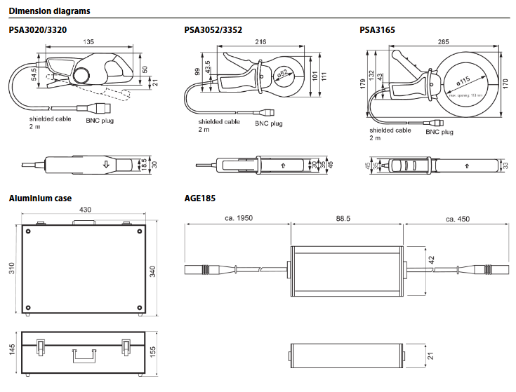
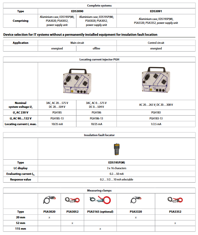
Measuring clamps
Measuring clamps measure the locating current or the residual current. They have a test lead approx. 2 m long. They are connected to the EDS195P(M) via a BNC connector.
If measuring current transformers are used instead of measuring clamps, you will need the adapter supplied: BNC/4-mm connector. See “Component list”, page 14.
Coupling device AGE185
The coupling device AGE185 expands the nominal voltage range of the equipment for insulation fault location EDS309…. It enables the equipment to be connected to system nominal voltages up to AC 790 V or DC 960 V.
Residual current measurement is possible in TT and TN systems (earthed systems) using the device variants listed below. The following overview describes which tasks can be done with which models.
Equipment for insulation fault location in main circuits
1. Permissible system voltage in the main circuits:
Insulation fault location in IT systems up to AC 42…460 Hz, 20…575 V and DC 20…504 V
Insulation fault location using AGE185 up to AC 42…460 Hz, 500…790 V and DC 400…960 V
EDS3090:
Can be used in IT systems in which a locating current injector (e.g. PGH471) or an ISOMETER® with integrated locating current injector (e.g. iso685-x-P) is already installed.
EDS3090PG:
Can be used in IT systems in which no locating current generator and no ISOMETER® with integrated locating current generator is installed.
Supply voltage for the locating current generator PGH185 supplied: AC 50…60 Hz, 230 V
EDS3090PG-13:
• Can be used in IT systems in which no locating current generator and no ISOMETER® with integrated locating current generator is installed.
Supply voltage for the locating current generator PGH185-13 supplied: AC 50…60 Hz, 90…132 V
2. Permissible system voltage in the main circuits:
Insulation fault location in IT systems up to AC 42…460 Hz, 0…575 V and DC 0…504 V
Insulation fault location using AGE185 up to AC 42…460 Hz, 500…790 V and DC 400…960 V
EDS3096PG:
Can be used in IT systems in which no locating current generator and no ISOMETER® with integrated locating current generator is installed.
Supply voltage for the locating current generator PGH186 supplied: AC 50…60 Hz, 230 V
Insulation fault location, also in IT systems electrically isolated on all poles
EDS3096PG-13:
Can be used in IT systems in which no locating current generator and no ISOMETER® with integrated locating current generator is installed.
Supply voltage for the locating current generator PGH186-13 supplied: AC 50…60 Hz, 90…132 V
Insulation fault location, also in IT systems electrically isolated on all poles
EDS3096PV:
Applicable in PV systems without a locating current injector installed
Supply voltage for the delivered locating current injector PGH186: AC 50…60 Hz, 230 V
Insulation fault location, also in IT systems disconnected on all poles or in de-energised IT systems
Accessories CTAF:
Set with flexible clamps with band lengths of 500 and 1000 mm
Application for cables with bigdimensions or in systems with narrow space conditions
Combinable with EDS3090, EDS3092, EDS3096
The minor response sensitivity towards the clamps PSA3… in chapter "Response sensitivity characteristics of the EDS195PM" in the manual must be considered.
Equipment for insulation fault location in control circuits
Permissible system voltage in the control circuits:
Insulation fault location in IT systems up to AC 42…460 Hz, 20…265 V and DC 20…308 V
EDS3091:
Can be used in IT systems in which a locating current injector (e.g. PGH473) or an ISOMETER® with integrated locating current injector (e.g. iso685-x-P) is already installed.
EDS3091PG:
Can be used in IT systems in which no locating current generator and no ISOMETER® with integrated locating current generator is installed.
Supply voltage for the locating current generator PGH183 supplied: AC 50…60 Hz, 230 V
EDS3091PG-13:
Can be used in IT systems in which no locating current generator and no ISOMETER® with integrated locating current generator is installed.
Supply voltage for the locating current generator PGH183-13 supplied: AC 50…60 Hz, 90…132 V
Equipment for insulation fault location in main circuits and control circuits
EDS3092PG:
Contains the components and combines the features of the EDS3090PG and EDS3091PG
Core components and technical parameters
(1) Detailed explanation of core components
1. EDS195P (M) insulation fault locator (system control core)
As the operation and data processing center for the entire equipment, EDS195P (M) integrates two measurement modes, with the following key features:
Function and operation:
Mode switching: Select "Insulation Fault Localization Mode (EDS mode, compatible with IT system)" or "Residual Current Measurement Mode (RCM mode, compatible with TN/TT system)" using the "FF" key;
Data management: Support HOLD key to save measurement values, RESET key to clear fault memory, MENU key to adjust parameters (response values, measurement clamp types, etc.);
Display and alarm: 3-line 16 character backlit LCD display screen, supporting device information (model, software version) and real-time measurement value display; The ALARM LED light flashes when it exceeds the threshold, and remains on after the fault is cleared (activating the fault memory).
Hardware configuration:
Interface: BNC interface (for connecting measuring pliers), Micro USB interface (for charging/external power supply), only the "M" suffix model (EDS195PM), including oscilloscope measurement signal output interface;
Power supply: 3 NiMH R6 AA rechargeable batteries (1.2V, ≥ 2000mAh, battery life ≤ 150h), 3 LR6 AA disposable batteries, or 5V DC USB power supply, power consumption ≤ 0.5W;
Protection and size: IP40 protection level, ABS plastic shell (UL94 V-0 flame retardant), size 84 × 197 × 30mm, weight ≤ 350g.
2. PGH18 series positioning current injector (fault positioning signal source)
Responsible for generating stable positioning current to drive IT system insulation fault location, with clear adaptation scenarios for different models:
Injector model adaptation scenario maximum positioning current (optional) core characteristics power supply voltage
PGH183 control circuit 1mA/2.5mA low current output, suitable for control circuit small signal scenarios 230V AC/90-132V AC (-13 subtype)
PGH185 main circuit 10mA/25mA medium high current output, suitable for high load scenarios of 230V AC/90-132V AC (-13 subtype) in the main circuit
PGH186 main circuit/photovoltaic system/power-off system 10mA/25mA built-in 50V DC positioning voltage, suitable for full pole isolation, low voltage (<50V) or power-off IT system 230V AC/90-132V AC (-13 subtype)
Operation design: including ON/OFF switch, current gear switch, back with magnetic strip (can be attached to metal cabinet), equipped with operation indicator light and positive and negative positioning current cycle indicator light for easy on-site operation and observation.
3. Measurement clamp and coupler (signal acquisition and voltage expansion)
Measurement pliers: Classified by jaw diameter and adaptation scenario, the core parameters are as follows: | Model | Jaw diameter | Adaptation scenario | Measurement range | Transformation ratio | Weight | Size (W × H ×) D) || PSA3020/PSA3320 | 20mm | Main circuit/control circuit (thin cable) | PSA30:10A/10mA; PSA33:1A/0.1mA | PSA30:10A/10mA; PSA33: 1A/0.1mA | ≤ 300g | 135 × 65 × 30mm | | PSA3052/PSA3352 | 52mm | Main circuit/control circuit (conventional cable) | Same as corresponding model above | Same as corresponding model above | ≤ 700g | 216 × 111 × 45mm | | PSA3165 (optional) | 115mm | Main circuit (thick cable) | 10A/10mA | 10A/10mA | ≤ 1300g | 285 × 179 × 45mm | CTAF kit (optional) | Flexible tape (500/1000mm) | Narrow space/large-sized cable | 25mA-50mA | - | Including shell, flexible tape, BNC cable, etc|
Common features: All are equipped with 2m long shielded wires, connected to EDS195P (M) through BNC connectors, with a protection level of IP40, in compliance with CAT III (AC 600V)/CAT IV (AC 300V) safety levels.
AGE185 coupler (optional):
Function: Expand the system voltage range to AC 42-460Hz 500-790V, DC 400-960V, and adapt to high-voltage IT systems;
Parameters: IP30 protection, safety laboratory connector (green and yellow grounding wire 1mm ²), weight ≤ 200g, size 88.5 × 42 × 21mm.
(2) Key technical parameters
1. Measure performance parameters
Measurement Function Adaptation System Core Parameters Measurement Accuracy Frequency Range
Insulation fault location (main circuit) IT system response value: 2-10mA (default 5mA), positioning current: 10-25mA ± 30%/± 2mA AC 42-460Hz
Insulation fault location (control circuit) IT system response value: 0.2-1mA (default 0.5mA), positioning current: 1-2.5mA ± 30%/± 0.2mA AC 42-460Hz
Residual current measurement (PSA30 series clamp) TN/TT system measurement range: 10mA-10A, response value: 10mA-10A (default 100mA) 42-60Hz: ± 5%; 61-1000Hz:±20% AC 42-1000Hz
Residual current measurement (PSA33 series clamp) TN/TT system measurement range: 2mA-2A, response value: 5mA-1A (default 100mA) with the same accuracy as AC 42-1000Hz as above
2. Environmental and safety parameters
Working temperature: -10 ℃~+55 ℃
Climate rating (IEC 60721): Fixed use 3K22, transportation 2K11, long-term storage 1K22
Mechanical grade (IEC 60721): Fixed use 3M11, transportation 2M4, long-term storage 1M12
Insulation coordination: compliant with IEC 60664-1/IEC 60664-3, rated impulse voltage 4kV (main circuit)/0.8kV (control circuit)
Pollution level: Main circuit level 3, control circuit level 2
Working principle and operation process
(1) Core working principle
1. IT system insulation fault location (EDS mode)
Positioning current injection: The PGH18 series injector injects an adjustable positioning current of 1-25mA into the IT system. When the system voltage is greater than 50V, it is driven by the system's own voltage. When the system voltage is less than or equal to 50V or powered off (only PGH186), it is driven by the built-in 50V DC voltage;
Fault location: Measuring the current distribution around the cable with pliers, there is a significant difference in current before and after the fault point. EDS195P (M) locates the insulation damage point by analyzing the strength and direction of the current signal;
Balance adjustment: When the insulation state of the system changes and causes the positioning current to deviate from the set value, the injector and locator cooperate to adjust and maintain current stability, ensuring positioning accuracy.
2. Measurement of residual current in TN/TT system (RCM mode)
Signal acquisition: Measure the clamp surrounding the three-phase four wire/five wire system line and collect the total residual current (vector sum of phase and neutral line currents);
Data processing: EDS195P (M) filters harmonic interference (1-8 harmonics can be disabled), calculates the actual residual current value, and compares it with the set response value;
Alarm triggered: When the residual current exceeds the response value, the ALARM LED flashes and fault data is recorded for subsequent traceability.
(2) Standard Operating Procedure
1. Insulation fault location (IT system, taking EDS3096PG as an example)
Equipment preparation: Check the connection status of EDS195PM, PGH186 injector, PSA3020/3052 measuring pliers, and ensure that the battery is fully charged or connected to USB power supply;
Injector deployment: Connect PGH186 to the IT system through a safety measurement cable, ensure reliable grounding of the PE end, and select the current level (10mA/25mA) based on the system voltage;
Measurement clamp operation: Use the measurement clamp to wrap around each branch cable in sequence, ensuring that the clamp is tightly closed and avoiding interference;
Mode setting: Switch to "EDS mode" on EDS195PM, select the appropriate measurement clamp type (PSA30xx), adjust the response value (default 5mA for the main circuit);
Fault location: Observe the current value of the LCD display screen. The branch where the current suddenly changes or approaches the injected current is the fault branch, gradually narrowing down the range to the specific fault point;
End operation: After positioning is completed, turn off the power supply of the injector and locator, remove the connecting cable, and erase the fault memory.
2. Residual current measurement (TN-S system)
Equipment preparation: Connect the PSA3052 measuring pliers to EDS195PM via BNC cable, turn on the equipment and switch to "RCM mode";
Measurement clamp deployment: Wrap the measurement clamp around the L1, L2, L3, and N wires (excluding the PE wire) of the TN-S system to ensure coverage of all live conductors;
Parameter settings: Select the type of measuring clamp, adjust the response value (default 100mA), enable or disable harmonic indication;
Data reading: After stabilization, press the "HOLD" button to lock the measurement value and record the remaining current data; If the value exceeds the response value and the ALARM LED flashes, it is necessary to investigate the potential leakage of the circuit;
Closing of operation: Shut down the equipment and organize the measuring pliers and cables.
Installation and usage precautions
(1) Installation specifications
Cable connection: When connecting the injector to the system, it is necessary to distinguish between the phase sequence and the PE end, and the green and yellow grounding wires must be reliably grounded; When measuring the clamp connection, the BNC joint should be tightened to avoid poor contact;
Voltage Expansion: When the system voltage exceeds AC 575V/DC 504V, AGE185 coupler must be connected in series, otherwise it may damage the equipment;
Measurement clamp matching: The main circuit must use PSA30 series clamps, and the control circuit must use PSA33 series clamps, which cannot be mixed, otherwise the measurement accuracy cannot be guaranteed;
Environmental requirements: Avoid use near corrosive gases, strong vibrations, direct sunlight, or heat sources. Protect against humid environments and ensure ventilation and heat dissipation of equipment.
(2) Safety operation taboos
Live operation: Strictly comply with the safety level requirements of CAT III/CAT IV, and operators must wear protective equipment such as insulated gloves and insulated shoes;
Power supply safety: Use the original matching power adapter or batteries that meet the specifications, and prohibit the use of non-standard 5V USB power supplies to avoid overvoltage damage;
Equipment modification: It is not allowed to disassemble, modify equipment or replace non original parts without authorization, otherwise the warranty will be invalid and there will be safety risks;
Troubleshooting: When the equipment malfunctions, immediately stop using it and contact Bender's official after-sales service for repair. Do not disassemble or repair it yourself;
Battery maintenance: When not in use for a long time, the battery should be removed to avoid leaking and damaging the equipment; When charging, use the original USB charger, and the charging time should not exceed 5 hours.
(3) Maintenance and Calibration
Daily maintenance: Regularly clean the equipment casing and measuring pliers with a dry cloth to avoid dust and oil accumulation; Check whether the insulation layer of the cable is damaged and whether the BNC joint is oxidized;
Calibration requirements: The equipment needs to be regularly returned to Bender's original factory or authorized institution for calibration to ensure measurement accuracy meets standards. The recommended calibration cycle is 1-2 years;
Accessory replacement: When vulnerable parts such as measuring pliers and cables are damaged, original accessories need to be replaced. After replacement, a simple test should be conducted to confirm that the equipment is working properly.
- OMRON
- ABB
- General Electric
- EMERSON
- Honeywell
- HIMA
- ALSTOM
- Rolls-Royce
- MOTOROLA
- Rockwell
- Siemens
- Woodward
- YOKOGAWA
- FOXBORO
- KOLLMORGEN
- MOOG
- KB
- YAMAHA
- BENDER
- TEKTRONIX
- Westinghouse
- AMAT
- AB
- XYCOM
- Yaskawa
- B&R
- Schneider
- KONGSBERG
- NI
- WATLOW
- ProSoft
- SEW
- ADVANCED
- Reliance
- TRICONEX
- METSO
- MAN
- Advantest
- STUDER
- DANAHER MOTION
- Bently
- Galil
- EATON
- MOLEX
- DEIF
- B&W
- ZYGO
- Aerotech
- DANFOSS
- Beijer
- Moxa
- Rexroth
- Johnson
- WAGO
- TOSHIBA
- BMCM
- SMC
- HITACHI
- HIRSCHMANN
- Application field
- XP POWER
- CTI
- TRICON
- STOBER
- Thinklogical
- Horner Automation
- Meggitt
- Fanuc
- Baldor
- SHINKAWA
- Other Brands
- UniOP
- KUKA
- Iba
- Beckhoff
-
 OMRON C60H C6DR DE V1 Sysmac PLC
 -
 MITSUBISHI ELECTRIC A2ACPU21 S1 CPU Module
 -
 ABB BAILEY INNPM12 Network Process Module
 -
 HONEYWELL 620 0073C IPC PLC Module
 -
 Mitsubishi 15050 PR02B PLC Circuit Board
 -
 SIEMENS 6SY7000 0AC37 Drive Control Module
 -
 OMRON TJ2 ECT16 Traxial EtherCAT Controller
 -
 GE Fanuc IC698PSD300D Power Supply Module
 -
 Texas Instruments Series 505 16 Position Base
 -
 OMRON YASKAWA SGDH 10DE OY Servo Drive
 -
 Allen‑Bradley 440G-MT Safety Interlock Switch Specs
 -
 Rubycon PD27A 24V 8A Power Supply Module
 -
 SK-H1-GDB1-F11D PLC Gate Driver Board Kit
 -
 VIPA 441-4UA14 451-4UA14 PLC Module Rack
 -
 Mitsubishi FX5U-80MT ESS PLC Controller Specs
 -
 Mitsubishi Q64TCRTN Temperature PLC Module
 -
 GE 1C31170G Rev10 PLC Circuit Board Module
 -
 Schneider TWDLMDA40DTK PLC Controller Module
 -
 Omron FQM1-MMA22 Motion Control Module Specs
 -
 OMRON CJ1W-NCF71 Position Control Unit Specs
 -
 Schneider TSXETY4103 Ethernet Module
 -
 Mitsubishi Q12PHCPU Process CPU
 -
 Yaskawa 3G3HV-A4022-CE AC Drive
 -
 Cincinnati Milacron 3-533-0669G Temperature Control Board
 -
 Allen Bradley 20AC030A3AYNANC0 PowerFlex 70 Drive
 -
 Siemens 6ES7314-6BG03-0AB0 CPU 314C-2 DP
 -
 Carrier 17EX54007903 PLC Module
 -
 OMRON CS1W-V600C12 ID Controller Module
 -
 Honeywell 51402755-100 PCB Card
 -
 Heidenhain ECN 113 Rotary Encoder
 -
 OMRON B7AM-8B16 I/O Terminal Block
 -
 Fanuc A06B-6110-H026 Power Supply Module
 -
 Schneider TSXETG3021 Ethernet Gateway
 -
 OMRON CS1W-CLK21-V1 Controller Link Unit
 -
 NP1W6406T-Z704 PLC I/O Module
 -
 OMRON CJ1W-DA08C Analog Output Module
 -
 Yaskawa 3G3HV-A4022-CE AC Drive
 -
 OMRON NB7W-TW01B CP1L-EL20DR-D Power Panel
 -
 OMRON C500-NC103-E Position Control Unit
 -
 Steag Hamatech PLC DCS Servo Control System
 -
 Siemens 6SN1123-1AA00-0DA1 Power Supply Module
 -
 GE IC693CHS391H CPU & AD693CMM301A PLC Module
 -
 Siemens 6FC5303-0AF23-1AA1 PLC Control Panel
 -
 Square D CM4000T PowerLogic Circuit Monitor J1 F16
 -
 Siemens 6FX5002-5DG10-1BA0 MOTION-CONNECT 500 Cable
 -
 Schmersal SRB324ST 101195504 Safety Relay 24V
 -
 Mitsubishi 15050-PR02A PLC Circuit Board Module
 -
 OMRON CQM1-AD041 Analog Input PLC Module
 -
 Beckhoff EL5042 EtherCAT PLC Terminal Module
 -
 OMRON C200HW-MC402-E Motion Control Unit
 -
 C36TC0UA1100 Industrial Temperature Controller
 -
 NL8048BC24 12 Industrial Control LCD Module
 -
 OMRON R88D Servo Drive and Motor System
 -
 OMRON CS1W CLK21 V1 Controller Link Module
 -
 OMRON YASKAWA R7M A20030 S1 D Servo Motor
 -
 SIEMENS 6AV2128 3KB06 0AX1 Unified Comfort Panel
 -
 Schneider Electric METSEPM8240 PowerLogic Meter
 -
 Advanced AMCI 1PLC 1 31F Programmable Limit Switch
 -
 ABB PM582 ETH Programmable Logic Processor
 -
 SIEMENS 6FC5110 0CB01 0AA0 CPU Control Board
 -
 Schleicher P03GS13A CPU Module
 -
 Siemens 6SN1123-1AA00-0BA1 Power Module
 -
 Mitsubishi A1S61PN Power Supply Module
 -
 Yaskawa CPS-IONB DC Power Supply Module
 -
 Siemens 6ES7215-2BD00 CPU 215-2
 -
 Mitsubishi A2ACPU MELSEC PLC System Kit
 -
 ProSoft 3150-MCM Communication Module
 -
 Mitsubishi OSE104ET Incremental Encoder
 -
 OMRON CJ1W-AD081-V1 Analog Input Module
 -
 Broadcom BCM5464A1KRB Quad Port Ethernet IC
 -
 Modicon M221-24IO TM221C24 PLC 24 PNP Transistor
 -
 Allen-Bradley 1321-3R160-B Line Reactor 3R160B
 -
 Beckhoff CX1020-0012 Embedded PLC Module Specs
 -
 Turck BL20-PF-24VDC-D Power Feed Module Specs
 -
 Siemens 6SY7000-0AC37 Power Supply Module
 -
 Yaskawa SGDH-10DE-OY 1kW 400V Servo Drive Specs
 -
 Omron 3G3SV-BB015-E 1.5kW 220V VFD Specs
 -
 Uni-Pro CPU91-PLC J 23.020167X Processor Module
 -
 PASABAN MTC-3044 PLC Rack Power Supply 4835-A
 -
 XYCOM 3015T Operator Interface Panel BIN4.4.4
 -
 OMRON CJ1W-MD261 Mixed I/O Module
 -
 Omron NJ301-1100 PLC CPU eCat EIP Specs
 -
 Omron F500-C15-ETN Vision System PLC Module
 -
 Modicon M241-24IO TM/T2UK PLC with Ethernet
 -
 SIXNET YS-800-001 RTU PLC Module
 -
 BEMAC UST-202-D Interface Board 1307D V08B2
 -
 Yaskawa JANCD-MMOIC-02 Drive Circuit Board
 -
 ABB 3BSE005028R1 SDCS-COM-1 Comm Board
 -
 Omron 3G3MX2-A4110 A4150 Inverter Drives Specs
 -
 KEYENCE CA-E100 PLC Module
 -
 GE IC693ALG223-GB Analog Input Module Specs
 -
 ABB BAILEY IMMFP01 Multi Function Processor System
 -
 SIEMENS 6FC5372 0AA00 0AA1 NCU 7202 Controller
 -
Modicon TM241CE4 40I O Transistor Programmable Controller
-
 SIEMENS 6ES7 315 2EH13 0AB0 CPU 3152 PN DP
 -
 NORIS A1 91 PCB Card Rack Module System
 -
 SIEMENS 6ES7 313 5BE01 0AB0 Compact CPU
 -
 SCHNEIDER ELECTRIC S144B MICROLOGIC 60A Trip Unit
 -
 CNI PLC269 v3 Control Module Board Rev H
 -
ABB BAILEY IIMCP02 Processor Module
-
 OMRON NT20S ST121 EV3 Operator Interface Terminal
 -
 OMRON NS-CA001 Video Input Unit
 -
 GE Fanuc IC695CHS012 RX3i Backplane
 -
 Allen Bradley 2711E-K14C6 PanelView 1400e Terminal
 -
 Siemens Sinamics CCB 10000432.71 Power Cell
 -
 Siemens 6SL3210-1SE21-8UA0 Power Module PM340
 -
 Yaskawa CIMR-F7A20P4 AC Drive
 -
 Beckhoff EP1918-0002 EtherCAT Box I/O Module
 -
 OMRON CQM1-TC001 Temperature Control Module
 -
 GE Fanuc SGHA36AT0400 Industrial Contactor
 -
 OMRON NJ501-1500 PLC Machine Automation Controller
 -
 Mitsubishi MAZAK QX084 Power Supply MELDAS 500 CNC
 -
 B&R 0AC808.9 PLC Automation Module
 -
 OMRON CP1H-XA40DT1-D PLC Module
 -
 G&W Electric PLC15 5111 011 15kV Capnut Assembly
 -
 GE DS200SLCCG3AGH PCB Circuit Board
 -
 Siemens SINUMERIK 6FC3981-4FD PLC Extension
 -
 OMRON F300-DC I/O Image Processing Unit
 -
 FANUC A06B-0314-B002 AC Servo Motor
 -
 GC-S84 Programmable Controller Logic Module
 -
 PASABAN MONTELEC MTC3001-DC Drive Control PLC
 -
 Allen Bradley 100E460EJ11 Auxiliary Contactor
 -
 Bosch Rexroth 1070075337-101 Card Parameters
 -
 HMS Anybus AB7646-F Gateway Specifications
 -
 Bosch 062633-303401 CNC Servo PLC Card
 -
 TI 500-5023 Series PLC Power Supply
 -
 Siemens C98043-A7002-L1-12 Circuit Board
 -
 Omron E5CC-RX3A5M-000 Controller


