
Watlow EZ-ZONE ® RME (Expansion) Module
Watlow EZ-ZONE ® RME (Expansion) Module
Product basic information and positioning
1. Core positioning and system role
Watlow EZ-ZONE ® The RME module is an I/O expansion module designed specifically for the RM series industrial control system, without independent PID control function. Its core function is to supplement digital/analog I/O interfaces, provide logical operations, timing control, and special device driving capabilities, and achieve I/O expansion and device linkage in distributed control scenarios. It needs to work in conjunction with other modules in the RM series (such as RMC controller, RMA communication gateway), supporting a maximum of 17 modules to form a system (1 RMA+16 other RM modules), adapting to the control requirements of multiple devices and nodes in industrial automation. It is typically used in semiconductor manufacturing, chemical engineering HVAC、 Food processing and other fields.
2. Basic specifications and environmental adaptability
(1) Physical and Power Supply Specifications
Project parameter description
Installation method DIN rail (EN50022 standard, 35 × 7.5mm)/Panel installation requires vertical installation to avoid horizontal or inclined installation affecting heat dissipation and stability
Dimensions: 155mm (height) x 116.08mm (width) x 44.45mm (depth) Weight: Approximately 453.59g, 76.2mm top/bottom/front maintenance space needs to be reserved
Power supply requirements: 20.4-30.8V AC/DC, Class 2 or SELV certified power consumption of 7W/14VA, supporting Semi F47-0200 voltage drop standard (keep running during voltage drop)
Wire specifications support 12-30 AWG single/multi strand copper wire stripping length of 7.6mm, terminal torque: right angle terminal 0.56 Nm, front terminal 0.5 Nm
(2) Environmental and Certification Standards
Environmental parameters: operating temperature -18~65 ° C (non condensing), storage temperature -40~85 ° C, relative humidity 0-90% RH (non condensing), protection level IP20 (to be installed in NEMA Type 1 or higher protective enclosures).
Certification qualifications: UL/EN 61010 (Process Control Equipment Safety), Class 1 Div. 2 (optional, suitable for hazardous areas, temperature code T4), RoHS (Environmental Protection), WEEE (Waste Recycling), CE (EU Compliance), some models have passed FM Class 3545 (Temperature Limiting Equipment) certification.
Warranty policy: 3-year warranty, covering manufacturing defects, excluding faults caused by transportation damage, human misuse, or unauthorized modification; Returns need to apply for a Return Material Authorization (RMA) number from Watlow in advance, and provide information such as product model, fault description, and contact information.
Core functions and technical features
1. I/O expansion function (core capability)
The core value of the RME module is to provide flexible I/O expansion, supporting digital input/output, current transformer (CT) input, relay/SSR output, process retransmission output, and other types. The specific specifications are as follows:
(1) Input functions and parameters
Maximum number of input types, key specifications, applicable scenarios
24 channels of digital input support dry contact/DC voltage input:
-Dry contact: Close resistance<50 Ω, open resistance>100K Ω
-DC voltage: Low state<2V, high state>3V, connected to limit switches, buttons, sensor status signals
Current Transformer (CT) input 16 channels input range 0-50mA AC, compatible with Watlow 16-0246 CT model
Accuracy ± 1mA, response time ≤ 1 second, input impedance 100 Ω to monitor the current of heaters, motors and other equipment, and determine load faults
(2) Output functions and parameters
Output type, maximum quantity, key specifications, applicable scenarios
Digital output (open collector) 24 channels maximum voltage 32V DC, single channel maximum sink current 1.5A, total sink current 8A
External Class 2/SELV power supply is required to drive small relays, LED indicator lights, and sensors
Mechanical relay output 16 channels (4 channels/slot) Form A contact, 5A/240V AC (resistive load), 100000 cycle life
Support AC/DC loads, pay attention to matching the load type to drive high-power heaters, pumps, solenoid valves, and other equipment
Solid state relay (SSR) outputs in 2 specifications:
-2A SSR: 16 channels (4 channels/slot)
-10A SSR: 8 channels (2 channels/slot) 2A SSR: 20-264V AC, 50VA pilot duty
10A SSR: 240V AC (resistive load), 20A/50 ° C, 12A/65 ° C derating high-frequency switch load (such as precision heater, high-frequency motor), no mechanical wear
Process/retransmission output 12 channels (3 channels/slot) supporting 0-10V DC (minimum load 4k Ω) or 0-20mA DC (maximum load 400 Ω)
Can be independently configured as voltage/current output, supporting signal retransmission and calibration output control signals to valve positioners, frequency converters, or retransmission process values to recorders
2. Control and operation functions (logic and timing capabilities)
The RME module is equipped with various control and operation modules, which can achieve basic logic judgment, timing control, and data processing without relying on external controllers. The specific functions are as follows:
(1) Basic operation module
Function type, instance quantity, core capability configuration points
16 logical operations support 8 types of logical relationships: AND, OR, NOT, XOR, NAND, NOR, EQUAL, NOT EQUAL
Up to 8 input sources can be connected, and supporting cross module signal linkage requires configuring "Source Function" (input source type), "Source Instance" (input source instance), and "Active Level" on the Setup page
8 timing functions support 4 timing modes: On Pulse, Delay, One Shot, Retained
The time range is 0-9999 seconds, and "Run Active Level" and "Reset Active Level" can be set. They are commonly used in scenarios such as device startup delay, operation timing, fault delay alarm, etc., and need to be associated with trigger signals (such as digital inputs and alarm outputs)
8 counting functions support increasing and decreasing counts (reset to 0 after increasing to 9999, reset to 9999 after decreasing to 0)
It is possible to set "Load Value" (initial value), "Target Value" (target value, triggering output upon arrival), and "Latching" (output locking) to adapt to production line product counting and equipment running frequency statistics. Counting trigger sources (such as encoder signals and travel switches) need to be configured
8 mathematical operations support 16 types of operations: addition, subtraction, multiplication, division, average, maximum/minimum, square root, absolute value, pressure to height conversion, dew point calculation, etc
Up to 5 input sources can be connected, supporting unit conversion and filtering (0-60 seconds filtering time) for multi signal fusion (such as multi-sensor average calculation) and physical quantity conversion (such as pressure signal to height conversion), requiring a unified input source unit
Linearize 8 10 point linearization calibrations, supporting two modes: "Interpolated" and "Stepped"
Nonlinear errors of non-standard sensors can be corrected. For example, thermocouples and pressure sensors need to enter 10 sets of "Input Points" (actual measured values) and "Output Points" (calibrated values) on the Setup page to ensure that the data points increase in increments
(2) Special equipment control function
For common special equipment in industrial scenarios, the RME module provides dedicated control logic to reduce external programming workload:
Compressor control: Supports 1-2 control loop linkage, can set "Input A/B Turn On/Off" (start stop threshold), "Minimum On/Off Time" (minimum start stop time to avoid frequent start stop wear), "Time Delay" (delayed shutdown time), suitable for refrigeration systems, air compressors and other equipment.
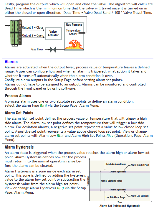
Electric valve control: supports fully open/fully closed valve drive, requires configuration of "Valve Travel Time" and "Dead Band" to avoid frequent adjustments. The algorithm automatically calculates the "Dead Time" (minimum action time=dead zone/100 x travel time) and is compatible with two-wire electric valves.
Sequencer control: Allocate a single power signal into 4 outputs, with "Output 1" being the "vernier output" (proportional signal, with the highest proportion) and "Output 2-4" being ON/OFF outputs. It supports two modes: "Linear" (fixed order) and "Progressive" (cyclic order), balancing the load wear of multiple heaters and pumps.
3. Alarm and safety functions (fault protection capability)
(1) Alarm function
Alarm instances: 8 independent alarm instances, supporting two types: "Process Alarm" (based on fixed threshold) and "Deviation Alarm" (based on set value deviation).
Configuration parameters: "High/Low Set Point" (high/low alarm threshold), "Hysteresis" (alarm hysteresis to avoid frequent triggering), "Latching" (locking, requiring manual reset), "Blocking" (blocking, temporarily not alarming when starting or setting value changes), "Silencing" (mute, temporarily closing output when alarming) can be set.
Alarm response: After the alarm is triggered, it can be linked to output (such as cutting off the load, starting the backup equipment), or uploaded to PLC/HMI through communication, supporting RUI interface pop-up prompts and sound and light alarms.
(2) Security features
Adaptation to hazardous areas: Modules with the end number "12" support Class 1 Div. 2 hazardous areas (Groups A-D, temperature code T4), and require the use of explosion-proof certified junction boxes and shielded armored cables. It is prohibited to plug and unplug live wires to avoid arcing.
Electrical safety: Maintain electrical isolation between analog input, digital I/O, and process output, with a grounding resistance of ≤ 4 Ω to prevent grounding loops; It is recommended to connect a 1A slow melting fuse (such as Littelfuse 0215001. MXP) in series with the power input terminal to prevent overload damage.
Permission management: Supports two levels of passwords (User/Administrator), with the User password only used for regular operations and the Admin password able to modify security settings; Optional 'Rolling Password', automatically changes after power failure, requires calculation of the current password using a formula (User Password=(pas.u × Code) Mod 929+70); Admin password=(pas. a x Code) Mod 997+1000 to prevent unauthorized access.
4. Communication and networking functions (system linkage capability)
(1) Support protocols and topology
Applicable scenarios for key parameters of communication protocol physical interface
Watlow Standard Bus EIA-485 (Slot C terminal: CF=common terminal, CD=T -/R -, CE=T+/R+) supports 17 nodes, with a maximum transmission distance of 1200 meters (shielded twisted pair) and a default baud rate of 9600bps for internal communication between modules, used for data exchange between RME and RMC/RMA
Modbus RTU EIA-485/232 (Slot C terminal: CC=common terminal, CA=T -/R -, CB=T+/R+) supports 247 nodes, baud rate 9600/19200/38400bps, 8-bit data bits, optional checksum (none/odd/even), communicates with PLC and HMI, uploads I/O status and alarm information, receives control commands
Extended protocol (RMA module required) Ethernet/EIA-485 supports EtherNet/IP, DeviceNet, PROFIBUS DP large-scale system networking, enabling remote monitoring and centralized control
(2) Networking standards and limitations
Topology requirement: EIA-485 adopts a "daisy chain" topology, and star/tree connections are prohibited. The first and last modules need to be connected to 120 Ω terminal resistors (to reduce signal reflection).
Wiring requirements: Communication lines and power lines should be wired separately (with a spacing of ≥ 10cm), using shielded twisted pair cables (such as CAT5 and above), and the shielding layer should be grounded at one end (grounded on the control room side and suspended on the site side).
Distance limit: EIA-485 has a maximum transmission distance of 1200 meters, while EIA-232 has a maximum transmission distance of 15 meters; When installing Split Rail, the maximum distance of Inter module Bus is 200 feet, and independent power supply is required to avoid voltage drop.
Installation and Wiring Guide
1. Installation process and precautions
(1) DIN rail installation (mainstream method)
Guide rail preparation: Confirm that the guide rail meets the EN50022 standard (35 × 7.5mm), clean the surface of the guide rail without oil stains or rust, and ensure that the guide rail is grounded (grounding resistance ≤ 4 Ω) if installed in a hazardous area.
Module fixation:
Insert the top hook of the module into the upper edge of the guide rail, rotate the module to a vertical position, and hear a "click" sound to indicate that the buckle is locked.
When installing multiple modules, horizontally splice the modules to ensure that the backplane connectors are fully in contact (without gaps). After installing the last module, check the overall flatness to avoid tilting.
Space reservation: A space of ≥ 76.2mm should be reserved at the top, bottom, and front of the module for heat dissipation and wiring operations; Avoid direct proximity to heating devices such as heaters and frequency converters (with a spacing of ≥ 150mm).
(2) Panel installation (optional)
Use the matching panel installation bracket (specified separately when ordering), drill holes according to the installation hole positions provided in the manual (spacing 58.67mm × 51.56mm), fix with # 8 × 3/4 inch screws, torque 10-15 in lb, and do not use washers (to avoid loose installation).
2. Wiring specifications and terminal definitions
(1) Core terminal function (Slot C is the common terminal, Slot A/B/D/E is the I/O terminal)
Terminal group terminal number functional wiring requirements
Slot C 98 power input+connect 20.4-30.8V AC/DC, distinguish polarity, and prohibit reverse connection; Suggest connecting 1A slow melting fuses in series
Slot C 99 power input - connected to the negative pole of the power supply. If it is powered by AC, the polarity of the neutral/live wire needs to be confirmed
Slot C CF/CD/CE Standard Bus CF=common terminal, CD=T-/R-,CE=T+/R+; Using shielded twisted pair cables, daisy chain connection, with 120 Ω resistors connected at both ends
Slot C CC/CA/CB Modbus RTU CC=common terminal, CA=T-/R-,CB=T+/R+; Support EIA-485/232 switching, requires configuration through module buttons
During the installation of Slot C CZ/CX/CY Inter module Bus, connect two rails using shielded twisted pair cables and single ended grounding
Slot A/B/D/E digital I/O terminals (such as B1/D1/D2...) digital input/output input: B1 is connected to the common terminal, D1-D6 is connected to the signal; Output: B1 is connected to the common terminal, D1-D6 are connected to the load; Need to distinguish between dry contacts/voltage input types
Slot A/B/D/E CT input terminals (such as T1/S1...) The current transformer inputs T1/S1 form a group and are connected to the secondary side of the CT; Ensure CT polarity is correct to avoid measurement errors
Slot A/B/D/E relay/SSR terminal (such as L1/K1...) relay/SSR output L1 is a normally open contact, K1 is a common terminal; AC loads need to distinguish between live and neutral wires, while DC loads need to distinguish between positive and negative poles
Slot A/B/D/E process output terminals (such as F1/H1...) process/retransmission output F1=voltage/current -, H1=voltage/current+; Select voltage or current output according to the configuration, and match the load impedance
(2) Safety wiring requirements
Electrical isolation: Digital I/O and process outputs need to be wired separately from power lines and high-voltage lines to avoid cross interference; Analog signal wiring requires the use of shielded wires, with the shielding layer grounded at one end.
Dangerous area wiring: UL 1015 certified wires are required for Class 1 Div. 2 areas, with terminal tightening torque ≥ 0.56 Nm, and the use of insulated damaged wires is prohibited; The junction box must be an explosion-proof certified model to avoid sparking.
Inductive load protection: When driving inductive loads such as relay coils and solenoid valves, RC suppressors (such as Watlow 08040147-0000) or freewheeling diodes should be connected in parallel at both ends of the load to prevent voltage spikes from damaging the module.
3. Typical System Networking Example
(1) Single rail I/O expansion system (Modbus RTU)
Composition: 1 RMA (Communication Gateway, Modbus RTU Master)+1 RMC (Temperature Controller)+2 RMEs (I/O Expansion, connected to 8 digital inputs and 4 SSR outputs respectively)+PLC (Modbus RTU Slave).
Wiring:
RMA's Slot C (CC/CA/CB) is connected to PLC's EIA-485 port, with a baud rate of 9600bps, no parity check, and 8 data bits.
RMA, RMC, and RME are connected via backplane Standard Bus (CF/CD/CE terminals) and share a 24V DC Class 2 power supply (Slot C 98/99).
The digital input terminals of RME1 are connected to temperature sensors and limit switches, while the SSR terminals of RME2 drive heaters and fans.
Function: RMC controls temperature, RME expands I/O to collect on-site signals and drive actuators, PLC reads system status through Modbus RTU and issues control instructions.
(2) Distributed Control System for Rail Division (EtherNet/IP)
Composition: Rail 1 (RMA+RMC x 2, control room), Rail 2 (RME x 3, on-site), connected via Inter module Bus, monitored by PC via EtherNet/IP.
Wiring:
The slot E (Ethernet terminals E1-E8) of RMA is connected to an Ethernet switch, and the PC is connected to the switch. The RMA fixed IP is set to 192.168.1.10, and the PC IP is set to 192.168.1.20.
The slot C (CZ/CX/CY) of rail 1 and rail 2 are connected using shielded twisted pair cables, with a maximum distance of 200 feet, and the shielding layer is grounded at one end.
Each guide rail is independently powered: Guide rail 1 uses a 60W power supply (0847-03000-0000), and guide rail 2 uses a 91W power supply (0847-0301-0000) to avoid voltage drop.
Function: On site RME connects sensors and actuators nearby to reduce wiring length; The control room monitors the status of all modules through EZ-ZONE Configurator software, enabling remote configuration and fault diagnosis.
Operation and Configuration Guide
1. Menu navigation (based on RUI remote user interface)
The RME module is operated through RUI (optional accessory) or software, and the menu is divided into three levels. The navigation logic is as follows:
Menu level entry method, core functions, common operation examples
Press and hold the Up+Down button for 3 seconds on the Operations page to display "oPEr" monitoring real-time data (I/O status, alarm status, timing/counting results), log status viewing, numerical input "di. S" (input status), alarm "a.st" (alarm status), and load current "Ld. Cu"
Long press the Up+Down key for 6 seconds on the Setup page to display "SEt" for configuring I/O parameters, logical relationships, alarm thresholds, communication parameter configurations, digital I/O direction "dir" (input/output), logical operations "fn" (and/or), and alarm threshold "a.hi/a.Lo"
Factory: Long press and hold the Advance+Infinity keys for 6 seconds to configure security permissions (password, rolling password), diagnostics (software version, IP address), calibration settings for User/Admin password "pas.u/pas.a", enable rolling password "roLL", and output "o.CA" during the calibration process
(1) Key configuration example: Digital input linkage alarm
Enter Setup → Digital I/O Menu → Digital I/O 1, set "dir=Input Dry Contact", "fn=Alarm" (associated alarm function), and "fi=1" (alarm instance 1).
Enter Setup → Alarm Menu → Alarm 1, set "a.ty=Process Alarm", "sr.a=Digital I/O" (alarm source is digital input), "is.a=1" (input instance 1), "a.hi=100" (high alarm threshold), "a.Lg=Close On Alarm" (output is closed when an alarm occurs).
Enter Operations → Alarm Menu → Alarm 1, view "a.st" (alarm status), when the digital input is triggered, the alarm status changes to "Alarm High", and the linkage output action is activated.
2. Software Configuration (EZ-ZONE Configurator)
(1) Software installation and connection
Download and installation: from Watlow official website( http://www.watlow.com )Download EZ-ZONE Configurator (free), supports Windows 7 and above systems, and the "Modbus Driver" component needs to be checked during installation.
Hardware connection: Use a USB-EIA-485 converter (such as B&B Electronics 485USBTB-2W) to connect the PC to the slot C (CF/CD/CE terminal) of the RME. The converter needs to install a driver and set up a COM port (such as COM5).
System scanning: Open the software, click on "Scan Network", select the COM port with a baud rate of 9600bps, and the software will automatically scan the RM module in the network, displaying the module model, address, and serial number.
(2) Core configuration: Modbus TCP settings (RMA module required)
Select the RMA module, enter the "Communications" tab, set "IP Address Mode=Fixed", IP=192.168.1.10, Subnet Mask=255.255.255.0, Gateway=192.168.1.1.
Enable "Modbus TCP Enable", set "Modbus Port=502" (default port), and "EtherNet/IP Enable" (if EtherNet/IP communication is required).
Enter the "Gateway" tab, enable "Gateway Instance 1-4", corresponding to RME module addresses 1-4, and set "Modbus Offset=0" (address offset free).
Click "Save" to save the configuration, restart the RMA module, verify network connectivity through "Ping 192.168.1.10" on the PC, and use Modbus testing tools (such as Modbus Poll) to read the I/O register of RME (such as address 40001=digital input 1 status).
3. Communication testing tools
Modbus RTU Test: Use Watlow Modbus RTU Diagnostic Tool, set baud rate=9600, address=1, read register 2500 (process value), and if the correct data is returned, communication is normal.
EtherNet/IP testing: Use Rockwell RSLogix software, add EtherNet/IP driver for RMA module, import GSD file (Part Number: 0601-0002-0000), read implicit assembly (Input Assembly=1, Output Assembly=2), and verify data interaction.
Maintenance and troubleshooting
1. Daily maintenance (preventive maintenance)
(1) Regular inspection (monthly)
Appearance and status inspection: Check the module indicator lights (Power light green constant light=normal, red constant light=power failure; The green flashing Comm light indicates active communication, and the constant red light indicates communication failure, with no error messages.
Wiring inspection: The terminals are not loose or oxidized, the shielding layer is well grounded, there is no parallel wiring between the communication line and the power line (spacing ≥ 10cm), and the wires have no insulation damage.
SD card check (if any): Check if the SD card is in place, with a remaining space of ≥ 10%, and regularly export data logs (to avoid full storage causing the logs to stop recording). It is recommended to back up once a month.
(2) Annual maintenance
Power test: Use a multimeter to measure the voltage at Slot C 98/99 terminals, ensuring that the ripple is ≤ 5% within the range of 20.4-30.8V; Check if the fuse (if any) is blown and there are no signs of heating in the power wiring.
Communication test: Use diagnostic tools to verify that all protocol communication is normal, Modbus RTU response time ≤ 100ms, Ethernet packet loss rate=0, EtherNet/IP cycle time ≤ 50ms.
Load test: Measure the current/voltage of the output terminal and compare it with the configured value, with a deviation of ≤± 1% (for example, the deviation between the SSR output current and the set value should be within ± 0.1A); Check that the relay/SSR contacts are not corroded and replace them if necessary.
2. Troubleshooting (problem location and resolution)
(1) Common faults and solutions
Possible causes of malfunction, troubleshooting steps, and solutions
The module has no display and the Power light is not on. 1. The power supply is not connected or the voltage is abnormal
2. The fuse is blown
3. Internal module fault 1. Measure the voltage at Slot C 98/99 terminals and confirm 20.4-30.8V
2. Check if the power input fuse (if any) is blown
3. Replace the spare module for testing. 1. Reconnect the wiring to ensure correct polarity
2. Replace the 1A slow melting fuse (Littelfuse 0215001. MXP)
3. Apply for RMA repair (provide module serial number and fault description)
Modbus communication failed, Comm light is red. 1. Address/baud rate mismatch
2. Wiring error (reversed polarity)
3. The terminal resistor is not connected or damaged
4. Excessive bus load 1. Verify the Modbus address, baud rate, and checksum between RME and PLC
2. Check the terminal wiring of Slot C CA/CB/CC to ensure that CA=T -/R -, CB=T+/R+
3. Measure the bus voltage (normal 2.5-5V), connect the first and last modules to a 120 Ω resistor
4. Check the number of bus nodes (≤ 32), if exceeded, add a repeater. 1. Unify communication parameters and restart the module to take effect
2. Correct the polarity of the wiring
3. Replace the terminal resistor
4. Add EIA-485 repeaters (such as B&B Electronics 485RPT)
Digital output unresponsive, load not operating. 1. I/O direction configuration error (set as input)
2. Output function not associated (fn=Off)
3. Load overload or short circuit
4. Relay/SSR damage 1. Enter Setup → Digital I/O Menu, confirm "dir=Output"
2. Check if 'fn' is associated with the correct function (such as Alarm, Logic)
3. Measure the load resistance and confirm that there is no short circuit and the current is ≤ the rated output value
4. Measure the output terminal voltage. If there is no voltage, replace the relay/SSR. 1. Reconfigure the I/O direction and restart to take effect
2. Associate correct functional instances
3. Repair the load short circuit and replace the overloaded equipment
4. Replace the relay module or SSR component (original spare parts are required)
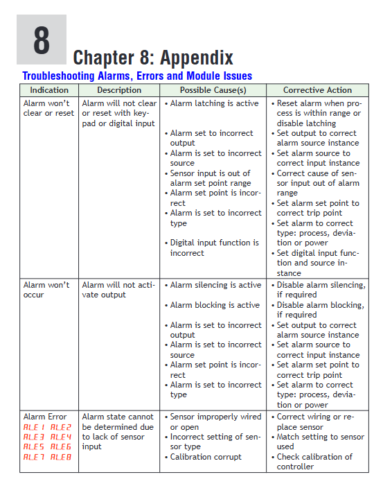
Alarm not triggered, a.st displays "None". 1. Alarm threshold setting error (above/below normal range)
2. Alarm source selection error (sr.a=None)
3. Alarm blocking enabled (a.bL=Startup/Set Point)
4. The alarm lag is too large (a.hy>deviation value). 1. Enter Operations → Alarm Menu and compare the process value with the alarm threshold
2. Enter Setup → Alarm Menu, confirm that "sr.a" selects the correct source (such as Digital I/O, Current)
3. Check if "a.bL" is "Off" and if the blockage is lifted after startup
4. Reduce the "a.hy" value (such as changing from 5 ℃ to 1 ℃). 1. Adjust the alarm threshold to ensure coverage of the abnormal range
2. Select the correct alarm source and associate it with an instance
3. Turn off the alarm blocking or wait for the blocking time to end
4. Adjust the lag to a reasonable value
(2) Meaning of indicator lights and fault logs
Indicator light status meaning investigation direction
Power (green) is constantly on, and the power supply is normal-
Power (red) constantly on. Abnormal power supply (overvoltage/undervoltage, short circuit). Measure the power supply voltage and check the power supply wiring
Comm (green) flashing (once/second) communication active, data exchange normal-
Comm (red) constantly on communication fault (address error, wiring error, protocol mismatch). Check communication parameters and wiring
SD Card (green) flashing SD card read/write in progress-
SD Card (red) always on. SD card fault (unrecognized, damaged, full storage). Re insert and unplug the SD card, format or replace it, and clear the log
Fault log viewing: Go to Factory → Diagnostics Menu and check the "Error Code" (such as "E01=Communication Fault" and "E02=Output Short Circuit") “Software ID”“Serial Number”, After recording the information, contact Watlow technical support for troubleshooting.
Typical application scenarios
1. I/O expansion of semiconductor wafer heat treatment equipment
System composition: 1 RMA (EtherNet/IP gateway)+2 RMCs (temperature control, controlling wafer heating chamber)+3 RMEs (I/O expansion) deployed in semiconductor cleanrooms.
Function implementation:
RME1: Connect 16 digital inputs (chamber door switch, wafer in place sensor) and 8 SSR outputs (driving chamber heating lamp).
RME2: Connect 8 CT inputs (monitor heating lamp current) and 4 process outputs (control nitrogen flow valve).
RME3: Implement interlocking protection for "door not closed → heating stop" and "abnormal current → alarm" through logical operations, and control the duration of wafer heating through timing function.
Value: Distributed I/O reduces cleanroom wiring, logical interlocking enhances equipment safety, and EtherNet/IP enables data exchange with MES systems.
2. Temperature and valve control of chemical reaction kettle
System composition: 1 RMA (Class 1 Div. 2 certification)+1 RMC (temperature control)+1 RME (special equipment control), deployed in the chemical explosion-proof workshop.
Function implementation:
RMC controls the temperature of the reaction vessel, while RME drives the feed valve through the "Motorized Valve" function, configured with "Valve Travel Time=120 seconds" and "Dead Band=2%" to avoid frequent valve adjustments.
RME is connected to 4 CT inputs to monitor the current of the mixing motor. When the current is abnormal, an alarm is triggered and the feeding valve is cut off.
Explosion proof junction boxes and armored shielded wires are used, which comply with Class 1 Div. 2 safety requirements and prohibit live plugging and unplugging of wires.
Value: Explosion proof design suitable for hazardous areas, precise valve control to enhance reaction stability, current monitoring to prevent equipment failure.
3. Timing control of food processing production line
System composition: 1 RMA (Modbus RTU)+1 RMC (oven temperature control)+2 RME (timing and logic control), used for biscuit baking production line.
Function implementation:
RME1: Use the "Sequencer" function to distribute the oven heating power into 4 outputs (1 vernier+3 ON/OFF), use the "Progressive" mode to balance heater wear, and set "Minimum On Time=60 seconds".
RME2: Control the speed of the conveyor belt through timing function (linked to the temperature of the oven), and implement the interlock of "oven not reaching temperature → conveyor belt stop" through logical operation.
PLC reads the production line status through Modbus RTU and issues start stop commands.
Value: Sequencer function extends heater life, timing interlock improves production efficiency, Modbus communication enables centralized monitoring.
- OMRON
- ABB
- General Electric
- EMERSON
- Honeywell
- HIMA
- ALSTOM
- Rolls-Royce
- MOTOROLA
- Rockwell
- Siemens
- Woodward
- YOKOGAWA
- FOXBORO
- KOLLMORGEN
- MOOG
- KB
- YAMAHA
- BENDER
- TEKTRONIX
- Westinghouse
- AMAT
- AB
- XYCOM
- Yaskawa
- B&R
- Schneider
- KONGSBERG
- NI
- WATLOW
- ProSoft
- SEW
- ADVANCED
- Reliance
- TRICONEX
- METSO
- MAN
- Advantest
- STUDER
- DANAHER MOTION
- Bently
- Galil
- EATON
- MOLEX
- DEIF
- B&W
- ZYGO
- Aerotech
- DANFOSS
- Beijer
- Moxa
- Rexroth
- Johnson
- WAGO
- TOSHIBA
- BMCM
- SMC
- HITACHI
- HIRSCHMANN
- Application field
- XP POWER
- CTI
- TRICON
- STOBER
- Thinklogical
- Horner Automation
- Meggitt
- Fanuc
- Baldor
- SHINKAWA
- Other Brands
- UniOP
- KUKA
- Iba
- Beckhoff
-
 Basler DECS-100-B15 Digital AVR
 -
 Basler 9284900103 PS DECS-400N
 -
 Basler D4N3H1U Intertie Protection
 -
 Basler DECS-100-B15 A15 AVR
 -
 Basler KR4F Voltage Regulator
 -
 Basler BE26434 T14 Transformer
 -
 Basler SR8A-2B15B3A Regulator
 -
 Westinghouse 774B472A12 AR Relay
 -
Basler DECS-100-B15 AVR
-
 Basler XR2002F Regulator 110V
 -
 Basler SR125-E Static Regulator
 -
 Basler SSR 125-12 Regulator
 -
 Basler MOC2599 Motor Pot
 -
 Basler BE1-DFPR Feeder Relay
 -
 Basler CBS 305 Current Boost
 -
 Basler BE1-25 AutoSync
 -
 Basler MVC 300 Voltage Control
 -
 Basler BE3-25A AutoSync
 -
 Basler KR7FF Static Regulator
 -
 Basler 90-49000-100 Regulator
 -
 Basler 880 kVA Dry Type Transformer Specs
 -
 Basler Electric BE1-25 Sync-Check Relay Specs
 -
 Basler SSR 125-12 Voltage Regulator Specs
 -
 Basler Electric BE1-851 Overcurrent Relay Review
 -
Basler Electric 149D930G02 Control Sub-Assembly
-
 Basler Electric BE1-81O/UT Frequency Relay Specs
 -
 Basler Electric BE1-51/27C Overcurrent Relay
 -
 Basler Electric 149D956G02 Industrial Component
 -
Basler Electric BE1-51A Overcurrent Relay Specs
-
 Basler Electric BE1-40Q Loss of Excitation Relay
 -
 Basler DECS-200 Excitation Control System
 -
 Basler DECS-200 Voltage Regulator 56-277V AC / 125V DC
 -
 Basler BE1-87T Transformer Differential Relay
 -
 Basler RDP-110-S1 Protection Relay
 -
 Basler BE1-700V Digital Protective Relay
 -
 Basler BE1-951 Overcurrent Protection System
 -
 Basler DECS-300 Digital Excitation Control
 -
 Basler DECS-200 Digital Excitation Control
 -
 Basler DECS-200-1C Excitation Control System
 -
Basler DECS-200-1L Digital Excitation Control
-
 Basler Electric BE1-GPS Generator Protection System
 -
Basler Electric DECS-200-1C Digital Excitation Controller
-
 Basler Electric DECS125-15 Excitation Control with Power Module
 -
 Basler Electric BE1-87G Differential Relay
 -
 Basler Electric BE1-11 Protection System I5A3M2P2N0EA00
 -
Basler Electric DECS-200-1C Excitation Control System
-
Basler Electric BE1-11g Generator Protection Relay
-
 Basler Electric DECS 125-15-B2C1 V2.0.9 Excitation Control
 -
 Basler Electric BE1-81O/UT3ED1JA7N2F Frequency Relay
 -
Basler Electric BE1-81O/UT3EE1YB7N1F Frequency Relay
-
 Basler Electric DECS-200-1L Digital Excitation Control System
 -
Basler DECS125-15-B2C1 Excitation Control
-
 Basler 9507900205 SSR Retrofit Voltage Regulator
 -
 Basler BE2000E Digital Voltage Regulator
 -
 Basler BE1-GPS Generator Protection System
 -
Basler DECS-250-CN1CN1N Digital Excitation Control
-
 Basler DGC-2020 Genset Controller
 -
 Basler BE1-81O UT3ED1LA7N0F Frequency Relay (Variant)
 -
 Basler BE1-81O UT3EE1YA9S0F Frequency Relay (Variant)
 -
Basler BE1-81O Over/Under Frequency Relay
-
Basler DECS125-15 Digital Excitation Control
-
Basler Electric BE1-951 Overcurrent Protection System
-
 Basler Electric BE1-700V Digital Protective Relay
 -
 Basler Electric APR63-5 Automatic Voltage Regulator
 -
Basler Electric BE1-851 Overcurrent Protection System
-
Basler Electric DECS-250-LN1SN1N Excitation Control
-
 Basler Electric BE1-87T Transformer Differential Relay
 -
Basler Electric DECS-200-1L Excitation Control System
-
 Basler Electric 9310300100 DECS-300 Excitation Control
 -
 Basler Electric SSE-N 125-4.5KW Shunt Exciter Regulator
 -
 Basler Electric DGC-2020HD-5NS1DNSBA Genset Controller
 -
Basler Electric BE1-81-O/UT3EE1JB7N1F Frequency Relay
-
Basler Electric BE1-81T1EE1WA0N1F Frequency Relay
-
 Basler Electric BE1-25M1EA6PN5R1F Sync-Check Relay
 -
 Basler Electric BE1-GPS Generator Protection System
 -
Basler Electric DECS-250-LN1SN1N Excitation Control Rev V
-
 Basler Electric DECS-250-CN2CN1N Excitation Control
 -
Basler Electric BE1-50/51B-207 Overcurrent Relay
-
Basler Electric DECS-300-C0N0 Excitation Control System
-
Basler Electric DECS-200 Digital Excitation Control System
-
Basler Electric DECS-250-LN1CN1N Excitation Unit
-
Basler Electric DECS-250 LN2SA1D Excitation Unit Specs
-
Basler Electric BE1-87T Transformer Relay Review
-
Basler Electric BE1-11 Protection System
-
Basler Electric BE1-GPS100-E4N1H1N Protection System
-
 Allen-Bradley 442G-MABH-R Safety Module
 -
 Beckhoff CX1030-0111 PLC Assembly Profile
 -
 FANUC IC693CPU364 PLC Module
 -
 Orange Denmark Type 200816 220 PLC Specs
 -
 OMRON C200H-SNT31 Sysmac PLC Module
 -
 Allen Bradley 20AB022A3AYNANC0 PowerFlex 70
 -
 OMRON C200HW-PCU01 Position Control Unit
 -
 ABB AO845A-eA Analog Output Module
 -
 OMRON CJ1M-CPU22 CPU Unit
 -
 Allen Bradley 100-E265ED11 Contactor
 -
 Honeywell 51304511-100 Interface Module
 -
 SOLEXY BXF3S0101N0018 Gateway Module
 -
 OMRON CJ2H-CPU65 CPU Unit
 -
 Automation Direct GS2-45P0 AC Drive
 -
 M68-2000 2-Axis Motion CNC Controller
 -
 OMRON CJ1M-CPU11 V3.0 PLC CPU Unit
 -
 OMRON CJ1W-NC413 4-Axis Positioning Controller
 -
 OMRON 3G2A3-PRO16 Programming Console HMI
 -
 Siemens 3VT8440-2AA04-2GA2 Molded Case Circuit Breaker
 -
 Siemens 3RT5045 Contactor Series
 -
 OMRON C200HS-CPU01-E SYSMAC PLC Controller
 -
 OMRON C500-NC103-E Positioning Control Unit
 -
 OMRON CJ1W-TC001 Temperature Control Unit
 -
 OMRON NJ301-1100 NJ-PA3001 PLC System EtherCAT
 -
 Pilz 773100 M1P Safety Relay Base Unit
 -
 Siemens SINUMERIK 840D SL NCU 720.3B with PLC 317-3 PN/DP
 -
 Siemens 6AV6618-7GD01-3AB0 HMI Panel
 -
 OMRON F150-C15E-3 Vision Mate Controller PLC Overview
 -
 Mitsubishi MELSEC A Series PLC System A63P A3ACPU A616AD A68RD3
 -
 M68-2000 2 Axis Motion Controller SCE SERVO CNC
 -
 OMRON FZ-S2M PLC Camera Vision System
 -
 VISOLUX SLVA-4K PLC Module from Elektronik GmbH
 -
 OMRON CJ1M-CPU23 V2.0 PLC CPU Unit
 -
 ABB AI86-16CHF PCB Card 5761751-9 B Specifications
 -
 Allen-Bradley 100-D140ZJ22L Contactor Overview
 -
 Merlin Gerin PB80 PLC Rack
 -
 WEIR WE203 Power Supply PLC
 -
 OMRON NX-TS3102 Temperature Input Unit
 -
 Siemens 6ES7146-6FF00-0AB0 I/O Module
 -
 Fanuc A16B-3300-0057 Circuit Board
 -
 OMRON CJ1W-IDP01 Input Module
 -
 Siemens 6FX2007-1AD13 Handheld Unit
 -
 Gems EM54 PLC Module PCB


