
YASKAWA AC Drive G7 Series (Model CIMR-G7U)
YASKAWA AC Drive G7 Series (Model CIMR-G7U)
Basic Information and Security Core Guidelines
1. Positioning
The core technical document of the G7 series communication drive (model CIMR-G7U) covers the entire lifecycle of product safety specifications, model specifications, installation and wiring, operation modes, parameter settings, trial operation and maintenance, troubleshooting, etc. The target audience is trained authorized personnel (installers, maintenance engineers, etc.) who must strictly follow the manual guidance to ensure the safe and stable operation of the equipment.
2. Core security standards that cannot be violated
(1) Electrical safety
The iron rule for power-off operation: Before wiring, removing the cover plate (terminal cover, front cover), and touching the circuit board, all power sources must be disconnected, and the internal capacitor must be discharged (at least 5 minutes until the CHARGE indicator light goes out). After the discharge is completed, the DC bus voltage (below 50Vdc) must be measured to confirm safety and avoid electric shock.
Prohibited live operation: It is strictly prohibited to connect/disconnect wires, plug and unplug digital operators with live power, and it is forbidden to remove the protective cover when the power is turned on, otherwise it may cause electric shock or equipment short circuit.
Power matching requirements: Before powering on, it is necessary to confirm that the rated voltage of the driver is consistent with the input power supply (200-240V level/380-480V level), otherwise it may cause a fire or equipment burnout.
(2) Equipment protection and operation restrictions
Prohibition of modification and withstand voltage testing: It is not allowed to modify the driver body or circuit without authorization (modification will directly result in warranty failure), and no component shall be subjected to withstand voltage testing - the equipment contains sensitive semiconductor devices, and high voltage can cause irreversible damage.
Output terminal limitation: The output terminals (U/T1, V/T2, W/T3) must not be connected to AC power, phase-shifting capacitors, LC/RC noise filters, or electromagnetic contactors (closing the contactor during operation will generate surge current, triggering overcurrent protection) 、 .
Static electricity protection: When in contact with the control board or CMOS IC, it is necessary to follow the ESD (electrostatic discharge) process (such as wearing an anti-static wristband) to avoid static electricity damaging the circuit.
Product Model and Receipt Confirmation
1. Model system and specification classification
The G7 series drivers are divided by voltage level and protection type, covering different power requirements. The core parameters are as follows:
Classification dimension specific specification remarks
Voltage level 200-240V (3-phase): maximum motor capacity 0.4kW-110kW; 380-480V (3-phase): 0.4kW-300kW. In the model, "2" represents the 200-240V level, and "4" represents the 380-480V level (such as CIMR-G7U20P4 which has a 200V level of 0.4kW)
Protection type open enclosure (IEC IP00): to be installed inside the control cabinet; Enclosed wall mounted (IEC IP20/NEMA 1): can be directly wall mounted. Enclosed type requires the installation of a top protective cover to meet IP20 requirements
Output capacity of 200V level: 1.2kVA (0.4kW) -160kVA (110kW); 480V level: 1.4kVA (0.4kW) -460kVA (300kW) requires matching motor rated capacity (recommended 50% -100% driver capacity)
2. Receipt inspection and preparation
(1) Must check items
Model and appearance: Verify that the packaging label model matches the order, check that the drive housing is free of collisions or scratches, that the terminals are not deformed, and that the digital operator is not damaged.
Component integrity: Confirm that the packaging contains the driver body, digital operator, terminal cover, fixing screws (M3/M3.5, etc.), and installation manual (1 copy in both Chinese and English). If missing or damaged, immediately contact the supplier.
(2) Preparation before installation
Tool list: Cross screwdriver (M4/# 1/# 2), straight screwdriver (blade thickness 0.4mm/blade width 2.5mm), wire stripping pliers, 6mm wrench (tightening torque of 0.5-0.7N · m for bolts), wire crimping pliers (for crimping terminals).
Environmental confirmation: The installation surface should be made of non combustible materials such as metal, kept away from oil mist, dust, radioactive substances, and corrosive gases. The environmental temperature/humidity should meet the requirements (open type: -10~+45 ℃, ≤ 95% RH; closed type: -10~+40 ℃, ≤ 95% RH).
Full process specification for installation and wiring
1. Key installation requirements
(1) Installation location and space
Installation direction: It must be installed vertically to avoid horizontal or inclined installation (which will reduce heat dissipation efficiency and cause overheating).
Cooling space: A minimum space of 50mm in the horizontal direction and 120mm in the vertical direction should be reserved for single installation. When multiple units are installed side by side, if the spacing is insufficient, a cooling fan or air conditioner should be installed in the control cabinet to ensure that the inlet air temperature is ≤ 45 ℃.
Special note: For models of 18.5kW and above, space for eyebolts and main circuit cables must be reserved. For enclosed installations of 15kW and below, top/bottom protective covers must be removed to meet heat dissipation requirements.
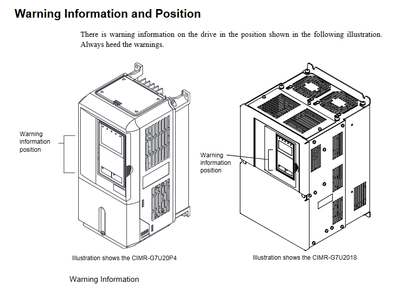
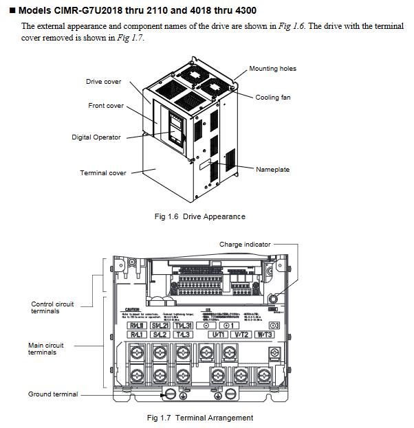
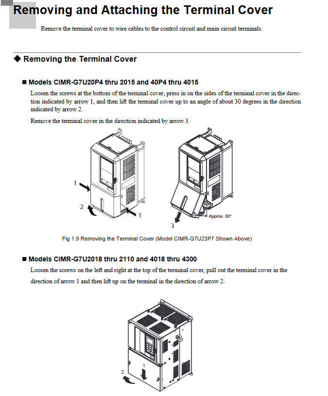
(2) Dismantling and resetting of cover plate
Terminal cover disassembly: Low power models (20P4-2015/40P4-4015): Loosen the bottom screws, press both sides and lift them up 30 ° before removing them; High power model (2018-2110/4018-4300): Loosen the top left and right screws, pull out and lift up.
Disassembly of digital manipulator: Press the side buckle of the manipulator and lift it up to remove it. When installing, the front cover should be installed first before installing the manipulator to avoid poor contact and malfunction.
2. Wiring specifications (main circuit+control circuit)
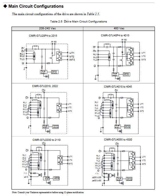
(1) Main circuit wiring
Cable specifications: Select the appropriate cable according to the model (for example, 2mm ² (14AWG) cable is recommended for the main circuit of the 200V level 0.4kW model, and 325mm ² cable is required for the 480V level 300kW model), using UL certified copper wire (75 ℃ temperature resistance).
Terminal torque: The torque of different terminal screws varies, such as M4 screws with a torque of 1.2-1.5N · m and M8 screws with a torque of 9.0-10.0N · m. Loosening can easily cause heating and fire, while tightening can easily damage the terminals.
Grounding requirements: The grounding resistance for 200V level should be ≤ 100 Ω, and for 480V level it should be ≤ 10 Ω. The grounding cable should be independent (not shared with welding machines or power tools) and the length should be as short as possible. Multiple drivers should be grounded to avoid forming loops.
(2) Control circuit wiring
Cable requirements: Use shielded twisted pair cables (recommended 0.75mm ²/18AWG), separate them from the main circuit cables (spacing ≥ 30cm), and connect the shielding layer to the driver grounding terminal (E (G)).
Terminal function: The digital input terminals (S1-S12) are 24Vdc/8mA optocoupler isolated and used for forward and reverse rotation, fault reset, etc; Analog input terminals (A1-A3) support 0- ± 10V/4-20mA signals; The capacity of relay output terminals (MA/MB/MC, etc.) is 250VAC/30VDC/1A.
Wiring inspection: After completion, it is necessary to confirm that there are no broken wires touching other terminals, no foreign objects remaining, and screws tightened. It is prohibited to use a buzzer to detect the control circuit.
Operation mode and digital manipulator
1. Core operating mode
The drive includes 5 core modes, covering requirements such as parameter settings, operation monitoring, and self-tuning:
Mode Name Core Function Operation Scenario
Drive mode monitors operational data (frequency, current, voltage), checks fault information, performs start stop operations, daily operation monitoring, and troubleshooting
Quick programming mode (Quick) sets basic parameters (control mode, frequency reference source, acceleration and deceleration time, motor rated parameters) for the first trial run, quickly configuring core parameters
Advanced Programming Mode (Adv) for viewing/modifying all parameters (PID, torque compensation, carrier frequency, etc.) in complex application scenarios (such as PID control, multi-stage operation) that require fine tuning of parameters
Verify mode only displays parameters that are different from the factory default values to confirm the modification results and avoid missing them
Before vector control, ensure that the driver matches the motor characteristics (by disconnecting the motor load) in the self-tuning mode (A. Tune) for automatic calibration of motor parameters (rotation self-tuning/static self-tuning)
2. Use of digital manipulators
(1) Key function
The core buttons include: LOCAL/REMOTE (switch local/remote control), MENU (mode selection), ESC (return to previous level), JOG (jog operation), FWD/REV (forward/reverse selection), RUN/STOP (start/stop), DATA/ENTER (confirm input).
Fault reset: When the drive reports a fault, press the Shift/RESET key to reset (the cause of the fault needs to be confirmed first).
(2) Meaning of indicator lights
FWD/REV: lit up indicates that the current command is forward/reverse; ALARM: Constant illumination indicates a fault, while flashing indicates an alarm; RUN: Constant light indicates running, flashing indicates decelerating; STOP: Constant light indicates a stop, while flashing indicates a frequency lower than the minimum output frequency.
Core content of parameter settings
1. Required basic parameters
First use requires priority configuration of the following parameters to ensure the normal operation of the device:
Parameter number, parameter name, function description, factory default value (200V level 0.4kW)
A1-02 Control mode selection: 0=V/f control, 2=open-loop vector control 1 (default), 3=flux vector control 2
B1-01 frequency reference source selection 0=digital operator, 1=control terminal (analog input) 1
B1-02 Run Command Source Selection 0=Digital Operator, 1=Control Terminal (Contact Signal) 1
C1-01 Acceleration Time 1 Acceleration time from 0 to maximum frequency (seconds) 10.0s
C1-02 Deceleration time 1 Deceleration time from maximum frequency to 0 (seconds) 10.0s
E1-01 Input Voltage Setting Driver Rated Input Voltage (200V for 200V level, 400V for 480V level) 200V
E2-01 motor rated current The rated current on the motor nameplate (ampere) is 1.90A
L1-01 motor overload protection selection 1=standard fan cooling motor protection (default), 3=vector motor protection 1
2. Key Explanation of Functional Parameters
Self tuning parameters (T1 series): Set T1-01 to 0=rotational self-tuning (motor no-load operation calibration), 1=static self-tuning (motor does not rotate, only partial parameters are measured), and input the motor nameplate parameters (power, voltage, frequency, number of poles).
PID control parameters (b5 series): b5-01 set 1=PID enable, b5-02=proportional gain (default 1.00), b5-03=integration time (default 1.0s), used for closed-loop control of pressure, flow, etc.
Torque compensation parameter (C4 series): C4-01=torque compensation gain (default 1.00), increases when low load vibration occurs, and increases when low-speed torque is insufficient.
Trial operation and maintenance
1. Trial operation process
(1) No load trial operation
After confirming that the wiring is correct, turn on the power and check that the digital operator displays normally (without any fault codes);
Switch to LOCAL mode, set the low frequency (such as 5Hz), press the RUN button, and confirm that the motor rotates correctly (if reversed, swap any two output terminals U/T1, V/T2);
Gradually increase the frequency to the rated value, monitor the output current (there should be no abnormal fluctuations), and press the STOP button to confirm that the deceleration is normal.
(2) Load trial operation
Connect the motor and load after power failure to ensure that the mechanical system is unobstructed;
Starting from low frequency (10% rated frequency), check the stability of the load operation and ensure there are no abnormal noises or vibrations;
Gradually increase to the operating frequency and confirm that the output current is ≤ the rated current of the motor. If overcurrent/overload occurs, adjust the acceleration/deceleration time or check the load.
2. Maintenance and upkeep
(1) Daily inspection
Check the drive for any abnormal noise or odor, and ensure that the cooling fan is running normally;
Confirm that the digital operator displays normally without any fault/alarm codes;
Check that the terminal screws are not loose and the cables are not aged or damaged.
(2) Regular maintenance (every 6 months to 1 year)
Clean the dust inside the drive (using compressed air, pressure ≤ 0.3MPa);
Check the wear of the cooling fan bearings (replace if there is any abnormal noise);
Measure the capacitance of the main circuit (if it is lower than 80% of the initial value, it needs to be replaced).
Common fault handling
Fault code, fault cause, and solution measures
OC output short circuit, motor overload, short acceleration time. Check whether the output cable is short circuited, reduce the load, and extend the acceleration time (C1-01)
The UV input voltage is too low, the capacitor discharge is incomplete, and the power supply fluctuation confirms that the input voltage meets the requirements. Wait for the capacitor to fully discharge (≥ 5 minutes) and install a voltage regulator device
OL1 motor overload (exceeding thermal protection time), reduce load, check motor heat dissipation, adjust L1-02 (overload protection time)
PGO PG (encoder) disconnection, wiring error check PG cable connection, confirm PG model matches parameter F1-01 (PG pulse number)
- OMRON
- ABB
- General Electric
- EMERSON
- Honeywell
- HIMA
- ALSTOM
- Rolls-Royce
- MOTOROLA
- Rockwell
- Siemens
- Woodward
- YOKOGAWA
- FOXBORO
- KOLLMORGEN
- MOOG
- KB
- YAMAHA
- BENDER
- TEKTRONIX
- Westinghouse
- AMAT
- AB
- XYCOM
- Yaskawa
- B&R
- Schneider
- KONGSBERG
- NI
- WATLOW
- ProSoft
- SEW
- ADVANCED
- Reliance
- TRICONEX
- METSO
- MAN
- Advantest
- STUDER
- DANAHER MOTION
- Bently
- Galil
- EATON
- MOLEX
- DEIF
- B&W
- ZYGO
- Aerotech
- DANFOSS
- Beijer
- Moxa
- Rexroth
- Johnson
- WAGO
- TOSHIBA
- BMCM
- SMC
- HITACHI
- HIRSCHMANN
- Application field
- XP POWER
- CTI
- TRICON
- STOBER
- Thinklogical
- Horner Automation
- Meggitt
- Fanuc
- Baldor
- SHINKAWA
- Other Brands
- UniOP
- KUKA
- Iba
- Beckhoff
-
 OMRON C60H C6DR DE V1 Sysmac PLC
 -
 MITSUBISHI ELECTRIC A2ACPU21 S1 CPU Module
 -
 ABB BAILEY INNPM12 Network Process Module
 -
 HONEYWELL 620 0073C IPC PLC Module
 -
 Mitsubishi 15050 PR02B PLC Circuit Board
 -
 SIEMENS 6SY7000 0AC37 Drive Control Module
 -
 OMRON TJ2 ECT16 Traxial EtherCAT Controller
 -
 GE Fanuc IC698PSD300D Power Supply Module
 -
 Texas Instruments Series 505 16 Position Base
 -
 OMRON YASKAWA SGDH 10DE OY Servo Drive
 -
 Allen‑Bradley 440G-MT Safety Interlock Switch Specs
 -
 Rubycon PD27A 24V 8A Power Supply Module
 -
 SK-H1-GDB1-F11D PLC Gate Driver Board Kit
 -
 VIPA 441-4UA14 451-4UA14 PLC Module Rack
 -
 Mitsubishi FX5U-80MT ESS PLC Controller Specs
 -
 Mitsubishi Q64TCRTN Temperature PLC Module
 -
 GE 1C31170G Rev10 PLC Circuit Board Module
 -
 Schneider TWDLMDA40DTK PLC Controller Module
 -
 Omron FQM1-MMA22 Motion Control Module Specs
 -
 OMRON CJ1W-NCF71 Position Control Unit Specs
 -
 Schneider TSXETY4103 Ethernet Module
 -
 Mitsubishi Q12PHCPU Process CPU
 -
 Yaskawa 3G3HV-A4022-CE AC Drive
 -
 Cincinnati Milacron 3-533-0669G Temperature Control Board
 -
 Allen Bradley 20AC030A3AYNANC0 PowerFlex 70 Drive
 -
 Siemens 6ES7314-6BG03-0AB0 CPU 314C-2 DP
 -
 Carrier 17EX54007903 PLC Module
 -
 OMRON CS1W-V600C12 ID Controller Module
 -
 Honeywell 51402755-100 PCB Card
 -
 Heidenhain ECN 113 Rotary Encoder
 -
 OMRON B7AM-8B16 I/O Terminal Block
 -
 Fanuc A06B-6110-H026 Power Supply Module
 -
 Schneider TSXETG3021 Ethernet Gateway
 -
 OMRON CS1W-CLK21-V1 Controller Link Unit
 -
 NP1W6406T-Z704 PLC I/O Module
 -
 OMRON CJ1W-DA08C Analog Output Module
 -
 Yaskawa 3G3HV-A4022-CE AC Drive
 -
 OMRON NB7W-TW01B CP1L-EL20DR-D Power Panel
 -
 OMRON C500-NC103-E Position Control Unit
 -
 Steag Hamatech PLC DCS Servo Control System
 -
 Siemens 6SN1123-1AA00-0DA1 Power Supply Module
 -
 GE IC693CHS391H CPU & AD693CMM301A PLC Module
 -
 Siemens 6FC5303-0AF23-1AA1 PLC Control Panel
 -
 Square D CM4000T PowerLogic Circuit Monitor J1 F16
 -
 Siemens 6FX5002-5DG10-1BA0 MOTION-CONNECT 500 Cable
 -
 Schmersal SRB324ST 101195504 Safety Relay 24V
 -
 Mitsubishi 15050-PR02A PLC Circuit Board Module
 -
 OMRON CQM1-AD041 Analog Input PLC Module
 -
 Beckhoff EL5042 EtherCAT PLC Terminal Module
 -
 OMRON C200HW-MC402-E Motion Control Unit
 -
 C36TC0UA1100 Industrial Temperature Controller
 -
 NL8048BC24 12 Industrial Control LCD Module
 -
 OMRON R88D Servo Drive and Motor System
 -
 OMRON CS1W CLK21 V1 Controller Link Module
 -
 OMRON YASKAWA R7M A20030 S1 D Servo Motor
 -
 SIEMENS 6AV2128 3KB06 0AX1 Unified Comfort Panel
 -
 Schneider Electric METSEPM8240 PowerLogic Meter
 -
 Advanced AMCI 1PLC 1 31F Programmable Limit Switch
 -
 ABB PM582 ETH Programmable Logic Processor
 -
 SIEMENS 6FC5110 0CB01 0AA0 CPU Control Board
 -
 Schleicher P03GS13A CPU Module
 -
 Siemens 6SN1123-1AA00-0BA1 Power Module
 -
 Mitsubishi A1S61PN Power Supply Module
 -
 Yaskawa CPS-IONB DC Power Supply Module
 -
 Siemens 6ES7215-2BD00 CPU 215-2
 -
 Mitsubishi A2ACPU MELSEC PLC System Kit
 -
 ProSoft 3150-MCM Communication Module
 -
 Mitsubishi OSE104ET Incremental Encoder
 -
 OMRON CJ1W-AD081-V1 Analog Input Module
 -
 Broadcom BCM5464A1KRB Quad Port Ethernet IC
 -
 Modicon M221-24IO TM221C24 PLC 24 PNP Transistor
 -
 Allen-Bradley 1321-3R160-B Line Reactor 3R160B
 -
 Beckhoff CX1020-0012 Embedded PLC Module Specs
 -
 Turck BL20-PF-24VDC-D Power Feed Module Specs
 -
 Siemens 6SY7000-0AC37 Power Supply Module
 -
 Yaskawa SGDH-10DE-OY 1kW 400V Servo Drive Specs
 -
 Omron 3G3SV-BB015-E 1.5kW 220V VFD Specs
 -
 Uni-Pro CPU91-PLC J 23.020167X Processor Module
 -
 PASABAN MTC-3044 PLC Rack Power Supply 4835-A
 -
 XYCOM 3015T Operator Interface Panel BIN4.4.4
 -
 OMRON CJ1W-MD261 Mixed I/O Module
 -
 Omron NJ301-1100 PLC CPU eCat EIP Specs
 -
 Omron F500-C15-ETN Vision System PLC Module
 -
 Modicon M241-24IO TM/T2UK PLC with Ethernet
 -
 SIXNET YS-800-001 RTU PLC Module
 -
 BEMAC UST-202-D Interface Board 1307D V08B2
 -
 Yaskawa JANCD-MMOIC-02 Drive Circuit Board
 -
 ABB 3BSE005028R1 SDCS-COM-1 Comm Board
 -
 Omron 3G3MX2-A4110 A4150 Inverter Drives Specs
 -
 KEYENCE CA-E100 PLC Module
 -
 GE IC693ALG223-GB Analog Input Module Specs
 -
 ABB BAILEY IMMFP01 Multi Function Processor System
 -
 SIEMENS 6FC5372 0AA00 0AA1 NCU 7202 Controller
 -
Modicon TM241CE4 40I O Transistor Programmable Controller
-
 SIEMENS 6ES7 315 2EH13 0AB0 CPU 3152 PN DP
 -
 NORIS A1 91 PCB Card Rack Module System
 -
 SIEMENS 6ES7 313 5BE01 0AB0 Compact CPU
 -
 SCHNEIDER ELECTRIC S144B MICROLOGIC 60A Trip Unit
 -
 CNI PLC269 v3 Control Module Board Rev H
 -
ABB BAILEY IIMCP02 Processor Module
-
 OMRON NT20S ST121 EV3 Operator Interface Terminal
 -
 OMRON NS-CA001 Video Input Unit
 -
 GE Fanuc IC695CHS012 RX3i Backplane
 -
 Allen Bradley 2711E-K14C6 PanelView 1400e Terminal
 -
 Siemens Sinamics CCB 10000432.71 Power Cell
 -
 Siemens 6SL3210-1SE21-8UA0 Power Module PM340
 -
 Yaskawa CIMR-F7A20P4 AC Drive
 -
 Beckhoff EP1918-0002 EtherCAT Box I/O Module
 -
 OMRON CQM1-TC001 Temperature Control Module
 -
 GE Fanuc SGHA36AT0400 Industrial Contactor
 -
 OMRON NJ501-1500 PLC Machine Automation Controller
 -
 Mitsubishi MAZAK QX084 Power Supply MELDAS 500 CNC
 -
 B&R 0AC808.9 PLC Automation Module
 -
 OMRON CP1H-XA40DT1-D PLC Module
 -
 G&W Electric PLC15 5111 011 15kV Capnut Assembly
 -
 GE DS200SLCCG3AGH PCB Circuit Board
 -
 Siemens SINUMERIK 6FC3981-4FD PLC Extension
 -
 OMRON F300-DC I/O Image Processing Unit
 -
 FANUC A06B-0314-B002 AC Servo Motor
 -
 GC-S84 Programmable Controller Logic Module
 -
 PASABAN MONTELEC MTC3001-DC Drive Control PLC
 -
 Allen Bradley 100E460EJ11 Auxiliary Contactor
 -
 Bosch Rexroth 1070075337-101 Card Parameters
 -
 HMS Anybus AB7646-F Gateway Specifications
 -
 Bosch 062633-303401 CNC Servo PLC Card
 -
 TI 500-5023 Series PLC Power Supply
 -
 Siemens C98043-A7002-L1-12 Circuit Board
 -
 Omron E5CC-RX3A5M-000 Controller


