
HIMA HIMatrix F30 Compact Safety Controller
ESD protection: Only personnel with knowledge of electrostatic protection are allowed to operate. ESD wristbands should be worn during work, and when idle, they should be stored in anti-static packaging to avoid electrostatic damage to internal circuits (such as processors and relays).
HIMA HIMatrix F30 Compact Safety Controller
Safety regulations and environmental requirements
(1) Core security requirements
Expected use and protective measures
The controller is a SELV/PELV safety ultra-low voltage device, which poses no direct danger to itself. For use in Ex areas (such as Zone 2), additional explosion-proof requirements must be met (such as installation in enclosures with protection levels above IP54);
ESD protection: Only personnel with knowledge of electrostatic protection are allowed to operate. ESD wristbands should be worn during work, and when idle, they should be stored in anti-static packaging to avoid electrostatic damage to internal circuits (such as processors and relays).
Residual risk and emergency response
Residual risk sources: engineering design defects (such as unmonitored lines), user program vulnerabilities (such as lack of configured fault safety logic), wiring errors (such as poor output grounding), which need to be avoided through compliant configuration and regular testing;
Emergency principle: The controller is the core of the safety system, and in the event of a malfunction, all outputs must be switched to the "power-off safety state" (such as relay disconnection). It is prohibited to perform operations that obstruct the safe operation of the system in emergency scenarios (such as forcibly activating outputs).
(2) Environment and installation conditions
Specific parameter specifications for the required type
The protection level IP20 (IEC 60529) needs to be installed inside the control cabinet to prevent dust and condensation. Ex Zone 2 requires additional enclosure protection
Working temperature standard type 0...+60 ° C; low-temperature type (F30 011) -20...+60 ° C Low temperature type Electronic components coated with protective paint, suitable for cold industrial environments
Storage temperature -40...+85 ° C must be met during transportation or idle to avoid component damage
Pollution level II (IEC/EN 61131-2) is applicable to non-conductive dust environments to avoid short circuit risks
Evaluation of heat dissipation and insulation performance is required in high-altitude areas with an altitude of less than 2000 meters
Supply voltage 24 VDC (-15%...+20%) ripple factor ≤ 15%, requires independent power supply (recommended PELV/SELV power supply), equipped with 10A delay fuse
Product Description and Core Features
(1) Basic characteristics of controller
Functional positioning and compatibility
Role: As a compact controller, it can independently run user programs, support local I/O control and remote I/O expansion, and cover small and medium-sized safety application requirements with a single device;
Safety certification: certified by T Ü V, supporting SIL 3(IEC 61508/61511/62061)、Cat. 4(EN 954-1)、PL e(EN ISO 13849-1), Simultaneously compliant with ATEX Zone 2 (T4), UL Class I Div 2, Lloyd's Register certification, and other global industry standards;
Model difference: divided into "standard type (F30 01/F30 01 SILworX)" and "low-temperature type (F30 011/F30 011 SILworX)", with the same hardware, only the working temperature range and programming tool adaptation are different (see table below):
Model, Operating Temperature, Adaptation Programming Tool, Part Number
F30 01 0…+60°C ELOP II Factory 98 2200415
F30 011 -20…+60°C ELOP II Factory 98 2200455
F30 01 SILworX 0…+60°C SILworX 98 2200472
F30 011 SILworX -20…+60°C SILworX 98 2200478
Core Components and Security Design
I/O circuit design:
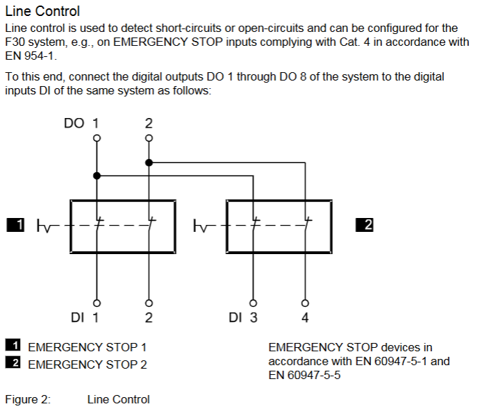
Digital input: 20 non isolated inputs, divided into 5 groups for power supply (4 in each group, LS+is a short-circuit protection 24V power supply), supports "power loss trip" logic (input is in a low-level safety state in case of fault), and can be configured with line control to detect short circuits/open circuits;
Digital output: 8 non isolated outputs, channels 1-3/5-7 have a rated current of 0.5 A (60 ° C), channels 4/8 support 1 A (60 ° C)/2 A (50 ° C), automatically turn off and periodically retry when overloaded, and trigger a fault alarm when short circuited;
Fault response mechanism: When an input/output fault (such as open circuit or output overload) is detected, a single channel fault only cuts off the corresponding channel. If the controller experiences an overall fault, all outputs are cut off, and the FAULT LED is activated and a fault code is reported (such as 0x0001 indicating input module fault and 0x0200 indicating total current exceeding the limit);
Self detection function: supports MOT (maintenance testing) and FTT (fault tolerance time) testing, detecting hardware faults (such as processor abnormalities), software errors (such as cycle time exceeding limits), and triggering output cutoff when overheating occurs (first level overheating code 0x0400, second level overheating code 0x0800).
(2) Hardware Structure and Interface
key parameters
|Storage capacity | Version<6.46:500 kB program/data; Version ≥ 7:1023 kB program/data; Version 6.100:2047 kB Program/Data | Adapt to User Programs of Different Complexity|
|Response time | ≥ 20 ms | Meet the real-time requirements of small and medium-sized security applications|
|Communication interface | 4 x RJ-45 (SafeEthernet), 3 x 9-pin D-sub (FB1/FB2/FB3, supports PROFIBUS/RS485, etc.) | Supports secure and standard communication protocols|
|Clock buffer | Integrated gold capacitor, maintains clock for about 1 week after power failure | Ensure time synchronization continuity|
|Dimensions (H × W × D) | 114 × 257 × 66 mm (including fasteners) | Weight approximately 1.2 kg, supporting 35 mm DIN rail installation|
Grouping and meaning of LED indicator lights
There are a total of 5 sets of LEDs on the front end of the controller, which perform a full light test when powered on. The status meanings of each indicator light are as follows:
Working voltage light (24 VDC, green): normally on indicates normal power supply, off indicates no voltage;
System lights (red/yellow, 6 lights):
RUN (green): Constant light indicates normal operation (executing user programs), slow flashing indicates STOP status or loading of operating system;
ERROR (red): Constant light indicates entering the ERROR STOP state (such as hardware failure), slow flashing indicates operating system failure requiring reloading;
ROG (yellow): Constant light indicates loading configuration, slow flashing indicates switching to STOP state or loading operating system;
FORCE (yellow): Constant light indicates that the forced function is activated in RUN state, and slow flashing indicates that it is ready to be forced in STOP state;
FAULT (yellow): Constant light indicates configuration/operating system damage, slow flashing indicates I/O failure;
OSL/BL (yellow): Slow flashing indicates emergency loader activation/boot loader failure;
Communication light (green/yellow next to RJ-45): Green light constantly on indicates full duplex, flashing indicates conflict; A constant yellow light indicates a normal physical connection, while a flashing light indicates data transmission;
I/O light (DI 1-20/DO 1-8, yellow): normally on indicates that the channel is powered on (input valid/output engaged), off indicates that the channel is powered off (safe state);
Fieldbus light (FB1-3, yellow): The status changes with the protocol (such as always on when PROFIBUS communication is normal), please refer to the corresponding communication manual for details.
Reset button function
Reserve a reset hole in the upper left corner of the controller (triggered by an insulating pin), only for scenarios where the administrator account is forgotten or the IP address does not match: when restarting, press and hold the reset button for ≥ 20 seconds to restore the default parameters (IP: 192.168.0.99; SRS: 60000.0.0), and clear the user account (only the default administrator account is retained, password is empty). Attention: Before resetting, all fieldbus plugs must be unplugged to avoid interfering with communication with other devices.
Installation and configuration process
(1) Controller installation and wiring
Installation prerequisites
It needs to be fixed on a 35 mm DIN rail with reserved heat dissipation space around it (power loss of 12-33 W, avoiding close proximity to heating equipment);
Ex Zone 2 installation requires additional requirements: enclosure protection level ≥ IP54 (compliant with EN 60529), enclosure must be labeled with a "power off operation only" warning, equipped with a 10A delay fuse, PELV/SELV power supply, and reference to EN 60079-15 standard (terminal wiring, creepage distance, etc.).
Wiring specifications
Power wiring: Connect the positive terminal of the 24 VDC module to the "LS+" terminal, and the negative terminal to the "L -" terminal. Independent power supply is required to avoid collinearity with the power circuit;
Digital input wiring: 20 inputs are divided into 5 groups, each corresponding to independent "LS+" (sensor power supply) and "L -" (grounding), such as DI 1-4 corresponding to terminals 13 (LS+) -17 (DI4) -18 (L -), supporting passive contacts and active signals (corresponding to "L -" needs to be connected);
Digital output wiring: 8 outputs are divided into 2 groups, each corresponding to "LS+" (common terminal) and "L -" (ground). For example, DO 1-4 corresponds to terminals 1 (LS+) -5 (DO4) -6 (L -), channels 4/8 support high loads (2A @ 50 ° C), and inductive loads require parallel freewheeling diodes;
Communication wiring: RJ-45 interface connected to SafeEthernet network, supporting daisy chain topology; The D-sub interface (FB1-3) is connected to a fieldbus (such as PROFIBUS/RS485) and requires the use of shielded cables (single ended grounding of the shielding layer to reduce interference).
(2) Software configuration configuration
SILworX configuration (version ≥ 7)
Core Parameters (Module tab):
Basic parameters: Configure controller name, IP address, subnet mask (default 192.168.0.99), SRS (system rack slot address, default 60000.0.0);
Line monitoring: Set the number of pulse channels (e.g. 1 indicates using DO1 pulse to detect the line), pulse delay (waiting time for line fault detection), and pulse slot (fixed at 3);
Fault monitoring: Enable MOT/FTT testing and read fault codes (such as 0x0010 indicating input short circuit, 0x0002 indicating output safety shutdown fault).
Input channel configuration (DI 20: Channels tab): Assign global variables to each input (DI1-DI20), set pulse channels (such as 1 for receiving DO1 pulses), and monitor single channel faults (such as 0x80 for open circuit);
Output channel configuration (DO 8: Channels tab): Assign global variables to each output (DO1-DO8), set output values (1=power on, 0=power off), and monitor single channel faults (such as 0x02 indicating channel overload).
ELOP II Factory configuration (version<7)
Assign system signals to I/O channels through the "Signal Editor", with configuration parameters similar to SILworX. The core difference lies in the signal mapping method (based on "signal name channel" association rather than variable allocation), and the fault code is consistent with the state definition (such as Mod. Error Code 0x0010 indicating configuration error).
Operation, maintenance, and troubleshooting
(1) Daily operation and diagnosis
operation monitoring
Real time status can be viewed through LED: the RUN light is always on to indicate normal operation, the ERROR/AULT light is on to indicate a fault, and the I/O light corresponds to the channel status;
Detailed diagnosis: Read fault logs (such as line short circuit, output overload) through programming tools, support online viewing of I/O feedback values (ensure that instructions are consistent with actual status), SOE function records 5000 events (resolution 1ms) for easy fault tracing.
Common faults and solutions
|Fault phenomenon | Possible causes | Troubleshooting steps|
|All outputs are unresponsive (all I/O lights are off) | 1 The controller has not entered the RUN state; 2. The total current exceeds the limit; 3. Power supply failure | 1 Check the status of the RUN light (whether it is RUN); 2. Read DO. Error Code (whether it is 0x0200); 3. Measure the 24 VDC power supply|
|Single input fault (DI light off, fault code 0x80) | 1. Line open circuit; 2. Sensor power supply failure; 3. Pulse channel configuration error | 1 Check the input wiring (for looseness); 2. Measure LS+voltage (whether it is 24V); 3. Confirm that the pulse channel matches the DO configuration|
|Communication interruption (communication light off) | 1 IP address conflict; 2. Cable malfunction; 3. Mismatch of fieldbus protocol | 1 Check if the controller IP and PADT are on the same network segment; 2. Replace the communication cable; 3. Confirm that the fieldbus protocol (such as PROFIBUS slave address) is configured correctly|
(2) Maintenance and Lifecycle Management
regular maintenance
Operating system update: Utilize system downtime to load the latest version of the operating system through programming tools (the controller needs to be in STOP state), and backup the configuration before updating to avoid data loss;
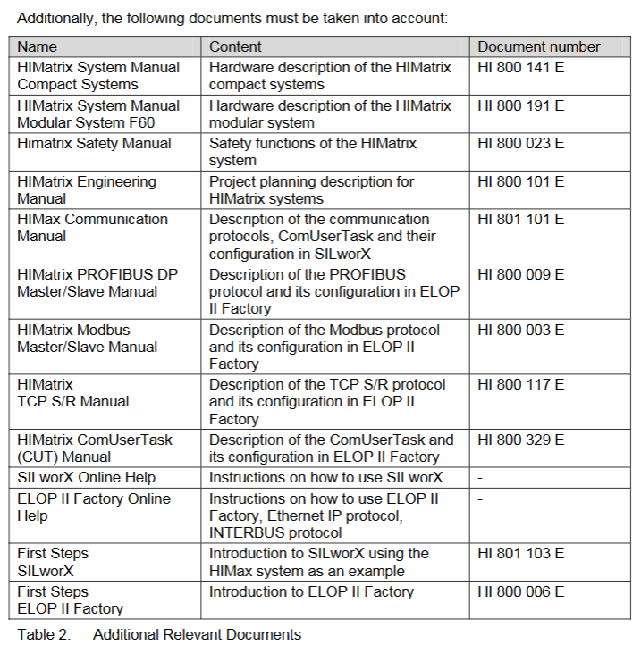
Proof Test: Conducted every 10 years, the test includes I/O channel continuity, line monitoring function, fault response (such as simulating overheating), and communication link integrity. Refer to the HIMA Safety Manual (HI 800 023 E).
Scrap and transportation
Scrap: Industrial users need to dispose of controllers containing electronic components in accordance with environmental protection requirements. They can contact HIMA to sign a scrap agreement, which prohibits the arbitrary disposal of controllers containing electronic components;
Transportation/Storage: Original anti-static packaging should be used to avoid mechanical impact, and the storage temperature should be maintained at -40...+85 ° C to avoid humid environments.
- OMRON
- ABB
- General Electric
- EMERSON
- Honeywell
- HIMA
- ALSTOM
- Rolls-Royce
- MOTOROLA
- Rockwell
- Siemens
- Woodward
- YOKOGAWA
- FOXBORO
- KOLLMORGEN
- MOOG
- KB
- YAMAHA
- BENDER
- TEKTRONIX
- Westinghouse
- AMAT
- AB
- XYCOM
- Yaskawa
- B&R
- Schneider
- KONGSBERG
- NI
- WATLOW
- ProSoft
- SEW
- ADVANCED
- Reliance
- TRICONEX
- METSO
- MAN
- Advantest
- STUDER
- DANAHER MOTION
- Bently
- Galil
- EATON
- MOLEX
- DEIF
- B&W
- ZYGO
- Aerotech
- DANFOSS
- Beijer
- Moxa
- Rexroth
- Johnson
- WAGO
- TOSHIBA
- BMCM
- SMC
- HITACHI
- HIRSCHMANN
- Application field
- XP POWER
- CTI
- TRICON
- STOBER
- Thinklogical
- Horner Automation
- Meggitt
- Fanuc
- Baldor
- SHINKAWA
- Other Brands
- UniOP
- KUKA
- Iba
- Beckhoff
-
 Basler DECS-200-2L Digital Excitation Control
 -
 Basler BE1-47N Voltage Phase Sequence Relay
 -
 Basler AEC63-7 Analog Excitation Controller 220-277V
 -
 Basler BE1-50/51B-107 Overcurrent Relay
 -
 Basler Electric BE1‑32R BE1‑E1P‑BON0F Protective Relay
 -
 Basler BE1-25 Solid State Time Overcurrent Relay M1EA6PA5S1F
 -
 Basler MVC 232 Manual Voltage Control Module 90 37000 103 60VAC 55VDC
 -
 Basler RAL6144-16GM Racer GigE Line Scan Camera
 -
 Basler SSR 63-12 Static Voltage Regulator
 -
 Basler BE1-51A Overcurrent Relay
 -
 Basler BE1-87T Solid State Protective Relay
 -
 Basler SR4A2B01B3A Static Voltage Regulator
 -
 Basler SSR 32-12 Static Voltage Regulator
 -
 Basler TRR00696 Transformer 1KVA 115V
 -
 Basler DECS-100-B15 AVR Replacement
 -
Basler BE1-27 Under-Voltage Relay
-
 Basler ACA2000-50GM Interface Module
 -
 Basler AEC63-7 Analog Excitation Controller
 -
 Basler PRS 250 Veri-Sync Relay
 -
 Basler SR4A-2B15B3A Static Voltage Regulator
 -
Basler BE1-32R Power Relay
-
Basler SR8A-2B06B3E Static Voltage Regulator
-
Basler BE1-81 O/U Frequency Relay
-
 Basler BE1-51A-K2E-W6M-B1N0F Overcurrent Relay
 -
Basler BE1-851 Overcurrent Relay G3A1S1 – 48-125V AC/DC
-
 Basler BEI-51 Overcurrent Relay – NSN 5945-01-293-2363
 -
Basler Electric L301KC Protective Relay – L301KC
-
 Basler DECS-100-B15 Automatic Voltage Regulator – Generator AVR
 -
 Basler SR4A-2B15B3A Static Voltage Regulator – SR4A2B15B3A
 -
 Basler UF 312 Under Frequency Protective Module – 9094700100
 -
Basler Electric MVC 232 Manual Control Module – 60VAC 55VDC 20A
-
Basler PRS 250 Veri-Sync Relay – Generator Synchronizing Relay
-
 Basler DECS-100-A05 Digital Regulator Review
 -
 Basler AEM-2020 Analog Expansion Module Specs
 -
 Basler DECS-100-B15 Digital Excitation Specs
 -
Basler Electric 9125600106 Regulator Component
-
Basler BE1-51A-K1E-W6M-B1N0F Overcurrent Relay
-
 Basler MVC-301 MVC 300 Excitation Controller
 -
 Basler SSR 32-12 Static Voltage Regulator
 -
 Basler 9-2849-00-101 Control Module
 -
Basler BE1-51A Overcurrent Relay
-
 Basler BE1-51/27R Overcurrent Relay
 -
 Basler BE1-51 Overcurrent Relay
 -
 Basler SR8A-2B15B3A Static Voltage Regulator
 -
 Basler BE32965001 Transformer and Timer Board
 -
 Basler 9174700100 EL200-7 Excitation Limiter
 -
 Basler BE2000E AVR Voltage Regulator
 -
Basler BE1-87G Differential Relay
-
 Basler BE21834001 Generator Control Module
 -
Basler DECS-100-B15 AVR
-
 Basler D90 96801 100 PCB Card
 -
 Basler XR2002F Voltage Regulator (110 VAC, 48-480 Hz)
 -
 Basler SR8A-2B14B3A Regulator
 -
 Basler 9561500100 Module
 -
 Basler DECS-400 BE1-11 System
 -
 Basler DECS-100-B15 Excitation Control
 -
 Basler SCP 210 Frequency Controller
 -
Basler SR4A-2B15B3A Static Voltage Regulator
-
Basler BE1-32R Power Relay
-
 Basler PIA2400-17GM Power Interface Adapter
 -
 Basler MVC 232 Manual Voltage Control Module
 -
 Basler SSR 32-12 Static Voltage Regulator
 -
Basler 5MW AVR Generator Voltage Regulator
-
 Basler VR63-4B Voltage Regulator
 -
Basler DECS-100-A05 AVR for Engine Generator
-
Basler DECS-100-B15 Automatic Voltage Regulator
-
Basler BE1-32R Directional Power Relay
-
Basler BE1-87B Differential Relay
-
 Basler UFOV 260A Protective Module
 -
 Basler 9-2614-02-100 PCB Rev M
 -
Basler DECS-100-B15 Digital AVR
-
 Basler 9284900103 PS DECS-400N
 -
 Basler D4N3H1U Intertie Protection
 -
 Basler DECS-100-B15 A15 AVR
 -
 Basler KR4F Voltage Regulator
 -
 Basler BE26434 T14 Transformer
 -
 Basler SR8A-2B15B3A Regulator
 -
 Westinghouse 774B472A12 AR Relay
 -
Basler DECS-100-B15 AVR
-
Basler XR2002F Regulator 110V
-
Basler SR125-E Static Regulator
-
Basler SSR 125-12 Regulator
-
Basler MOC2599 Motor Pot
-
 Basler BE1-DFPR Feeder Relay
 -
 Basler CBS 305 Current Boost
 -
Basler BE1-25 AutoSync
-
Basler MVC 300 Voltage Control
-
 Basler BE3-25A AutoSync
 -
 Basler KR7FF Static Regulator
 -
Basler 90-49000-100 Regulator
-
 Basler 880 kVA Dry Type Transformer Specs
 -
Basler Electric BE1-25 Sync-Check Relay Specs
-
 Basler SSR 125-12 Voltage Regulator Specs
 -
 Basler Electric BE1-851 Overcurrent Relay Review
 -
Basler Electric 149D930G02 Control Sub-Assembly
-
 Basler Electric BE1-81O/UT Frequency Relay Specs
 -
 Basler Electric BE1-51/27C Overcurrent Relay
 -
 Basler Electric 149D956G02 Industrial Component
 -
Basler Electric BE1-51A Overcurrent Relay Specs
-
 Basler Electric BE1-40Q Loss of Excitation Relay
 -
Basler DECS-200 Excitation Control System
-
 Basler DECS-200 Voltage Regulator 56-277V AC / 125V DC
 -
Basler BE1-87T Transformer Differential Relay
-
 Basler RDP-110-S1 Protection Relay
 -
 Basler BE1-700V Digital Protective Relay
 -
 Basler BE1-951 Overcurrent Protection System
 -
 Basler DECS-300 Digital Excitation Control
 -
 Basler DECS-200 Digital Excitation Control
 -
 Basler DECS-200-1C Excitation Control System
 -
Basler DECS-200-1L Digital Excitation Control
-
 Basler Electric BE1-GPS Generator Protection System
 -
Basler Electric DECS-200-1C Digital Excitation Controller
-
 Basler Electric DECS125-15 Excitation Control with Power Module
 -
Basler Electric BE1-87G Differential Relay
-
 Basler Electric BE1-11 Protection System I5A3M2P2N0EA00
 -
Basler Electric DECS-200-1C Excitation Control System
-
Basler Electric BE1-11g Generator Protection Relay
-
Basler Electric DECS 125-15-B2C1 V2.0.9 Excitation Control
-
Basler Electric BE1-81O/UT3ED1JA7N2F Frequency Relay
-
Basler Electric BE1-81O/UT3EE1YB7N1F Frequency Relay
-
 Basler Electric DECS-200-1L Digital Excitation Control System
 -
Basler DECS125-15-B2C1 Excitation Control
-
 Basler 9507900205 SSR Retrofit Voltage Regulator
 -
 Basler BE2000E Digital Voltage Regulator
 -
 Basler BE1-GPS Generator Protection System
 -
Basler DECS-250-CN1CN1N Digital Excitation Control
-
 Basler DGC-2020 Genset Controller
 -
Basler BE1-81O UT3ED1LA7N0F Frequency Relay (Variant)


