
How to install GE IC695CRU320 redundant control unit?
Product Name: Redundant Control Unit, belonging to GE Fanuc RX3i series programmable logic controllers (PLCs). Its core function is to provide dual machine redundant backup for PLC systems, ensuring seamless switching of backup controllers in case of main controller failure and avoiding system shutdown.
Document source: Product specifications and application manual published by NEX Instrument, focusing on hardware parameters, redundant logic, installation configuration, and compatibility instructions.
How to install GE IC695CRU320 redundant control unit?
Product basic information
Product model: IC695CRU320
Product Name: Redundant Control Unit, belonging to GE Fanuc RX3i series programmable logic controllers (PLCs). Its core function is to provide dual machine redundant backup for PLC systems, ensuring seamless switching of backup controllers in case of main controller failure and avoiding system shutdown.
Document source: Product specifications and application manual published by NEX Instrument, focusing on hardware parameters, redundant logic, installation configuration, and compatibility instructions.
Core functions and redundancy principles
(1) Core functions
Dual machine redundant backup
Support two RX3i controllers (such as IC695CPU315/330, etc.) to form a primary and backup architecture, and achieve hardware level redundant control through IC695CPU320.
When the main controller is running normally, the backup controller synchronizes the program, data, and I/O status of the main controller in real time; When the main controller fails (such as power outage or hardware failure), the backup controller switches to the main control mode without disturbance, with a switching time of ≤ 100ms, to ensure continuous production process.
Status monitoring and diagnosis
Built in redundant status indicator lights (such as primary and backup status, synchronization status, fault alarm), visually display the operating status of the redundant system.
Support reading redundant system diagnostic information through RX3i programming software (such as Proficy Machine Edition), including switching reasons, synchronization anomalies, hardware failures, etc., for easy fault location and troubleshooting.
Flexible redundant configuration
Support the "Hot Standby" mode, where both the primary and backup controllers are powered on and running, and the backup devices are in a "ready" state instead of standby mode, improving switching speed.
Can be used with RX3i series I/O modules and communication modules, compatible with redundant I/O architectures (such as IC695RIO remote I/O modules), achieving full system redundancy coverage.
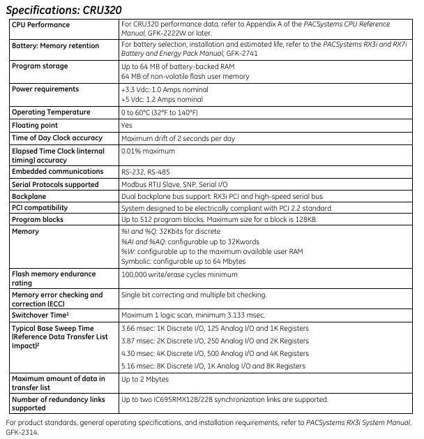
Technical specifications
(1) Hardware parameters
Specification category specific parameters
Power supply requirement input voltage:+5V DC (powered by the RX3i rack backplane, no external independent power supply required); Power consumption: ≤ 5W
Physical dimension width: 40mm (1.57 inches); Height: 100mm (3.94 inches); Depth: 160mm (6.30 inches), compatible with RX3i standard rack (such as IC695CHS012/024)
Working temperature: 0 ° C~60 ° C (operating state); -40 ° C~85 ° C (storage state)
Humidity range 5%~95% RH (non condensing, compliant with IEC 61131-2 environmental standards)
Protection level IP20 (panel installation, to be used in conjunction with control cabinet to prevent dust and liquid intrusion)
(2) Redundancy performance indicators
Performance category indicator requirements
Switching time between primary and backup: ≤ 100ms (from main controller fault detection to backup controller taking over control)
Real time data synchronization in synchronization mode (including program memory, data memory, I/O image area), with a synchronization rate of ≥ 100Mbps
Fault detection range: main controller power failure, CPU hardware failure, memory error, communication link interruption (synchronous link between main and backup)
Redundant links with built-in 2-channel high-speed synchronization interfaces (for data exchange between primary and backup controllers), supporting fiber optic or shielded twisted pair connections
Hardware composition and interfaces
(1) Hardware composition
IC695CRU320 is an independent module structure, with core components including:
Redundant control chip: responsible for determining the primary and backup status, synchronizing logic control, and triggering switching;
Synchronous communication interface: 2 RJ45 or optical ports (depending on configuration), used for data synchronization between the primary and backup controllers;
Status indicator panel: 4 LED indicator lights, meaning as follows:
RUN (green): The redundant unit is running normally;
MASTER (red): The currently connected controller is in main control mode;
STANDBY (yellow): The currently connected controller is in standby mode;
Fault (red): Redundant system failure (such as synchronization failure, module hardware error).
(2) Key interfaces
Interface Type Quantity Function Description
One rack backplane interface is inserted into the RX3i standard rack (such as IC695CHS012) and connected to the rack backplane bus to obtain power and exchange data
Two synchronous communication interfaces are connected to the main and backup controllers to achieve real-time data synchronization (supporting maximum transmission distance: 100m twisted pair cable, 2km fiber optic cable)
One reserved RS232 or Ethernet interface (some versions) for diagnostic equipment to read redundant logs
Installation and configuration requirements
(1) Installation conditions
Rack compatibility
Only compatible with RX3i series standard racks, such as IC695CHS012 (12 slots) and IC695CHS024 (24 slots), which need to be installed in the "redundant control unit dedicated slot" of the rack (usually slots 1-2 on the left side of the rack, refer to the rack manual for details).
Controller compatibility
The primary and backup controllers must be RX3i CPU modules of the same model, supporting models including IC695CPU315, IC695CPU330, IC695CPU340, and the CPU firmware version must be consistent (recommended V3.0 and above).
Environmental Requirements
The installation environment should be kept away from strong electromagnetic interference (such as frequency converters, high-power motors), and avoid sudden temperature changes or dusty/humid environments;
Reserve a heat dissipation space of ≥ 50mm around the module to ensure good heat dissipation (without forced air cooling, the ambient temperature does not exceed 55 ° C).
(2) Configuration steps
Hardware Installation
Insert IC695CRU320 into the dedicated slot of RX3i rack and tighten the panel screws;
Connect the synchronization interface between IC695CRU320 and the main and backup controllers using a synchronous cable (twisted pair or fiber optic);
Connect the power supply, I/O module, and communication module separately for the primary and backup controllers (ensuring consistent configuration of primary and backup I/O).
Software configuration (via Proficy Machine Edition)
Create a new RX3i redundancy project, select the "dual machine redundancy" architecture, specify the primary and backup CPU models and IC695CRU320 as redundant control units;
Configure synchronization parameters (such as synchronization rate, timeout) to enable the "automatic switching" function;
Download the program to the main controller, and the software will automatically trigger the synchronization of primary and backup data. After the synchronization is completed, the redundant system will enter the "normal operation" state.

Compatibility and selection suggestions
(1) List of compatible hardware
Example of compatible device types and models
RX3i Controller IC695CPU315 (Compact), IC695CPU330 (Standard), IC695CPU340 (High Performance)
RX3i rack IC695CHS012 (12 slots), IC695CHS024 (24 slots), IC695CHS008 (8 slots, small system)
Redundant I/O modules IC695RIO001 (remote I/O adapter), IC695RIO002 (redundant I/O interface module)
Communication modules IC695ETM001 (Ethernet module), IC695COM001 (RS485 module)
(2) Selection suggestions
Applicable scenarios
Industrial scenarios that require continuous operation, such as chemical production lines, power dispatch systems, water treatment equipment, etc., require a system availability requirement of ≥ 99.99%.
Selection precautions
The primary and backup controllers need to be completely consistent (model, firmware version, memory configuration) to avoid synchronization failure due to hardware differences;
If the system includes remote I/O, redundant I/O modules (such as IC695RIO002) should be used to ensure that the I/O layer also has redundancy capability;
It is recommended to use shielded twisted pair cables (short distance, ≤ 100m) or multimode optical fibers (long distance, ≤ 2km) for synchronous cables to reduce synchronization anomalies caused by interference.
Troubleshooting and Maintenance
(1) Common faults and solutions
Possible causes and solutions for the fault phenomenon
The redundant status light "FAULT" is always on. 1. The synchronization link between the primary and backup controllers is interrupted; 2. The firmware versions of the primary and backup CPUs are inconsistent; 3. CRU module hardware failure: 1. Check the synchronization cable connection and replace the faulty cable; 2. Upgrade the primary and backup CPUs to the same firmware version; 3. Replace the IC695CRU320 module
Primary/backup switching failure: 1. Backup controller data synchronization is not completed; 2. The switch enable is not turned on; 3. Inconsistent I/O configuration: 1. Wait for synchronization to complete (the synchronization light is always on to indicate completion); 2. Enable "automatic switching" in the software; 3. Verify the primary and backup I/O configurations to ensure consistency
The backup controller cannot synchronize. 1. Poor contact of the synchronization interface; 2. Memory error in the main controller; 3. CRU synchronization logic fault 1. Re plug and unplug the synchronization cable, clean the interface; 2. Restart the main controller and check the memory status; 3. Reset CRU module (via software or power off restart)
(2) Daily maintenance suggestions
Regularly (every 3 months) check the redundancy status indicator lights to confirm that the primary and backup are running normally and the synchronization link is normal;
Export redundant system diagnostic logs through Proficy Machine Edition every 6 months to analyze potential risks such as frequent synchronization failures and switching records;
Avoid plugging and unplugging CRU modules or synchronous cables while they are live to prevent hardware damage; When replacing modules, power off first to ensure that the primary and backup controllers are in a "stop" state.
- OMRON
- ABB
- General Electric
- EMERSON
- Honeywell
- HIMA
- ALSTOM
- Rolls-Royce
- MOTOROLA
- Rockwell
- Siemens
- Woodward
- YOKOGAWA
- FOXBORO
- KOLLMORGEN
- MOOG
- KB
- YAMAHA
- BENDER
- TEKTRONIX
- Westinghouse
- AMAT
- AB
- XYCOM
- Yaskawa
- B&R
- Schneider
- KONGSBERG
- NI
- WATLOW
- ProSoft
- SEW
- ADVANCED
- Reliance
- TRICONEX
- METSO
- MAN
- Advantest
- STUDER
- DANAHER MOTION
- Bently
- Galil
- EATON
- MOLEX
- DEIF
- B&W
- ZYGO
- Aerotech
- DANFOSS
- Beijer
- Moxa
- Rexroth
- Johnson
- WAGO
- TOSHIBA
- BMCM
- SMC
- HITACHI
- HIRSCHMANN
- Application field
- XP POWER
- CTI
- TRICON
- STOBER
- Thinklogical
- Horner Automation
- Meggitt
- Fanuc
- Baldor
- SHINKAWA
- Other Brands
- UniOP
- KUKA
- Iba
- Beckhoff
-
 Basler D90 96801 100 PCB Card
 -
 Basler XR2002F Voltage Regulator (110 VAC, 48-480 Hz)
 -
 Basler SR8A-2B14B3A Regulator
 -
 Basler 9561500100 Module
 -
 Basler DECS-400 BE1-11 System
 -
 Basler DECS-100-B15 Excitation Control
 -
 Basler SCP 210 Frequency Controller
 -
 Basler SR4A-2B15B3A Static Voltage Regulator
 -
 Basler BE1-32R Power Relay
 -
 Basler PIA2400-17GM Power Interface Adapter
 -
 Basler MVC 232 Manual Voltage Control Module
 -
 Basler SSR 32-12 Static Voltage Regulator
 -
 Basler 5MW AVR Generator Voltage Regulator
 -
 Basler VR63-4B Voltage Regulator
 -
 Basler DECS-100-A05 AVR for Engine Generator
 -
 Basler DECS-100-B15 Automatic Voltage Regulator
 -
 Basler BE1-32R Directional Power Relay
 -
 Basler BE1-87B Differential Relay
 -
 Basler UFOV 260A Protective Module
 -
 Basler 9-2614-02-100 PCB Rev M
 -
Basler DECS-100-B15 Digital AVR
-
 Basler 9284900103 PS DECS-400N
 -
 Basler D4N3H1U Intertie Protection
 -
 Basler DECS-100-B15 A15 AVR
 -
 Basler KR4F Voltage Regulator
 -
 Basler BE26434 T14 Transformer
 -
 Basler SR8A-2B15B3A Regulator
 -
 Westinghouse 774B472A12 AR Relay
 -
Basler DECS-100-B15 AVR
-
Basler XR2002F Regulator 110V
-
Basler SR125-E Static Regulator
-
 Basler SSR 125-12 Regulator
 -
 Basler MOC2599 Motor Pot
 -
 Basler BE1-DFPR Feeder Relay
 -
 Basler CBS 305 Current Boost
 -
 Basler BE1-25 AutoSync
 -
 Basler MVC 300 Voltage Control
 -
 Basler BE3-25A AutoSync
 -
 Basler KR7FF Static Regulator
 -
 Basler 90-49000-100 Regulator
 -
 Basler 880 kVA Dry Type Transformer Specs
 -
 Basler Electric BE1-25 Sync-Check Relay Specs
 -
 Basler SSR 125-12 Voltage Regulator Specs
 -
 Basler Electric BE1-851 Overcurrent Relay Review
 -
Basler Electric 149D930G02 Control Sub-Assembly
-
 Basler Electric BE1-81O/UT Frequency Relay Specs
 -
 Basler Electric BE1-51/27C Overcurrent Relay
 -
 Basler Electric 149D956G02 Industrial Component
 -
Basler Electric BE1-51A Overcurrent Relay Specs
-
 Basler Electric BE1-40Q Loss of Excitation Relay
 -
 Basler DECS-200 Excitation Control System
 -
 Basler DECS-200 Voltage Regulator 56-277V AC / 125V DC
 -
Basler BE1-87T Transformer Differential Relay
-
 Basler RDP-110-S1 Protection Relay
 -
 Basler BE1-700V Digital Protective Relay
 -
 Basler BE1-951 Overcurrent Protection System
 -
 Basler DECS-300 Digital Excitation Control
 -
 Basler DECS-200 Digital Excitation Control
 -
 Basler DECS-200-1C Excitation Control System
 -
Basler DECS-200-1L Digital Excitation Control
-
 Basler Electric BE1-GPS Generator Protection System
 -
Basler Electric DECS-200-1C Digital Excitation Controller
-
 Basler Electric DECS125-15 Excitation Control with Power Module
 -
 Basler Electric BE1-87G Differential Relay
 -
 Basler Electric BE1-11 Protection System I5A3M2P2N0EA00
 -
Basler Electric DECS-200-1C Excitation Control System
-
Basler Electric BE1-11g Generator Protection Relay
-
Basler Electric DECS 125-15-B2C1 V2.0.9 Excitation Control
-
 Basler Electric BE1-81O/UT3ED1JA7N2F Frequency Relay
 -
Basler Electric BE1-81O/UT3EE1YB7N1F Frequency Relay
-
 Basler Electric DECS-200-1L Digital Excitation Control System
 -
Basler DECS125-15-B2C1 Excitation Control
-
 Basler 9507900205 SSR Retrofit Voltage Regulator
 -
 Basler BE2000E Digital Voltage Regulator
 -
 Basler BE1-GPS Generator Protection System
 -
Basler DECS-250-CN1CN1N Digital Excitation Control
-
 Basler DGC-2020 Genset Controller
 -
 Basler BE1-81O UT3ED1LA7N0F Frequency Relay (Variant)
 -
 Basler BE1-81O UT3EE1YA9S0F Frequency Relay (Variant)
 -
Basler BE1-81O Over/Under Frequency Relay
-
Basler DECS125-15 Digital Excitation Control
-
Basler Electric BE1-951 Overcurrent Protection System
-
 Basler Electric BE1-700V Digital Protective Relay
 -
 Basler Electric APR63-5 Automatic Voltage Regulator
 -
Basler Electric BE1-851 Overcurrent Protection System
-
Basler Electric DECS-250-LN1SN1N Excitation Control
-
 Basler Electric BE1-87T Transformer Differential Relay
 -
Basler Electric DECS-200-1L Excitation Control System
-
 Basler Electric 9310300100 DECS-300 Excitation Control
 -
 Basler Electric SSE-N 125-4.5KW Shunt Exciter Regulator
 -
 Basler Electric DGC-2020HD-5NS1DNSBA Genset Controller
 -
Basler Electric BE1-81-O/UT3EE1JB7N1F Frequency Relay
-
Basler Electric BE1-81T1EE1WA0N1F Frequency Relay
-
 Basler Electric BE1-25M1EA6PN5R1F Sync-Check Relay
 -
 Basler Electric BE1-GPS Generator Protection System
 -
Basler Electric DECS-250-LN1SN1N Excitation Control Rev V
-
 Basler Electric DECS-250-CN2CN1N Excitation Control
 -
Basler Electric BE1-50/51B-207 Overcurrent Relay
-
Basler Electric DECS-300-C0N0 Excitation Control System
-
Basler Electric DECS-200 Digital Excitation Control System
-
Basler Electric DECS-250-LN1CN1N Excitation Unit
-
Basler Electric DECS-250 LN2SA1D Excitation Unit Specs
-
Basler Electric BE1-87T Transformer Relay Review
-
Basler Electric BE1-11 Protection System
-
Basler Electric BE1-GPS100-E4N1H1N Protection System
-
 Allen-Bradley 442G-MABH-R Safety Module
 -
 Beckhoff CX1030-0111 PLC Assembly Profile
 -
 FANUC IC693CPU364 PLC Module
 -
 Orange Denmark Type 200816 220 PLC Specs
 -
 OMRON C200H-SNT31 Sysmac PLC Module
 -
 Allen Bradley 20AB022A3AYNANC0 PowerFlex 70
 -
 OMRON C200HW-PCU01 Position Control Unit
 -
 ABB AO845A-eA Analog Output Module
 -
 OMRON CJ1M-CPU22 CPU Unit
 -
 Allen Bradley 100-E265ED11 Contactor
 -
 Honeywell 51304511-100 Interface Module
 -
 SOLEXY BXF3S0101N0018 Gateway Module
 -
 OMRON CJ2H-CPU65 CPU Unit
 -
 Automation Direct GS2-45P0 AC Drive
 -
 M68-2000 2-Axis Motion CNC Controller
 -
 OMRON CJ1M-CPU11 V3.0 PLC CPU Unit
 -
 OMRON CJ1W-NC413 4-Axis Positioning Controller
 -
 OMRON 3G2A3-PRO16 Programming Console HMI
 -
 Siemens 3VT8440-2AA04-2GA2 Molded Case Circuit Breaker
 -
 Siemens 3RT5045 Contactor Series
 -
 OMRON C200HS-CPU01-E SYSMAC PLC Controller
 -
 OMRON C500-NC103-E Positioning Control Unit
 -
 OMRON CJ1W-TC001 Temperature Control Unit


