
Motorola MVME Series IPMC712/761 I/O Module
Motorola MVME Series IPMC712/761 I/O Module
Basic Information
The installation and user manual for the Motorola MVME series IPMC712/761 I/O module introduces two multifunctional I/O modules based on the PMC (PCI Mezzanine Card) specification. The core is positioned as an extension component for MVME5100, MVME5500, and MVME6100 single board computers (SBC), providing industrial grade I/O interfaces such as SCSI, serial, and parallel, suitable for industrial control, embedded computing, and other scenarios, especially supporting backward compatibility with the old MVME761/MVME712M modules.
Module core functions and model differences
(1) Core functional positioning
IPMC712 and IPMC761 are both single width standard PMC modules, with the core function of expanding the host's I/O interface capabilities to meet the connection requirements of multiple types of devices in industrial scenarios. The common functions include:
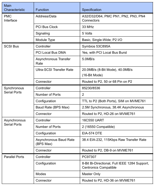
SCSI interface: Integrated LSI SYM53C895A controller, supports Ultra Wide SCSI (16 bit bus), synchronous transfer rate up to 40MB/s (16 bit mode), 20MB/s (8-bit mode), asynchronous transfer rate 5MB/s, suitable for industrial storage devices such as hard drives and optical drives;
Serial Communication: Equipped with Z85230 ESCC (Enhanced Serial Communication Controller) and PC97307 Super I/O chip, providing multi-channel serial ports, supporting asynchronous/synchronous modes, and adapting to serial devices such as modems and sensors;
Parallel port: Supports IEEE 1284 standard, 8-bit bidirectional communication, compatible with Centronics interface devices (such as industrial printers, data collectors);
PCI-ISA Bridge: The bridge between the PCI bus and ISA bus is achieved through the Winbond W83C554F chip, supporting ISA interrupt and DMA functions to ensure legacy device compatibility;
Data storage: Onboard 256 × 8 serial EEPROM (AT24C02), used to store Vital Product Data (VPD) and record module hardware configuration information.
(2) Core differences between IPMC712 and IPMC761
The two module architectures are consistent, with the main difference being the serial port configuration and physical interface design. The specific differences are as follows:
Comparison dimension IPMC712 IPMC761
Number of serial ports: 3 asynchronous ports+1 configurable (asynchronous/synchronous) port, 2 asynchronous ports+2 configurable (asynchronous/synchronous) ports
Serial clock configuration port 4 can be set with J2/J3/J5 jumper for transmitting and receiving clocks, supporting loop back (J5 jumper). Port 3/4 can only be set with J2/J3 jumper for transmitting and receiving clocks, without loop back function
Ethernet compatibility backboard Ethernet port unavailable (needs to be extended through P2 adapter) Support backboard Ethernet port routing (needs to be coordinated with MVME761 transition module)
Typical application scenarios focus on simple serial communication extensions, such as sensor data acquisition emphasizing multi serial device connections, such as industrial bus gateways and multi node communication
Hardware architecture and key components
(1) Hardware architecture diagram
The module is designed based on the architecture of "PCI bus → bridge chip → functional subsystem", and the core components include:
PCI interface layer: connected to the host PCI bus (32-bit, 33MHz) through P11-P15 connectors, supporting PCI bus arbitration and burst transmission to ensure data transmission efficiency;
Bridge layer: Winbond W83C554F (PIB, PCI-ISA bridge) implements protocol conversion between PCI and ISA bus, supports 8259 interrupt controller and ISA DMA channel;
Functional subsystem:
SCSI subsystem: LSI SYM53C895A controller+40MHz clock, supporting wide bus and high-speed transmission;
Serial subsystem: Z85230 ESCC (2-channel synchronous/asynchronous)+Z8536 CIO (supplementary modem control signal);
Parallel subsystem: PC97307 Super I/O chip, supporting IEEE 1284 mode;
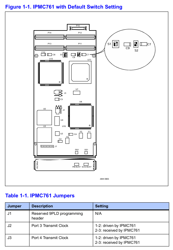
Configuration and Storage: 2 user configurable switches (S1/GPIO configuration, S2/IDSEL selection), AT24C02 EEPROM (VPD storage).
(2) Key electrical parameters
Parameter category specification requirements
Supply voltage+5V (± 5%), ± 12V (± 10%); Typical power consumption:+5V/0.5A,+12V/0.2A, -12V/0.1A; Maximum power consumption:+12V/0.5A, -12V/0.3A
Working temperature 0~70 ℃ (PCB working temperature), storage temperature -40~85 ℃
Isolation and anti-interference support ESD protection (compliant with IEC 61000-4-2), surge protection (IEC 61000-4-5), PCI signal level 5V standard
Connectors P11~P15 (64 pin EIA-E700 connector), supporting PCI interface and I/O signal output
Hardware configuration and installation requirements
(1) Core configuration items
S1 switch (GPIO configuration): 1 × 4 switch, used to set SCSI speed and bus width:
S1-P1(GPIO2):OFF=Ultra SCSI(20/40MB/s),ON=FAST SCSI(10/20MB/s);
S1-P2 (GPO3): OFF=Wide SCSI (16 bits), ON=Narrow SCSI (8 bits);
S1-P3/P4: Not used (NC).
S2 switch (IDSEL selection): 1 × 2 switch, select the IDSEL signal connection of the PCI device according to the host model:
MVME5100/MVME5500: S2-P1=ON, S2-P2=OFF (connected to AD11);
MVME6100: S2-P1=OFF, S2-P2=ON (connected to AD16/AD21);
Prohibit simultaneous ON/OFF of two switches (to avoid abnormal device enumeration).
Jumper configuration:
IPMC712: J1 (reserved programming interface), J2/J3 (port 4 clock source), J5 (clock loop back);
IPMC761: J1 (reserved), J2/J3 (source of clock for port 3/4 transmission and reception).
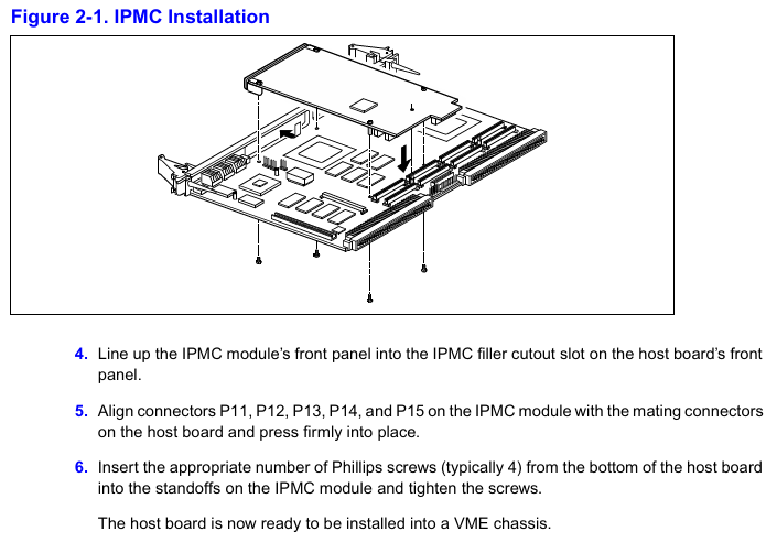
(2) Installation specifications
Installation position: Only supports installation in PMC slot 1 of the host. Before installation, the filler plate of the host front board needs to be removed to ensure that the module front board is aligned with the host front board;
Static protection: An anti-static wristband must be worn, and the module should be stored in anti-static packaging to avoid touching the circuit board pins;
Mechanical fixation: Fix the module on the host bracket with 4 M2 screws, ensuring that connectors P11-P15 are fully engaged with the host socket;
EMI compliance: After installation, ensure that all panel openings of the host are covered by modules or filler boards to avoid electromagnetic interference leakage.
Programming and Compatibility
(1) Core points of programming
PCI device configuration:
The onboard PCI device includes a SCSI controller (vendor ID 0x1000, device ID 0x0012) and a PCI-ISA bridge (vendor ID 0x10A, device ID 0x0565), which require setting interrupt and DMA parameters through the PCI configuration space;
IDSEL address mapping: Ensure device enumeration uniqueness based on the host model corresponding to AD11 (MVME5100/5500) and AD16/AD21 (MVME6100).
Interrupt and DMA configuration:
Interrupt routing: SCSI interrupts (IRQ14) and serial/parallel interrupts (IRQ3/4/7/9/10) are bridged to the host MPIC (Multiprocessor Interrupt Controller) through PIB, with different interrupt pin assignments for different hosts (such as IRQ0/9 for MVME5100 and MPP5/16 for MVME6100);
DMA channels: Supports 7 ISA DMA channels, with channels 0/1/5/6 for serial port transmission and reception, channels 2/3 for parallel ports, and channel 4 for internal cascading.
VPD access: Access the onboard EEPROM (address 0xA4) through the I ² C bus to read configuration information such as module model and hardware version. The host needs to access it through the I ² C controllers of Hawk (MVME5100), GT-64260 (MVME5500), and MV64360 (MVME6100).
(2) System compatibility
Adaptation host: Only supports MVME5100, MVME5500, and MVME6100 single board computers, and S2 switch and interrupt mapping need to be configured according to the host model;
Backward compatibility: Supports replacing old MVME761/MVME712M modules and achieving I/O signal compatibility through P2 transition cables, but attention should be paid to some PMC I/O routing restrictions (such as IPMC712 not supporting backplane Ethernet);
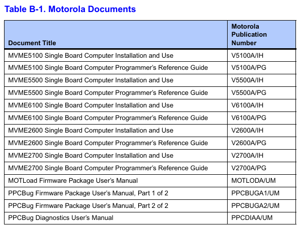
Software support: Compatible with Motorola PowerPlus II architecture programming specifications, requiring the use of firmware tools such as MOTLoad and PPCBug for configuration and debugging.
Environmental adaptability and compliance certification
(1) Environmental parameters
Environmental category specification requirements
Temperature operation: 0~70 ℃ (compliant with IEC 60068-2-1/2); Storage: -40~85 ℃ (compliant with MIL-STD-810G)
Humidity 20%~95% (40 ℃ without condensation, in accordance with IEC 60068-2-78)
Vibration and shock operation vibration: 5~60Hz (0.137mm), 60~150Hz (1.0G, in accordance with IEC 60068-2-6); Storage impact: 15G (11ms, compliant with IEC 60068-2-27)
The protection level module body is IP20 (compliant with IEC 60529) and needs to be installed in control cabinets with a protection level of IP54 or higher
(2) Compliance certification
Electromagnetic compatibility (EMC): compliant with EN 55022 Class B, EN 61000-6-2/4, resistant to ESD (± 8kV air discharge), surge (± 2kV communication port);
Safety certification: CSA ordinary area certification, Class I Division 2 Groups A-D hazardous area (non flammable);
Environmental Compliance: Compliant with RoHS Directive (Restriction of Hazardous Substances) and WEEE Directive (Electronic Waste Recycling).
Precautions for use
SCSI signal conflict: When installing other modules in host PMC slot 2, it is important to note that there may be conflicts with the SCSI signal (P15 connector), and the redundant signal should be disconnected through a 0 Ω resistor (R92-R100);
Clock configuration: The serial port clock source needs to be strictly matched through jumper wires (such as distinguishing between "module driver" or "external input" for IPMC712 port 4 clock) to avoid communication abnormalities;
Firmware and documentation: The module needs to be used in conjunction with the host firmware (such as the Hawk ASIC firmware of MVME5100). It is recommended to refer to the host manual to confirm the details of interrupt and DMA configuration.
- OMRON
- ABB
- General Electric
- EMERSON
- Honeywell
- HIMA
- ALSTOM
- Rolls-Royce
- MOTOROLA
- Rockwell
- Siemens
- Woodward
- YOKOGAWA
- FOXBORO
- KOLLMORGEN
- MOOG
- KB
- YAMAHA
- BENDER
- TEKTRONIX
- Westinghouse
- AMAT
- AB
- XYCOM
- Yaskawa
- B&R
- Schneider
- KONGSBERG
- NI
- WATLOW
- ProSoft
- SEW
- ADVANCED
- Reliance
- TRICONEX
- METSO
- MAN
- Advantest
- STUDER
- DANAHER MOTION
- Bently
- Galil
- EATON
- MOLEX
- DEIF
- B&W
- ZYGO
- Aerotech
- DANFOSS
- Beijer
- Moxa
- Rexroth
- Johnson
- WAGO
- TOSHIBA
- BMCM
- SMC
- HITACHI
- HIRSCHMANN
- Application field
- XP POWER
- CTI
- TRICON
- STOBER
- Thinklogical
- Horner Automation
- Meggitt
- Fanuc
- Baldor
- SHINKAWA
- Other Brands
- UniOP
- KUKA
- Iba
- Beckhoff
-
 OMRON C60H C6DR DE V1 Sysmac PLC
 -
 MITSUBISHI ELECTRIC A2ACPU21 S1 CPU Module
 -
 ABB BAILEY INNPM12 Network Process Module
 -
 HONEYWELL 620 0073C IPC PLC Module
 -
 Mitsubishi 15050 PR02B PLC Circuit Board
 -
 SIEMENS 6SY7000 0AC37 Drive Control Module
 -
 OMRON TJ2 ECT16 Traxial EtherCAT Controller
 -
 GE Fanuc IC698PSD300D Power Supply Module
 -
 Texas Instruments Series 505 16 Position Base
 -
 OMRON YASKAWA SGDH 10DE OY Servo Drive
 -
 Allen‑Bradley 440G-MT Safety Interlock Switch Specs
 -
 Rubycon PD27A 24V 8A Power Supply Module
 -
 SK-H1-GDB1-F11D PLC Gate Driver Board Kit
 -
 VIPA 441-4UA14 451-4UA14 PLC Module Rack
 -
 Mitsubishi FX5U-80MT ESS PLC Controller Specs
 -
 Mitsubishi Q64TCRTN Temperature PLC Module
 -
 GE 1C31170G Rev10 PLC Circuit Board Module
 -
 Schneider TWDLMDA40DTK PLC Controller Module
 -
 Omron FQM1-MMA22 Motion Control Module Specs
 -
 OMRON CJ1W-NCF71 Position Control Unit Specs
 -
 Schneider TSXETY4103 Ethernet Module
 -
 Mitsubishi Q12PHCPU Process CPU
 -
 Yaskawa 3G3HV-A4022-CE AC Drive
 -
 Cincinnati Milacron 3-533-0669G Temperature Control Board
 -
 Allen Bradley 20AC030A3AYNANC0 PowerFlex 70 Drive
 -
 Siemens 6ES7314-6BG03-0AB0 CPU 314C-2 DP
 -
 Carrier 17EX54007903 PLC Module
 -
 OMRON CS1W-V600C12 ID Controller Module
 -
 Honeywell 51402755-100 PCB Card
 -
 Heidenhain ECN 113 Rotary Encoder
 -
 OMRON B7AM-8B16 I/O Terminal Block
 -
 Fanuc A06B-6110-H026 Power Supply Module
 -
 Schneider TSXETG3021 Ethernet Gateway
 -
 OMRON CS1W-CLK21-V1 Controller Link Unit
 -
 NP1W6406T-Z704 PLC I/O Module
 -
 OMRON CJ1W-DA08C Analog Output Module
 -
 Yaskawa 3G3HV-A4022-CE AC Drive
 -
 OMRON NB7W-TW01B CP1L-EL20DR-D Power Panel
 -
 OMRON C500-NC103-E Position Control Unit
 -
 Steag Hamatech PLC DCS Servo Control System
 -
 Siemens 6SN1123-1AA00-0DA1 Power Supply Module
 -
 GE IC693CHS391H CPU & AD693CMM301A PLC Module
 -
 Siemens 6FC5303-0AF23-1AA1 PLC Control Panel
 -
 Square D CM4000T PowerLogic Circuit Monitor J1 F16
 -
 Siemens 6FX5002-5DG10-1BA0 MOTION-CONNECT 500 Cable
 -
 Schmersal SRB324ST 101195504 Safety Relay 24V
 -
 Mitsubishi 15050-PR02A PLC Circuit Board Module
 -
 OMRON CQM1-AD041 Analog Input PLC Module
 -
 Beckhoff EL5042 EtherCAT PLC Terminal Module
 -
 OMRON C200HW-MC402-E Motion Control Unit
 -
 C36TC0UA1100 Industrial Temperature Controller
 -
 NL8048BC24 12 Industrial Control LCD Module
 -
 OMRON R88D Servo Drive and Motor System
 -
 OMRON CS1W CLK21 V1 Controller Link Module
 -
 OMRON YASKAWA R7M A20030 S1 D Servo Motor
 -
 SIEMENS 6AV2128 3KB06 0AX1 Unified Comfort Panel
 -
 Schneider Electric METSEPM8240 PowerLogic Meter
 -
 Advanced AMCI 1PLC 1 31F Programmable Limit Switch
 -
 ABB PM582 ETH Programmable Logic Processor
 -
 SIEMENS 6FC5110 0CB01 0AA0 CPU Control Board
 -
 Schleicher P03GS13A CPU Module
 -
 Siemens 6SN1123-1AA00-0BA1 Power Module
 -
 Mitsubishi A1S61PN Power Supply Module
 -
 Yaskawa CPS-IONB DC Power Supply Module
 -
 Siemens 6ES7215-2BD00 CPU 215-2
 -
 Mitsubishi A2ACPU MELSEC PLC System Kit
 -
 ProSoft 3150-MCM Communication Module
 -
 Mitsubishi OSE104ET Incremental Encoder
 -
 OMRON CJ1W-AD081-V1 Analog Input Module
 -
 Broadcom BCM5464A1KRB Quad Port Ethernet IC
 -
 Modicon M221-24IO TM221C24 PLC 24 PNP Transistor
 -
 Allen-Bradley 1321-3R160-B Line Reactor 3R160B
 -
 Beckhoff CX1020-0012 Embedded PLC Module Specs
 -
 Turck BL20-PF-24VDC-D Power Feed Module Specs
 -
 Siemens 6SY7000-0AC37 Power Supply Module
 -
 Yaskawa SGDH-10DE-OY 1kW 400V Servo Drive Specs
 -
 Omron 3G3SV-BB015-E 1.5kW 220V VFD Specs
 -
 Uni-Pro CPU91-PLC J 23.020167X Processor Module
 -
 PASABAN MTC-3044 PLC Rack Power Supply 4835-A
 -
 XYCOM 3015T Operator Interface Panel BIN4.4.4
 -
 OMRON CJ1W-MD261 Mixed I/O Module
 -
 Omron NJ301-1100 PLC CPU eCat EIP Specs
 -
 Omron F500-C15-ETN Vision System PLC Module
 -
 Modicon M241-24IO TM/T2UK PLC with Ethernet
 -
 SIXNET YS-800-001 RTU PLC Module
 -
 BEMAC UST-202-D Interface Board 1307D V08B2
 -
 Yaskawa JANCD-MMOIC-02 Drive Circuit Board
 -
 ABB 3BSE005028R1 SDCS-COM-1 Comm Board
 -
 Omron 3G3MX2-A4110 A4150 Inverter Drives Specs
 -
 KEYENCE CA-E100 PLC Module
 -
 GE IC693ALG223-GB Analog Input Module Specs
 -
 ABB BAILEY IMMFP01 Multi Function Processor System
 -
 SIEMENS 6FC5372 0AA00 0AA1 NCU 7202 Controller
 -
Modicon TM241CE4 40I O Transistor Programmable Controller
-
 SIEMENS 6ES7 315 2EH13 0AB0 CPU 3152 PN DP
 -
 NORIS A1 91 PCB Card Rack Module System
 -
 SIEMENS 6ES7 313 5BE01 0AB0 Compact CPU
 -
 SCHNEIDER ELECTRIC S144B MICROLOGIC 60A Trip Unit
 -
 CNI PLC269 v3 Control Module Board Rev H
 -
ABB BAILEY IIMCP02 Processor Module
-
 OMRON NT20S ST121 EV3 Operator Interface Terminal
 -
 OMRON NS-CA001 Video Input Unit
 -
 GE Fanuc IC695CHS012 RX3i Backplane
 -
 Allen Bradley 2711E-K14C6 PanelView 1400e Terminal
 -
 Siemens Sinamics CCB 10000432.71 Power Cell
 -
 Siemens 6SL3210-1SE21-8UA0 Power Module PM340
 -
 Yaskawa CIMR-F7A20P4 AC Drive
 -
 Beckhoff EP1918-0002 EtherCAT Box I/O Module
 -
 OMRON CQM1-TC001 Temperature Control Module
 -
 GE Fanuc SGHA36AT0400 Industrial Contactor
 -
 OMRON NJ501-1500 PLC Machine Automation Controller
 -
 Mitsubishi MAZAK QX084 Power Supply MELDAS 500 CNC
 -
 B&R 0AC808.9 PLC Automation Module
 -
 OMRON CP1H-XA40DT1-D PLC Module
 -
 G&W Electric PLC15 5111 011 15kV Capnut Assembly
 -
 GE DS200SLCCG3AGH PCB Circuit Board
 -
 Siemens SINUMERIK 6FC3981-4FD PLC Extension
 -
 OMRON F300-DC I/O Image Processing Unit
 -
 FANUC A06B-0314-B002 AC Servo Motor
 -
 GC-S84 Programmable Controller Logic Module
 -
 PASABAN MONTELEC MTC3001-DC Drive Control PLC
 -
 Allen Bradley 100E460EJ11 Auxiliary Contactor
 -
 Bosch Rexroth 1070075337-101 Card Parameters
 -
 HMS Anybus AB7646-F Gateway Specifications
 -
 Bosch 062633-303401 CNC Servo PLC Card
 -
 TI 500-5023 Series PLC Power Supply
 -
 Siemens C98043-A7002-L1-12 Circuit Board
 -
 Omron E5CC-RX3A5M-000 Controller


