
SMC IRV10/20 series vacuum regulator
SMC IRV10/20 series vacuum regulator
Product Overview
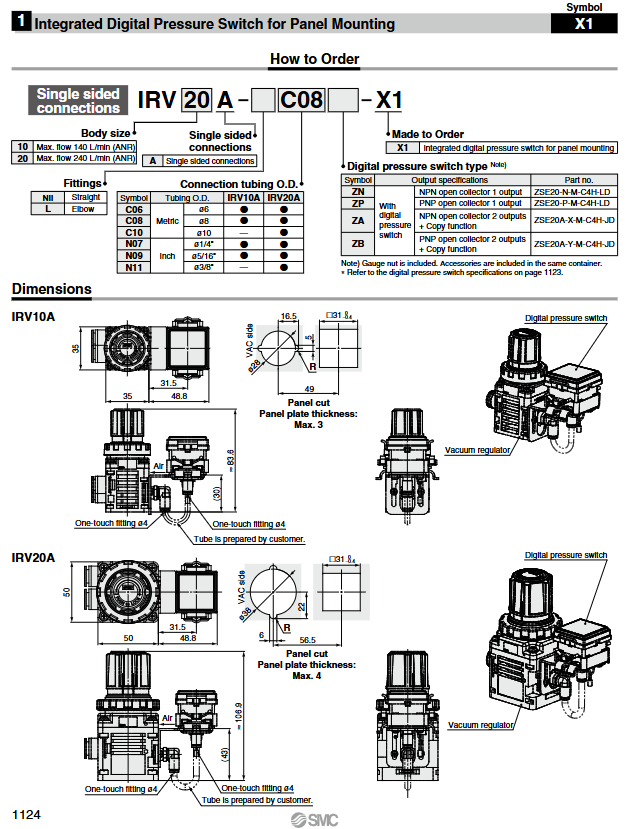
Brand and positioning: The IRV10/20 series vacuum regulator launched by SMC is positioned as a precise pressure control equipment for industrial vacuum systems, with three major advantages of high flow rate, lightweight, and flexible installation. It is suitable for vacuum adsorption, leak testing, and other scenarios. It is an upgraded version of the previous generation IRV1000/2000 series, with a weight reduction of 20% and a flow rate increase of over 2 times.
Series division:
|Model category | Core identification | Maximum flow rate | Connection method | Suitable pipe diameter range|
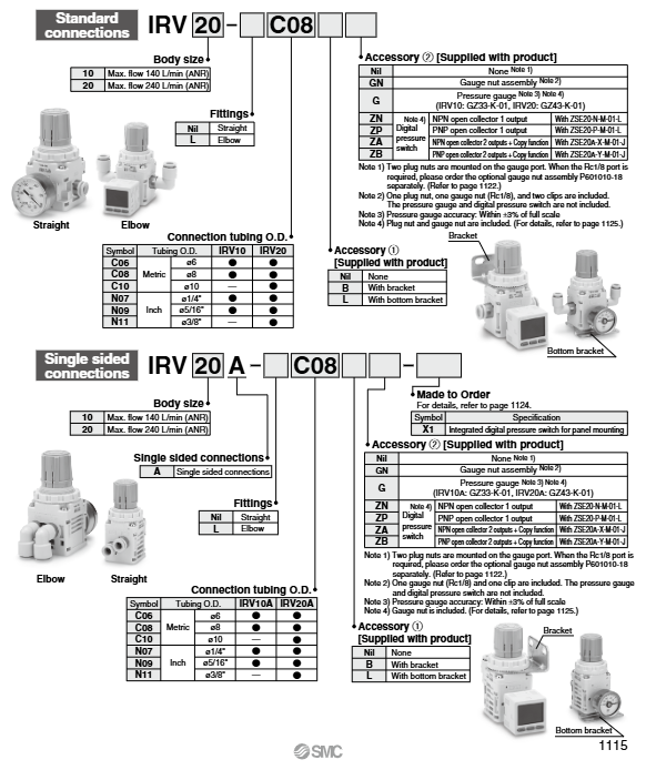
|Basic | IRV10 | 140 L/min (ANR) | Standard Connection | Metric ø 6/8mm; Imperial ø 1/4 "/5/16"|
|Basic | IRV20 | 240 L/min (ANR) | Standard Connection | Metric ø 6/8/10mm; Imperial ø 1/4 "/5/16"/3/8 "|
|Unilateral Connection | IRV10A | 140 L/min (ANR) | Unilateral Connection | Same as IRV10|
|Unilateral Connection | IRV20A | 240 L/min (ANR) | Unilateral Connection | Same as IRV20|
Core technical parameters
Parameter category specific specifications
Suitable for fluid air
Set pressure range -100~-1.3kPa (affected by vacuum pump side pressure)
Pressure resistance level 100kPa (without pressure gauge); Prohibit positive pressure for models with pressure gauges
Atmospheric inhalation gas consumption ≤ 0.6 L/min (ANR)
Environment and fluid temperature 5~60 ℃
Knob resolution ≤ 0.13kPa
Weight (without accessories) IRV10-C08:135g; IRV10A-C08:125g; IRV20-C10:250g; IRV20A-C10:250g
Core configuration and expansion accessories
Connection and installation accessories
Quick change connector: Built in straight/curved quick change connector, IRV10 (A) compatible with VVQ1000 series, IRV20 (A) compatible with VVQ2000 series, supports switching between straight (Nil logo) and curved (L/L1 logo).
Installation bracket: Optional ordinary bracket (B label), bottom bracket (L label), IRV10 (A) bracket model P601010-17, IRV20 (A) bracket model P601020-17; The bottom bracket includes the bracket body, 4 square nuts, and 4 cross screws. The tightening torque of the screws is: IRV10 (A) (M3) 0.32 ± 0.03 N · m, IRV20 (A) (M4) 0.76 ± 0.05 N · m.
Sealing and connection accessories: plug nut assembly (P601010-11, sealing idle pressure gauge interface), pressure gauge nut assembly (P601010-18, connecting pressure gauge/pressure switch, Rc1/8 interface).
Pressure monitoring accessories
Pressure gauge:
|Model | Compatible host | Measurement range | Accuracy | Dial size|
|GZ33-K-01 | IRV10/10A | -100~0kPa | ± 3% full-scale | ø 30mm|
|GZ43-K-01 | IRV20/20A | -100~0kPa | ± 3% full-scale | ø 43mm|
Digital pressure switch (ZSE20 series):
|Identification | Output Specification | Supporting Model | Functional Features|
|ZN | NPN collector open circuit 1 output | ZSE20-N-M-01-L | Lead length 2m, with connector|
|ZP | PNP collector open circuit 1 output | ZSE20-P-M-01-L | Lead length 2m, with connector|
|ZA | NPN collector open circuit 2 output+replication function | ZSE20A-X-M-01-J | Lead length 2m, with connector|
|ZB | PNP collector open circuit 2 output+copy function | ZSE20A-Y-M-01-J | Lead length 2m, with connector|
Core parameters: applicable pressure range 0.0~-101.0kPa, minimum set increment 0.1kPa, power supply 12-24VDC, current consumption ≤ 35mA, maximum load current 80mA.
Working principle and structural design
Working Principle:
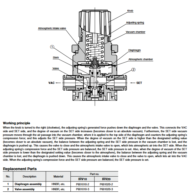
Pressure regulation: Rotate the knob clockwise, adjust the spring to push the diaphragm and valve, connect the VAC side (vacuum pump) and SET side (load), and increase the vacuum degree on the SET side; The pressure on the SET side is transmitted to the vacuum chamber through the airway and balanced with the spring force to achieve pressure stability.
Pressure compensation: When the vacuum degree on the SET side is higher than the set value, the diaphragm moves upward, the valve closes, and the atmospheric suction valve opens to supplement the atmosphere and reduce the vacuum degree; When the vacuum degree on the SET side is lower than the set value, the diaphragm moves down, the atmospheric suction valve closes, and the valve opens to increase the vacuum degree.
Structural design:
Core components: knob (with locking function, press the hidden orange ring to lock), regulating spring, atmospheric suction valve, vacuum chamber, diaphragm, valve stem, valve.
Fixed method: The pressure gauge/digital pressure switch is fixed with a clip buckle. When disassembling, the clip must be removed first, and pressure operation is prohibited; The quick change connector is designed in a cartridge style and secured with a clip. To replace it, a Phillips screwdriver is needed to remove the clip.
Protective design: Airway aperture ø 2.6mm to avoid blockage; The side air intake holes of the fuselage need to be kept unobstructed, otherwise the pressure cannot be adjusted normally.
Ordering rules and customization options
Standard ordering code structure:
Standard connector: IRV+body size (10/20)+connector type (Nil=straight, L=curved)+pipe diameter symbol (e.g. C08=ø 8mm)+accessory symbol (e.g. G=pressure gauge, ZN=digital pressure switch)+installation accessories (e.g. B=bracket)
Single side connection model: IRV+body size (10/20)+A (single side connection)+joint type+pipe diameter symbol+accessory symbol+installation accessories
Example: IRV20A-L-C08-ZB-B (IRV20 single-sided connection, curved joint, ø 8mm pipe diameter, PNP dual output digital pressure switch, with bracket)
Customization option: Panel installation integrated digital pressure switch (selection symbol X1), please contact SMC to confirm detailed dimensions, specifications, and delivery cycle. The maximum thickness of the compatible panel is 3mm for IRV10A and 4mm for IRV20A.
Installation and usage specifications
Installation points:
Pipeline connection: VAC port connected to vacuum pump, SET port connected to load, reverse connection is prohibited; Attention should be paid to the VAC/SET side direction for single-sided connection models, and the pressure gauge/pressure switch should be inserted in place (with the nut flush with the product surface).
Environmental requirements: Avoid corrosive gases, dust, vibration, direct sunlight, and heat source radiation; The dust environment requires the installation of a vacuum filter or drainage separator at the SET port.
Pressure limit: The model with a pressure gauge is prohibited from using positive pressure, otherwise it may damage the pressure gauge; The flow rate of the vacuum pump needs to be matched, and when the flow rate is insufficient, an air storage tank can be added on the VAC side.
Operation taboos:
When under pressure, it is forbidden to disassemble the screws, valve guides, or pressure gauges/switches of the machine body. The set pressure should be adjusted to 0 (atmospheric pressure) first and the vacuum pump should be turned off.
Do not block the side air inlet of the aircraft; When inserting the curved quick change connector into the pipeline, the connector should be held by hand to avoid leakage or damage caused by force.
Maintenance instructions:
Vulnerable parts: diaphragm components (IRV10: P6010-2; IRV20: P601020-2), valve components (IRV10: P6010-3; IRV20: P601020-3), all made of materials such as HNBR.
Cleaning requirements: Use only non corrosive cleaning agents for wiping, and do not use solvent based products.
- OMRON
- ABB
- General Electric
- EMERSON
- Honeywell
- HIMA
- ALSTOM
- Rolls-Royce
- MOTOROLA
- Rockwell
- Siemens
- Woodward
- YOKOGAWA
- FOXBORO
- KOLLMORGEN
- MOOG
- KB
- YAMAHA
- BENDER
- TEKTRONIX
- Westinghouse
- AMAT
- AB
- XYCOM
- Yaskawa
- B&R
- Schneider
- KONGSBERG
- NI
- WATLOW
- ProSoft
- SEW
- ADVANCED
- Reliance
- TRICONEX
- METSO
- MAN
- Advantest
- STUDER
- DANAHER MOTION
- Bently
- Galil
- EATON
- MOLEX
- DEIF
- B&W
- ZYGO
- Aerotech
- DANFOSS
- Beijer
- Moxa
- Rexroth
- Johnson
- WAGO
- TOSHIBA
- BMCM
- SMC
- HITACHI
- HIRSCHMANN
- Application field
- XP POWER
- CTI
- TRICON
- STOBER
- Thinklogical
- Horner Automation
- Meggitt
- Fanuc
- Baldor
- SHINKAWA
- Other Brands
- UniOP
- KUKA
- Iba
- Beckhoff
-
 OMRON C60H C6DR DE V1 Sysmac PLC
 -
 MITSUBISHI ELECTRIC A2ACPU21 S1 CPU Module
 -
 ABB BAILEY INNPM12 Network Process Module
 -
 HONEYWELL 620 0073C IPC PLC Module
 -
 Mitsubishi 15050 PR02B PLC Circuit Board
 -
 SIEMENS 6SY7000 0AC37 Drive Control Module
 -
 OMRON TJ2 ECT16 Traxial EtherCAT Controller
 -
 GE Fanuc IC698PSD300D Power Supply Module
 -
 Texas Instruments Series 505 16 Position Base
 -
 OMRON YASKAWA SGDH 10DE OY Servo Drive
 -
 Allen‑Bradley 440G-MT Safety Interlock Switch Specs
 -
 Rubycon PD27A 24V 8A Power Supply Module
 -
 SK-H1-GDB1-F11D PLC Gate Driver Board Kit
 -
 VIPA 441-4UA14 451-4UA14 PLC Module Rack
 -
 Mitsubishi FX5U-80MT ESS PLC Controller Specs
 -
 Mitsubishi Q64TCRTN Temperature PLC Module
 -
 GE 1C31170G Rev10 PLC Circuit Board Module
 -
 Schneider TWDLMDA40DTK PLC Controller Module
 -
 Omron FQM1-MMA22 Motion Control Module Specs
 -
 OMRON CJ1W-NCF71 Position Control Unit Specs
 -
 Schneider TSXETY4103 Ethernet Module
 -
 Mitsubishi Q12PHCPU Process CPU
 -
 Yaskawa 3G3HV-A4022-CE AC Drive
 -
 Cincinnati Milacron 3-533-0669G Temperature Control Board
 -
 Allen Bradley 20AC030A3AYNANC0 PowerFlex 70 Drive
 -
 Siemens 6ES7314-6BG03-0AB0 CPU 314C-2 DP
 -
 Carrier 17EX54007903 PLC Module
 -
 OMRON CS1W-V600C12 ID Controller Module
 -
 Honeywell 51402755-100 PCB Card
 -
 Heidenhain ECN 113 Rotary Encoder
 -
 OMRON B7AM-8B16 I/O Terminal Block
 -
 Fanuc A06B-6110-H026 Power Supply Module
 -
 Schneider TSXETG3021 Ethernet Gateway
 -
 OMRON CS1W-CLK21-V1 Controller Link Unit
 -
 NP1W6406T-Z704 PLC I/O Module
 -
 OMRON CJ1W-DA08C Analog Output Module
 -
 Yaskawa 3G3HV-A4022-CE AC Drive
 -
 OMRON NB7W-TW01B CP1L-EL20DR-D Power Panel
 -
 OMRON C500-NC103-E Position Control Unit
 -
 Steag Hamatech PLC DCS Servo Control System
 -
 Siemens 6SN1123-1AA00-0DA1 Power Supply Module
 -
 GE IC693CHS391H CPU & AD693CMM301A PLC Module
 -
 Siemens 6FC5303-0AF23-1AA1 PLC Control Panel
 -
 Square D CM4000T PowerLogic Circuit Monitor J1 F16
 -
 Siemens 6FX5002-5DG10-1BA0 MOTION-CONNECT 500 Cable
 -
 Schmersal SRB324ST 101195504 Safety Relay 24V
 -
 Mitsubishi 15050-PR02A PLC Circuit Board Module
 -
 OMRON CQM1-AD041 Analog Input PLC Module
 -
 Beckhoff EL5042 EtherCAT PLC Terminal Module
 -
 OMRON C200HW-MC402-E Motion Control Unit
 -
 C36TC0UA1100 Industrial Temperature Controller
 -
 NL8048BC24 12 Industrial Control LCD Module
 -
 OMRON R88D Servo Drive and Motor System
 -
 OMRON CS1W CLK21 V1 Controller Link Module
 -
 OMRON YASKAWA R7M A20030 S1 D Servo Motor
 -
 SIEMENS 6AV2128 3KB06 0AX1 Unified Comfort Panel
 -
 Schneider Electric METSEPM8240 PowerLogic Meter
 -
 Advanced AMCI 1PLC 1 31F Programmable Limit Switch
 -
 ABB PM582 ETH Programmable Logic Processor
 -
 SIEMENS 6FC5110 0CB01 0AA0 CPU Control Board
 -
 Schleicher P03GS13A CPU Module
 -
 Siemens 6SN1123-1AA00-0BA1 Power Module
 -
 Mitsubishi A1S61PN Power Supply Module
 -
 Yaskawa CPS-IONB DC Power Supply Module
 -
 Siemens 6ES7215-2BD00 CPU 215-2
 -
 Mitsubishi A2ACPU MELSEC PLC System Kit
 -
 ProSoft 3150-MCM Communication Module
 -
 Mitsubishi OSE104ET Incremental Encoder
 -
 OMRON CJ1W-AD081-V1 Analog Input Module
 -
 Broadcom BCM5464A1KRB Quad Port Ethernet IC
 -
 Modicon M221-24IO TM221C24 PLC 24 PNP Transistor
 -
 Allen-Bradley 1321-3R160-B Line Reactor 3R160B
 -
 Beckhoff CX1020-0012 Embedded PLC Module Specs
 -
 Turck BL20-PF-24VDC-D Power Feed Module Specs
 -
 Siemens 6SY7000-0AC37 Power Supply Module
 -
 Yaskawa SGDH-10DE-OY 1kW 400V Servo Drive Specs
 -
 Omron 3G3SV-BB015-E 1.5kW 220V VFD Specs
 -
 Uni-Pro CPU91-PLC J 23.020167X Processor Module
 -
 PASABAN MTC-3044 PLC Rack Power Supply 4835-A
 -
 XYCOM 3015T Operator Interface Panel BIN4.4.4
 -
 OMRON CJ1W-MD261 Mixed I/O Module
 -
 Omron NJ301-1100 PLC CPU eCat EIP Specs
 -
 Omron F500-C15-ETN Vision System PLC Module
 -
 Modicon M241-24IO TM/T2UK PLC with Ethernet
 -
 SIXNET YS-800-001 RTU PLC Module
 -
 BEMAC UST-202-D Interface Board 1307D V08B2
 -
 Yaskawa JANCD-MMOIC-02 Drive Circuit Board
 -
 ABB 3BSE005028R1 SDCS-COM-1 Comm Board
 -
 Omron 3G3MX2-A4110 A4150 Inverter Drives Specs
 -
 KEYENCE CA-E100 PLC Module
 -
 GE IC693ALG223-GB Analog Input Module Specs
 -
 ABB BAILEY IMMFP01 Multi Function Processor System
 -
 SIEMENS 6FC5372 0AA00 0AA1 NCU 7202 Controller
 -
Modicon TM241CE4 40I O Transistor Programmable Controller
-
 SIEMENS 6ES7 315 2EH13 0AB0 CPU 3152 PN DP
 -
 NORIS A1 91 PCB Card Rack Module System
 -
 SIEMENS 6ES7 313 5BE01 0AB0 Compact CPU
 -
 SCHNEIDER ELECTRIC S144B MICROLOGIC 60A Trip Unit
 -
 CNI PLC269 v3 Control Module Board Rev H
 -
ABB BAILEY IIMCP02 Processor Module
-
 OMRON NT20S ST121 EV3 Operator Interface Terminal
 -
 OMRON NS-CA001 Video Input Unit
 -
 GE Fanuc IC695CHS012 RX3i Backplane
 -
 Allen Bradley 2711E-K14C6 PanelView 1400e Terminal
 -
 Siemens Sinamics CCB 10000432.71 Power Cell
 -
 Siemens 6SL3210-1SE21-8UA0 Power Module PM340
 -
 Yaskawa CIMR-F7A20P4 AC Drive
 -
 Beckhoff EP1918-0002 EtherCAT Box I/O Module
 -
 OMRON CQM1-TC001 Temperature Control Module
 -
 GE Fanuc SGHA36AT0400 Industrial Contactor
 -
 OMRON NJ501-1500 PLC Machine Automation Controller
 -
 Mitsubishi MAZAK QX084 Power Supply MELDAS 500 CNC
 -
 B&R 0AC808.9 PLC Automation Module
 -
 OMRON CP1H-XA40DT1-D PLC Module
 -
 G&W Electric PLC15 5111 011 15kV Capnut Assembly
 -
 GE DS200SLCCG3AGH PCB Circuit Board
 -
 Siemens SINUMERIK 6FC3981-4FD PLC Extension
 -
 OMRON F300-DC I/O Image Processing Unit
 -
 FANUC A06B-0314-B002 AC Servo Motor
 -
 GC-S84 Programmable Controller Logic Module
 -
 PASABAN MONTELEC MTC3001-DC Drive Control PLC
 -
 Allen Bradley 100E460EJ11 Auxiliary Contactor
 -
 Bosch Rexroth 1070075337-101 Card Parameters
 -
 HMS Anybus AB7646-F Gateway Specifications
 -
 Bosch 062633-303401 CNC Servo PLC Card
 -
 TI 500-5023 Series PLC Power Supply
 -
 Siemens C98043-A7002-L1-12 Circuit Board
 -
 Omron E5CC-RX3A5M-000 Controller


