
TEKTRONIX MSO5000B, DPO5000B series mixed signal oscilloscope
TEKTRONIX MSO5000B, DPO5000B series mixed signal oscilloscope
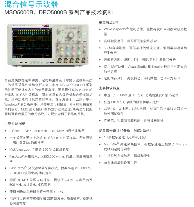
The current design of faster data rates and smaller timing margins requires oscilloscopes to have outstanding signal acquisition performance and analysis capabilities. The Tektronix MSO/DPO5000B series oscilloscopes not only have outstanding signal fidelity, but also provide bandwidth of up to 2 GHz and a sampling rate of 10 GS/s. They also have advanced analysis and mathematical operation functions, which can be enjoyed at any time. Can run Windows based on oscilloscope ® The analysis software. Simply click on the visual trigger to easily capture complex signals. The MSO model includes 16 digital timing channels, and all models can decode common serial protocols, making it easy for you to fully understand your system.
Main Characteristics Analysis
Wave inspector ® Control function, easy navigation and automatic search for waveform count
according to
Advanced trigger kit, standard with visual trigger and search
53 automatic measurements, with optional filtering functions, waveform mathematical operations, and
FFT analysis
Waveform histogram, eye diagram, TIE (jitter/timing) measurement and analysis
Using MATLAB, Visual Studio, and Excel for user-defined tasks
mathematical operations
Optional memory analysis, advanced jitter, serial data, power, and broadband RF
Main protocol features
Trigger and decoding options for medium speed (100 Mb/s to 1 Gb/s) bus
Trigger and decoding options for low-speed (10 Mb/s) bus
USB2.0、 One of Ethernet, USB power supply, MOST, and automotive Ethernet
Sexual testing options
Template testing on communication, computing, and video standards
Mixed Signal Design and Analysis (MSO Series)
16 digital channels (user upgradable)
MagniVu ™ High speed acquisition technology provides 60.6 ps on the digital channel
Fine timing resolution
Parallel bus automatic triggering, decoding, and searching
Set separate thresholds for each channel
Main performance indicators
Four bandwidth models: 2 GHz, 1 GHz, 500 MHz, and 350 MHz
Real time sampling rate of up to 10 GS/s on one or two channels, all channels
Up to 5 GS/s sampling rate
MultiView zoom ™ Up to 250 M point recording length
FastAcq ® Acquisition technology, maximum waveform capture speed>250000 wfm/s
rate
FastFrame ™ Segmented memory acquisition mode with up to 290000 segments,
>310000 waveform/second capture rate
Standard 10 M Ω passive voltage probe, providing<4 pF capacitor load and
500 MHz or 1 GHz analog bandwidth
Vertical resolution>11 bits when using HiRes sampling
Users can choose bandwidth limits and DSP filters to reduce noise and improve efficiency
Frequency measurement accuracy
Core performance parameters (universal across the entire series)
1. Key parameters of simulation channel
Parameter category specification details
Bandwidth range: 100MHz, 150MHz, 350MHz, 500MHz, 1GHz, 2GHz (different models correspond to different bandwidths)
Sampling rate: all channels are turned on simultaneously: 2.5GS/s; Half channel open (e.g. 4-channel model with 2-channel open): 5GS/s (interpolated)
Record length for all channels: 400Mpts; Each channel is independent: 100Mpts (supports segmented storage, enhances long signal analysis capabilities)
Vertical resolution 8-bit (standard mode), 12 bit (high-resolution mode, enabled when sampling rate decreases)
Vertical sensitivity 2mV/div-10V/div (1-2-5 sequence, DC coupling); 10mV/div-10V/div (AC coupling, ≤ 10Hz)
The highest waveform capture rate is 1000000 waveforms per second (in sequence acquisition mode); Normal mode: 50000 waveforms per second
2. Digital channel parameters (only MSO5000B series)
Number of channels: 16 (in conjunction with TPP0816 digital probe);
Timing resolution: 62.5ps (high timing accuracy, suitable for high-speed digital signal timing analysis);
Threshold range: 0.8V-5.5V (supporting various logic level standards such as TTL and CMOS);
Triggering and analysis: Supports parallel bus triggering (such as 8/16 bit data bus), establishing/maintaining violation detection.
3. Time base and trigger parameters
Time base range: 500fs/div-1000s/div (1-2-5 sequence, covering from high-speed signals to slow changing signals);
Trigger types: edge trigger, pulse width trigger, code trigger, Zone trigger (area trigger, only triggers signals within the specified screen area), serial bus trigger (such as I2C address trigger, CAN ID trigger);
Trigger sensitivity: ≤ 10mV when bandwidth ≤ 500MHz (20MHz bandwidth limit enabled); When the bandwidth is greater than 500MHz, ≤ 20mV.
Key functional characteristics
1. Display and operation experience
Display screen: 12.1-inch capacitive touch screen (1280 × 800 resolution), supports multi touch (zoom, pan), adjustable brightness and contrast;
Operation method:
Physical controls: Wave Inspector knob (quick zoom/pan waveform), independent channel control buttons, shortcut keys (AutoSet, Default Setup);
Software features: Multi view display (simultaneously displaying time-domain, frequency-domain, and digital channel waveforms), custom interface (can hide redundant controls);
Interface language: Supports 10 languages including Chinese, English, Japanese, etc., to meet the needs of global users.
2. Collection and analysis functions
(1) Sequence collection
Function definition: Divide long signals into multiple "sequence segments" for acquisition, with each segment recording a length that can be set (such as 1Mpts), and a maximum of 1000 segments in total;
Advantages: Avoiding excessive memory usage for a single long record and capturing burst signals with long intervals (such as 1-second pulse sequences).
(2) Signal analysis
FFT analysis: Supports 1024-1M point FFT, frequency range 0Hz Nyquist frequency, and provides 5 window functions including Hanning/Flattop/Rectangle;
Template testing: Customize waveform templates (such as standard sine wave contours), the oscilloscope automatically compares the collected waveform with the template, marks out out of tolerance areas, and is suitable for batch signal quality testing;
Measurement function: Supports 56 types of automatic measurements (frequency, cycle, peak to peak, rise time, etc.), measurement statistics (average, maximum, minimum, standard deviation), and supports user-defined measurement formulas.
3. Serial bus decoding and triggering
Supports bus types: covering 18 commonly used serial buses, including:
Low speed bus: I2C, SPI, UART (RS-232/422/485), LIN, CAN/CAN FD;
High speed bus: Ethernet (10/100/1000BASE-T), USB 2.0, SATA, PCIe (Gen1/2);
Decoding function: Real time decoding of bus data, displayed in color tags (such as I2C address in yellow and data in blue), supporting viewing of "event table" (displaying timestamp, type, and value of each frame of data);
Trigger function: It can be triggered based on specific bus conditions (such as I2C write address 0x50, CAN ID=0x123) to accurately capture target data frames.
4. Expansion and connectivity capabilities
Built in expansion module:
Function generator: 25MHz output, supporting 14 waveforms including sine wave (0.1Hz-25MHz), square wave (1Hz-25MHz, duty cycle 1% -99%), triangular wave/sawtooth wave (0.1Hz-1MHz), etc;
Logic analyzer: The MSO model has built-in 16 channel logic analysis function, which does not require additional hardware;
Protocol analyzer: supports bus data storage and playback, and can be exported in CSV/Excel format.
External interface:
Data transmission: USB 3.0 (device side, high-speed transmission of waveform data), USB 2.0 (host side, connected to USB flash drive/mouse), Ethernet (10/100/1000BASE-T, supporting LXI-C standard, remote control);
Display output: HDMI (1080P, external monitor);
Synchronization interface: Trigger In/Out (trigger signal input/output), Ext Clock (external clock input);
Storage capacity: Built in 16GB SSD (for storing waveforms/settings/decoding data), supports external USB drives (up to 2TB), and portable hard drives.
Comparison of Parameters for All Series Models (Core Models)
Model Channel Type Bandwidth Sampling Rate (Full Channel/Half Channel) Digital Channel Function Generator Typical Application Scenarios
DPO5104B 4 simulates 100MHz 2.5GS/s/5GS/s without optional basic analog signal debugging (such as power supply)
MSO5104B 4 Analog+16 Digital 100MHz 2.5GS/s/5GS/s 16 Optional Embedded System Mixed Signal Debugging
DPO5154B 4 Analog 150MHz 2.5GS/s/5GS/s No selectable medium speed analog signal (such as 100Mbps communication)
MSO5154B 4 analog+16 digital 150MHz 2.5GS/s/5GS/s 16 optional medium speed mixed signal (such as CAN bus)
DPO5504B 4 Analog 500MHz 2.5GS/s/5GS/s No selectable high-speed analog signal (such as 500MHz clock)
MSO5504B 4 analog+16 digital 500MHz 2.5GS/s/5GS/s 16 optional high-speed mixed signal (such as SPI high-speed communication)
DPO5204B 4 analog 2GHz 2.5GS/s/5GS/s no optional ultra high speed analog signal (such as 1GHz RF)
MSO5204B 4 Analog+16 Digital 2GHz 2.5GS/s/5GS/s 16 Optional Ultra High Speed Mixed Signal (such as PCIe)
DPO5104B-L 4 simulation (low noise) 100MHz 2.5GS/s/5GS No selectable low noise scenarios (such as sensor signals)
Compliance certification
Safety certification: compliant with UL 61010-1, CSA C22.2 No. 61010-1, IEC 61010-1 (overvoltage category II, pollution level 2);
EMC standards: comply with EN 61326-1 (industrial environment), CISPR 11 (Class A, non residential area), FCC Part 15 (Class A);
Environmental requirements: working temperature 0-50 ℃, storage temperature -40-70 ℃, relative humidity 5% -90% (no condensation), altitude ≤ 3000m.
- OMRON
- ABB
- General Electric
- EMERSON
- Honeywell
- HIMA
- ALSTOM
- Rolls-Royce
- MOTOROLA
- Rockwell
- Siemens
- Woodward
- YOKOGAWA
- FOXBORO
- KOLLMORGEN
- MOOG
- KB
- YAMAHA
- BENDER
- TEKTRONIX
- Westinghouse
- AMAT
- AB
- XYCOM
- Yaskawa
- B&R
- Schneider
- KONGSBERG
- NI
- WATLOW
- ProSoft
- SEW
- ADVANCED
- Reliance
- TRICONEX
- METSO
- MAN
- Advantest
- STUDER
- DANAHER MOTION
- Bently
- Galil
- EATON
- MOLEX
- DEIF
- B&W
- ZYGO
- Aerotech
- DANFOSS
- Beijer
- Moxa
- Rexroth
- Johnson
- WAGO
- TOSHIBA
- BMCM
- SMC
- HITACHI
- HIRSCHMANN
- Application field
- XP POWER
- CTI
- TRICON
- STOBER
- Thinklogical
- Horner Automation
- Meggitt
- Fanuc
- Baldor
- SHINKAWA
- Other Brands
- UniOP
- KUKA
- Iba
- Beckhoff
- ADLINK
-
 Atlas Copco QCS-T34025 Quick Connect System
 -
 Atlas Copco HR115-C6-88S Electric Nutrunner
 -
 Atlas Copco 4240031280 PF4 Tool Cable Assembly
 -
 Atlas Copco 3HAB8101-11 Robot Controller Component
 -
 Atlas Copco 1614 6449-00 Regulating Valve
 -
 Atlas Copco 9040120204 Power Box Tool Controller 400VAC
 -
 Atlas Copco 1900100381 Control Panel for Air Compressor
 -
 Atlas Copco TC-4000-P-PB-ES Power MACS Controller Drive
 -
 Atlas Copco 2012-S7-115R Power Focus Torque Controller Tensor S7
 -
 Atlas Copco IRC-Focus-B-C-EIP-HW IRC Focus Controller with Bluetooth
 -
 Atlas Copco LTV 48 R150-HAD Nutrunner Air Wrench
 -
 Atlas Copco TC4000-P-ES Torque Controller 8435651100
 -
Atlas Copco 4240-5008-01 Servo Motor
-
 Atlas Copco 8433-0015-30 Controller Module
 -
 Atlas Copco 3HAB8101-6/07B Servo Driver
 -
 Atlas Copco QST Cable 4220379907
 -
 Atlas Copco 1900071181 Compressor Control Panel
 -
 Atlas Copco 1900071292 Compressor Control Panel
 -
Atlas Copco 2101-S9-115R Tensor S9 Power Focus Controller
-
 Atlas Copco XC2002 Compressor Control Panel 1604951600
 -
Atlas Copco 4240500201 PF4 Interface Cable
-
Atlas Copco PF4 Tool Cable 5M ST 4220 2636 05
-
Atlas Copco PF4 Tool Cable 5M ST 4220 2636 05
-
 Atlas Copco 4240-0366-82 PF4 Tool Cable 5 Meter
 -
 Atlas Copco 4240-0367-81 PF4 Tool Cable with Straight Connector
 -
Atlas Copco 4240-0367-82 PF4 Tool Cable Assembly
-
 Atlas Copco 2101-S9-115R Electric Nutrunner Assembly Tool
 -
Atlas Copco 3HAB8101-7 Control Interface
-
Atlas Copco 3HAB8101-3/07B Control Module
-
 Atlas Copco PF6000 IAM Station Control
 -
 Atlas Copco 8433-0610-04 Selector-4 Controller
 -
 Atlas Copco Power Focus PF4000-C-DN-HW Tool Controller
 -
 Atlas Copco SAM-PA-400-30-E Power Supply Module
 -
 Atlas Copco PF3007-C-H Tensor S4 S7 Torque Controller
 -
Atlas Copco PF4000-C-HW Control System 8433610005
-
 Atlas Copco BSM 2590D R Servo Motor 4230 3012 80
 -
 Atlas Copco 80450.000029 Servo Motor Gear Drive Unit
 -
Atlas Copco 3HAB8101-4/02D Servo Driver DSQC345D
-
Atlas Copco 1900071032 Compressor Control Panel
-
 Atlas Copco 1900520400 Compressor Control Panel
 -
 Atlas Copco Power Focus PF4000-C-EIP-HW Tool Controller
 -
 Atlas Copco PF6000IF 8436180202 Controller
 -
 Atlas Copco 8202900410 Power Supply Unit
 -
 Atlas Copco 4240-0355-80 Interface Module
 -
 Atlas Copco 1089935597 Start Switch Control Panel
 -
 Atlas Copco 1626850003 XC2003 Control Panel
 -
 Atlas Copco STR61-200-20 Angle Wrench
 -
Atlas Copco 1900070123 Power Control Module
-
 Atlas Copco 1089935597 Compressor Control Panel
 -
 Atlas Copco ETP ST32-10-10 Pistol Nutrunner
 -
 Atlas Copco 1900520400 Control Panel Unit
 -
 Atlas Copco 48R050-01001 Relay Module
 -
 Atlas Copco 49-4100-01C5L Power Supply
 -
 Atlas Copco D303-DL-BASIC Controller
 -
 Atlas Copco 8433056445 I/O Expander Error Proofing Module
 -
 Atlas Copco PF4000-G-HW Screwdriver Controller
 -
 Atlas Copco 1202-66270-9325 Cooler Cover Valve
 -
 Atlas Copco EA2-TX-100 Dew Point Sensor
 -
Atlas Copco PF4000-C-HW Controller 240VAC
-
 Atlas Copco 1900 0701 05 Elektronikon Control Panel
 -
 Atlas Copco PF3107-C-HW Tensor 3-7 Controller
 -
 Atlas Copco TPS Control 8202900410 Controller
 -
 Atlas Copco 1900-1005-27 Circuit Board XAS 750
 -
 Atlas Copco Power Focus SL PF4002-C-HW Controller
 -
 Atlas Copco 1900520490 Air Compressor Control Panel
 -
 Atlas Copco QCM2-T-34050 Mass Flow Meter
 -
 Atlas Copco CSS91-B2 Compressor Controller Module
 -
Atlas Copco PF3109-C-DN-HW Industrial Controller
-
 Atlas Copco P1900520060 Air Compressor Controller Gateway
 -
 Atlas Copco Coupling 1635099600 Compressor Part
 -
 Atlas Copco ACTA 4000 Torque Calibrator
 -
Atlas Copco 1626850005 Compressor Control Panel
-
 Atlas Copco DMC50412 Digital Motion Controller
 -
Kontron 2-DH34-0100-03 Atlas Copco SOKO-M@C-IIA-70 HMI 12-24V
-
 Atlas Copco PF3107-G-HW PF3107GHW Controller
 -
 Atlas Copco PF3109-G-DN-HW PF3109GDNHW Controller
 -
 Atlas Copco 8433-2742-00 Power Supply Module
 -
 Atlas Copco 1900-0710-82 Controller Module
 -
 Atlas Copco 9040120204 Industrial Component
 -
 Atlas Copco 2906-0674-00 Zr55-90 8000H Maintenance Kit
 -
 Atlas Copco 1900 0701 23 High Range Regulator for Compressor Controller
 -
 Atlas Copco 4220263610 PF4 Tool Cable 10M ST Cable
 -
 Atlas Copco XC2002 1604951601 Compressor Panel
 -
 Atlas Copco S9 Tensor PF3009-G-DN-HW Controller
 -
 Atlas Copco 80471.000009 Pneumatic Roller Screw Unit
 -
 Atlas Copco 8433710005 PF4000-C-HW Compact Controller Profibus
 -
 Atlas Copco PF4002-G-HW Power Focus Controller
 -
 Atlas Copco 8431038150 Impulse Nutrunner
 -
Atlas Copco PF6000 Power Focus Nutrunner Controller
-
 Atlas Copco 1626850006 Compressor Controller Panel
 -
 Atlas Copco STR61-70-13 Tensor Angle Wrench
 -
Atlas Copco ETV ST61-40-10 Right Angle Electric Screwdriver with Cable
-
 Atlas Copco MK5S Touch Display Controller P1900520400
 -
 Atlas Copco 1900520020 Controller Panel for Compressor
 -
 Atlas Copco SRTT-B 1000Nm-50 Transducer 8059094675
 -
 Atlas Copco ETV ST61-50-10 Right Angle Electric Screwdriver with Cables
 -
 Atlas Copco 4240070100 Power Supply Module
 -
 Atlas Copco TC-52S-I TC52SI Controller
 -
 Atlas Copco ACTA 4000 QC Torque Calibrator
 -
 Atlas Copco 8433 1236 51 ETV S42-10-10 Right Angle Nutrunner
 -
 Atlas Copco ETV STB63-50-B10-BCR-IRCW Tensor STB Right Angle Nutrunner
 -
 Atlas Copco PF6000 SE-10523 Screwdriver Control System
 -
 Atlas Copco Power MACS TC52S 4240 0442 81 Controller
 -
 Atlas Copco 1900071162 Operator Interface Panel
 -
 Atlas Copco 4230-1705-80 I/O Expansion Module
 -
 Atlas Copco 8433 0005 10 Power Supply Module
 -
 Atlas Copco 8433-0020-20 Interface Module
 -
 Atlas Copco TC-4000-S 8435 6500 00 Controller
 -
 Atlas Copco PF4002-C-HW Power Focus SL Controller
 -
 Atlas Copco STanalyser STA-6000 8059095560 Torque Analyzer
 -
 Atlas Copco ComNode 2 Touch 8433271110 Communication Gateway
 -
Atlas Copco PF3000-C-HW Tensor S4 S7 RBU Controller
-
Atlas Copco PPBE0613 24VAC Control Panel
-
Atlas Copco PF3000-C-HW Tensor S4 S7 Controller
-
 Atlas Copco Neos ARC-D130-S+ Inverter Drive
 -
Atlas Copco Power Focus SL PF4002-G-HW Controller
-
 Atlas Copco 8436 6770 00 ILT Base Station
 -
 Atlas Copco 1900520400 Air Compressor Control Panel
 -
 Atlas Copco 1900-0711-51 Display Keypad Unit
 -
 Atlas Copco 1900-0710-52 Communication Control Board
 -
 Atlas Copco 1900-0701-04 Control Interface Module
 -
 Atlas Copco 8092 1143 40 SRTT Transducer 180Nm
 -
 Atlas Copco MT Focus 6000 Controller with Pump and Screwdriver
 -
 Atlas Copco Elektronikon GraphicPlus Controller PPBE0622 PPBE0633
 -
 Atlas Copco PF3109-G-DN-HW Tensor 8-9 Power Focus Nutrunner Control
 -
Atlas Copco Elektronikon P1900520440 Touch Controller
-
 Atlas Copco Power Focus 8 Controller 8436280002
 -
 Atlas Copco 8436 1500 03 FlexCarrier 3-Slot Torque System Component


