
KOLLMORGEN P70360 High Performance Microstep Driver
KOLLMORGEN P70360 High Performance Microstep Driver
Basic Information
Core positioning: P70360 is an AC input micro stepper driver that supports 120/240 VAC power supply, with a maximum output current of 2.5 A RMS (peak 3.5 A RMS) and integrated Dynamic Smooth ™ (Dynamic smoothing) Multi-Stepping ™ (Multi step) Encoderless Stall Detection ™ (No encoder blockage detection) and other patented technologies should be used in conjunction with Kollmorgen recommended stepper motors (such as T2x/N3x/K3x series), and parameter configuration can be achieved through switches or P7000Tools software.
Version iteration: The document has undergone 7 revisions (1-G version), with the latest G version mainly updating outdated pin numbers, adding J4-18 pin warnings, updating brand logos, and revising the motor selection section to ensure compatibility with firmware version 2.10 and above.
Core technical parameters and hardware characteristics of the driver
(1) General Technical Parameters
Category parameter item specification
Power characteristics: Input voltage 120/240 VAC (50/60 Hz), corresponding to DC bus voltage of 320 VDC (optional 160 VDC bus)
Maximum output power 350 W (240 VAC input)
Bus voltage protection undervoltage fault 130 VDC, overvoltage fault 440 VDC, regenerative voltage 420 VDC
Surge current peak 30 A (pulse width 4 ms), recommended slow melting fuse 7 A
Motor adaptation motor inductance range: 320 VDC bus: 50~200 mH; 160 VDC bus: 7~30 mH
The maximum length of motor cable is 20 meters (24 AWG cable)
Step resolution of 200~50000 steps per motor rotation (set through S2-2~S2-4 switches)
I/O Characteristics Step/Direction Input Voltage 2.5~5.5 VDC, Current 5~20 mA, Maximum Frequency 2 MHz, Minimum Pulse Width 250 ns
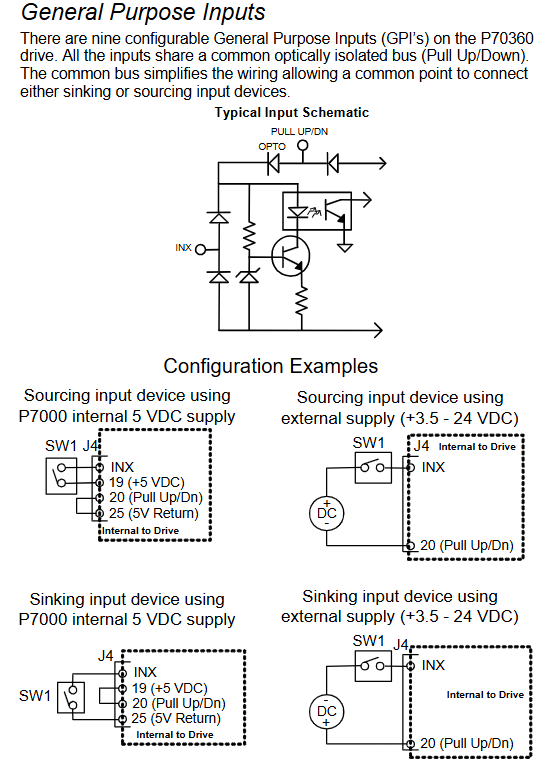
Universal input (9 channels) voltage 3.5~24 VDC, current 10 mA, response time ≤ 250 μ s
Universal output (2 channels) maximum voltage 30 VDC, maximum current 10 mA, response time ≤ 250 μ s
Environmental adaptability working temperature 0~40 ° C
Storage temperature -20~+70 ° C
Humidity 90% relative humidity (no condensation)
Altitude ≤ 1500 m (5000 ft)
Pollution level II
(2) Hardware features and optional configurations
core functionality
Dynamic Smoothing ™): The second-order low-pass filter reduces motion impact and mechanical resonance, and sets the smoothing level (minimum/moderate/severe/aggressive) through S2-8/S2-9 switches.
Encoder less Stall Detection ™): By monitoring the deviation between the instruction position and the actual position through the internal motor model, if the deviation exceeds 2 full steps, a fault will be triggered and activated through the S2-12 switch.
Current Reduction: After the motor is stationary for 100 ms, it automatically reduces the current to 75% of the rated value (the ratio and delay can be adjusted through software), and the S2-10 switch controls enable/disable.
Multi Stepping ™): Enhanced filtering function, smoothing low resolution input (such as 200/400 steps/rev) into micro step output, with S2-11 switch enabled.
Model difference
P70360-SDN: Basic version, only supports step/direction control, default universal input configuration is Jog ±/EOT ±/fault reset.
P70360-PNN: Advanced version, supporting step/direction and indexing functions, with additional MV SEL 1-4 inputs for multi speed selection.
P70360-R4N: Equipped with RS-485 communication version, supports multi machine networking (requires unique node address configuration), and adds J2/J3 connectors for RS-485 bus.
Hardware installation and electrical wiring specifications
(1) Mechanical installation requirements
Installation preparation
Installation surface: It should be a cold plate (recommended aluminum), fixed with 8-32 or M4 screws, and the driver should be installed upright (with the heat sink fins facing left), leaving at least 25.4 mm (1 in) of heat dissipation space around to avoid direct exposure to heat sources.
Temperature control: When the temperature of the heat sink exceeds 70 ° C, the driver will overheat and shut down. If the ambient temperature exceeds 40 ° C, it is necessary to increase fan cooling or reduce the load duty cycle.
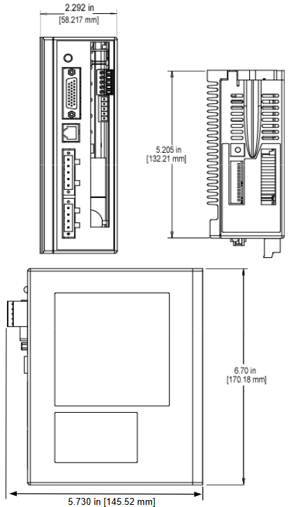
installation dimensions
Basic version (without RS-485): Length 170.18 mm (6.700 in), Width 132.21 mm (5.205 in), Height 52.324 mm (2.060 in).
Equipped with RS-485 version: length 170.18 mm (6.700 in), width 132.21 mm (5.205 in), height 58.217 mm (2.292 in).
(2) Electrical wiring specifications
Wiring safety and sequence
Power off operation, ensure that the drive capacitor is discharged (after power off for ≥ 2 minutes, measure the DC bus voltage<40 V), all power cables and control cables need to be separately shielded, and both ends of the shielding layer should be grounded.
The distance between the power cable (motor/power supply) and the control cable (step/direction/I/O) should be ≥ 20 cm to avoid cross interference; When the cable length exceeds 25 meters, Kollmorgen 3YL-20 choke coil is required (such as SERVOSTAR 601-606 with 4 × 1 mm ² cable).
Core connector definition
J4 (26 pin command I/O): includes step (J4-1/2), direction (J4-3/4), enable (J4-5/6) inputs, fault output (J4-7/8), 9-channel universal input (J4-10~18), universal output (J4-21/22), and 5V power supply (J4-19/25).
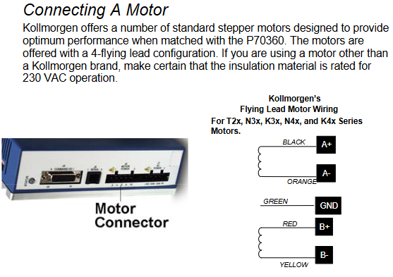
J6 (motor power supply): 4-pole connector, A+/A - (black/orange), B+/B - (red/yellow) connected to the motor winding, PE (green and yellow stripes) connected to the motor casing, pay attention to the motor direction (swapping A ± or B ± can be reversed).
J7 (AC power supply): 4-pin connector, J7-1 is connected to 120/240 VAC live wire, J7-2 is connected to 240 VAC neutral wire, J7-3 is connected to 120 VAC neutral wire, J7-4 is connected to protective earth (PE), and it is forbidden to connect 240 VAC to J7-3.
J2/J3 (RS-485, R4N version only): 5-pin connector, J2-1/RX+, J2-2/RX -, J2-3/TX -, J2-4/TX+, J2-5/GOS (isolated ground), with 120 Ω terminal resistors connected at the beginning and end of the bus.
Typical wiring scheme
Differential step forward/direction: The controller differential output is connected to J4-1 (STEP+)/J4-2 (STEP -), J4-3 (DIR+)/J4-4 (DIR -), and the cable uses shielded twisted pair, with both ends of the shielding layer grounded.
Open collector electrode single ended signal: The controller's open collector electrode output is connected to J4-1 (STEP+)/J4-3 (DIR+), J4-2/J4-4 are grounded, and an external pull-up resistor is required (when the voltage is greater than 5V, a current limiting resistor needs to be connected in series, the formula R CL=(V s − 5) × 100).
Universal input (such as Jog+): When using an internal 5V power supply, connect J4-14 (DIN5) to one end of the button and J4-20 (Pull Up/Dn) to the other end of the button; When using an external 24V power supply, a current limiting resistor should be connected in series (as above).
Parameter configuration and software operation
(1) Switch configuration (hardware quick setting)
Basic parameter settings can be made through the S1 (motor selection) and S2 (function configuration) switches on the top of the driver, and can be started without software:
Motor selection (S1+S2-1): S1 selects the motor series (e.g. S1=1 corresponds to T21... C series, S1=4 corresponds to N31... G series), S2-1 selects the motor type (OFF is the standard series, ON is CTM/CTP series), CTP motors require additional heat dissipation plates (equivalent to 4.125 × 4.125 × 0.25 inch aluminum plates), otherwise the rated current needs to be reduced by 25%.
Step resolution (S2-2~S2-4): Supports 8 levels of resolution, such as ON/ON/ON corresponding to 200 steps/revolution, OFF/OFF/OFF corresponding to 25000 steps/revolution.
Load inertia ratio (S2-5~S2-7): Set according to the load rotor inertia ratio (0-1 to 20-32), used to optimize anti resonance gain, such as OFF/OFF/OFF corresponding to 0-1, ON/ON/ON corresponding to 20-32.
Function switches (S2-8~S2-12): Dynamic smoothing (S2-8/S2-9), current reduction (S2-10), multi-step (S2-11), locked rotor detection (S2-12), ON is enabled, OFF is disabled.
(2) P7000Tools software configuration (advanced settings)
Software installation and connection
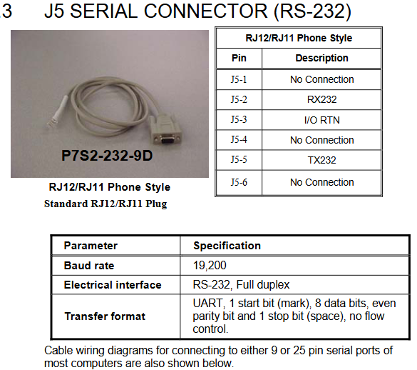
Install P7000Tools (supporting Windows system), connect the PC to the J5 interface of the driver through an RS-232 cable (P7S2-232-9D, RJ12 to 9-pin D-Sub), with a default baud rate of 19200, data bit 8, even parity, and stop bit 1.
After starting the software, scan the drive through "Scan for Connected". For the first connection, configure the node address (1-99) to ensure that there is no conflict with the hardware switch.
Core configuration module
Motor configuration: Select the motor model (or create a custom motor through the "Motor File Editor", enter parameters such as rated current, number of poles, peak torque, etc.), execute the "Probe Stepper Motor" to detect the motor inductance, and optimize the control algorithm.
Mechanical parameters: Set user units (steps/revolutions/millimeters/inches), gear ratio (e.g. 2:1 gearbox set to 2 motor revolutions/load revolutions), and load inertia for motion profile calculation.
Command configuration: Set step resolution (consistent with hardware switch), rotation polarity (reverse motor direction), enable polarity (Active Open/Lost), speed/acceleration/deceleration limits. Jog speed is divided into high and low gears (such as 20 revolutions per second for high speed and 0.5 revolutions per second for low speed).
I/O configuration: Customize 9 universal inputs (such as Jog+/Jog -/EOT+/EOT -/fault reset/start movement), input debounce time (default 1 ms), and universal output functions (such as motor operation/stall/EOT latch).
Advanced settings: Adjust anti resonance frequency (formula)
AResFrequency= 100⋅J Rotor ToothCount⋅T max)、 Dynamic smoothing frequency (formula SmoothingFrequency=9 ⋅ J Rotor ToothCount ⋅ T max), current reduction ratio, and delay.
Sports Profile Generation
Supports 63 independent motion profiles, divided into two modes: AVD (acceleration velocity distance) and T/D (time distance), which can set acceleration and deceleration, target speed, motion distance, delay time, and jump index (chain motion).
Select Profile through "Move Select" input (up to 6 channels, binary encoding). If inputting 1+2 triggers Profile 3, configure "Start Move" input to trigger motion (edge triggered).
Troubleshooting and Safety Standards
(1) Common faults and solutions
Possible causes and solutions for the fault phenomenon
Motor direction error, motor phase wire reversed; Wrong polarity setting for rotation, switching motor A ± or B ± wiring; Change 'Rotation Polarity' through P7000Tools
Drive overheating (red light flashing 4 times), ambient temperature exceeding 40 ° C; poor heat dissipation; Excessive load duty cycle increases fan cooling; Clean the heat sink; Reduce the frequency or load of exercise
Blocked rotor fault (red light flashing once), high motion acceleration/speed; Load inertia exceeding the range reduces Profile acceleration/velocity; Optimize the load inertia ratio setting; Check for mechanical jamming
Overcurrent fault (red light flashing twice), motor winding short circuit; Cable damage; Measure the resistance of the motor winding when the output current exceeds the limit (normally there should be no short circuit); Replace the cable; Reduce motor current (adjusted through software)
Overvoltage fault (red light flashes 3 times) Input voltage is too high; Excessive regenerative energy check AC input voltage (≤ 240 VAC); Increase regenerative resistance; Reduce deceleration rate
Profile cannot execute driver as SDN version (without indexing function); Move Select input configuration error confirmed model as PNN/R4N; Check if the Move Select input is continuous (starting from DIN1); Configure the 'Start Move' input
(2) Safety regulations
Electrical safety
The driver contains high-voltage components (with a maximum DC bus voltage of 440 VDC). After power failure, it is necessary to wait for 2 minutes before touching the wiring terminals. Before operation, measure the bus voltage to be less than 40 V.
The PE wire needs to be reliably grounded (cross-section>10 mm ² or double PE wiring), and the motor casing should be grounded through J6-5 to avoid capacitor coupling causing the casing to become electrified.
It is prohibited to rely on the "Enable" input as an emergency stop. An additional hard wired emergency stop circuit needs to be configured to cut off the power supply to the driver motor (J6).
Mechanical safety
The surface temperature of the motor during operation may exceed 70 ° C, and direct touch is prohibited; Vertical axis applications require additional mechanical braking (the driver brake is only used for parking and frequent braking is prohibited).
Ensure that there are no personnel/obstacles within the range of motion of the motor during debugging. Use low-speed Jog test for the first operation to confirm that there is no jamming or abnormal vibration.
EMC Compliance
An external power filter (such as Corcom 6EQ1) is required, installed at the power inlet, with a filter input/output cable spacing of ≥ 100mm to avoid cross interference.
Shielded twisted pair cables are used for motor and control cables, and the shielding layer is grounded 360 ° (through metal clamps). When the cable length exceeds 15m, a magnetic ring (such as Fair rite 0444167281) needs to be added at the motor end.
- OMRON
- ABB
- General Electric
- EMERSON
- Honeywell
- HIMA
- ALSTOM
- Rolls-Royce
- MOTOROLA
- Rockwell
- Siemens
- Woodward
- YOKOGAWA
- FOXBORO
- KOLLMORGEN
- MOOG
- KB
- YAMAHA
- BENDER
- TEKTRONIX
- Westinghouse
- AMAT
- AB
- XYCOM
- Yaskawa
- B&R
- Schneider
- KONGSBERG
- NI
- WATLOW
- ProSoft
- SEW
- ADVANCED
- Reliance
- TRICONEX
- METSO
- MAN
- Advantest
- STUDER
- DANAHER MOTION
- Bently
- Galil
- EATON
- MOLEX
- DEIF
- B&W
- ZYGO
- Aerotech
- DANFOSS
- Beijer
- Moxa
- Rexroth
- Johnson
- WAGO
- TOSHIBA
- BMCM
- SMC
- HITACHI
- HIRSCHMANN
- Application field
- XP POWER
- CTI
- TRICON
- STOBER
- Thinklogical
- Horner Automation
- Meggitt
- Fanuc
- Baldor
- SHINKAWA
- Other Brands
- UniOP
- KUKA
- Iba
- Beckhoff
-
 Basler D90 96801 100 PCB Card
 -
 Basler XR2002F Voltage Regulator (110 VAC, 48-480 Hz)
 -
 Basler SR8A-2B14B3A Regulator
 -
 Basler 9561500100 Module
 -
 Basler DECS-400 BE1-11 System
 -
 Basler DECS-100-B15 Excitation Control
 -
 Basler SCP 210 Frequency Controller
 -
 Basler SR4A-2B15B3A Static Voltage Regulator
 -
 Basler BE1-32R Power Relay
 -
 Basler PIA2400-17GM Power Interface Adapter
 -
 Basler MVC 232 Manual Voltage Control Module
 -
 Basler SSR 32-12 Static Voltage Regulator
 -
 Basler 5MW AVR Generator Voltage Regulator
 -
 Basler VR63-4B Voltage Regulator
 -
 Basler DECS-100-A05 AVR for Engine Generator
 -
 Basler DECS-100-B15 Automatic Voltage Regulator
 -
 Basler BE1-32R Directional Power Relay
 -
 Basler BE1-87B Differential Relay
 -
 Basler UFOV 260A Protective Module
 -
 Basler 9-2614-02-100 PCB Rev M
 -
Basler DECS-100-B15 Digital AVR
-
 Basler 9284900103 PS DECS-400N
 -
 Basler D4N3H1U Intertie Protection
 -
 Basler DECS-100-B15 A15 AVR
 -
 Basler KR4F Voltage Regulator
 -
 Basler BE26434 T14 Transformer
 -
 Basler SR8A-2B15B3A Regulator
 -
 Westinghouse 774B472A12 AR Relay
 -
Basler DECS-100-B15 AVR
-
Basler XR2002F Regulator 110V
-
Basler SR125-E Static Regulator
-
 Basler SSR 125-12 Regulator
 -
 Basler MOC2599 Motor Pot
 -
 Basler BE1-DFPR Feeder Relay
 -
 Basler CBS 305 Current Boost
 -
 Basler BE1-25 AutoSync
 -
 Basler MVC 300 Voltage Control
 -
 Basler BE3-25A AutoSync
 -
 Basler KR7FF Static Regulator
 -
 Basler 90-49000-100 Regulator
 -
 Basler 880 kVA Dry Type Transformer Specs
 -
 Basler Electric BE1-25 Sync-Check Relay Specs
 -
 Basler SSR 125-12 Voltage Regulator Specs
 -
 Basler Electric BE1-851 Overcurrent Relay Review
 -
Basler Electric 149D930G02 Control Sub-Assembly
-
 Basler Electric BE1-81O/UT Frequency Relay Specs
 -
 Basler Electric BE1-51/27C Overcurrent Relay
 -
 Basler Electric 149D956G02 Industrial Component
 -
Basler Electric BE1-51A Overcurrent Relay Specs
-
 Basler Electric BE1-40Q Loss of Excitation Relay
 -
 Basler DECS-200 Excitation Control System
 -
 Basler DECS-200 Voltage Regulator 56-277V AC / 125V DC
 -
Basler BE1-87T Transformer Differential Relay
-
 Basler RDP-110-S1 Protection Relay
 -
 Basler BE1-700V Digital Protective Relay
 -
 Basler BE1-951 Overcurrent Protection System
 -
 Basler DECS-300 Digital Excitation Control
 -
 Basler DECS-200 Digital Excitation Control
 -
 Basler DECS-200-1C Excitation Control System
 -
Basler DECS-200-1L Digital Excitation Control
-
 Basler Electric BE1-GPS Generator Protection System
 -
Basler Electric DECS-200-1C Digital Excitation Controller
-
 Basler Electric DECS125-15 Excitation Control with Power Module
 -
 Basler Electric BE1-87G Differential Relay
 -
 Basler Electric BE1-11 Protection System I5A3M2P2N0EA00
 -
Basler Electric DECS-200-1C Excitation Control System
-
Basler Electric BE1-11g Generator Protection Relay
-
Basler Electric DECS 125-15-B2C1 V2.0.9 Excitation Control
-
 Basler Electric BE1-81O/UT3ED1JA7N2F Frequency Relay
 -
Basler Electric BE1-81O/UT3EE1YB7N1F Frequency Relay
-
 Basler Electric DECS-200-1L Digital Excitation Control System
 -
Basler DECS125-15-B2C1 Excitation Control
-
 Basler 9507900205 SSR Retrofit Voltage Regulator
 -
 Basler BE2000E Digital Voltage Regulator
 -
 Basler BE1-GPS Generator Protection System
 -
Basler DECS-250-CN1CN1N Digital Excitation Control
-
 Basler DGC-2020 Genset Controller
 -
 Basler BE1-81O UT3ED1LA7N0F Frequency Relay (Variant)
 -
 Basler BE1-81O UT3EE1YA9S0F Frequency Relay (Variant)
 -
Basler BE1-81O Over/Under Frequency Relay
-
Basler DECS125-15 Digital Excitation Control
-
Basler Electric BE1-951 Overcurrent Protection System
-
 Basler Electric BE1-700V Digital Protective Relay
 -
 Basler Electric APR63-5 Automatic Voltage Regulator
 -
Basler Electric BE1-851 Overcurrent Protection System
-
Basler Electric DECS-250-LN1SN1N Excitation Control
-
 Basler Electric BE1-87T Transformer Differential Relay
 -
Basler Electric DECS-200-1L Excitation Control System
-
 Basler Electric 9310300100 DECS-300 Excitation Control
 -
 Basler Electric SSE-N 125-4.5KW Shunt Exciter Regulator
 -
 Basler Electric DGC-2020HD-5NS1DNSBA Genset Controller
 -
Basler Electric BE1-81-O/UT3EE1JB7N1F Frequency Relay
-
Basler Electric BE1-81T1EE1WA0N1F Frequency Relay
-
 Basler Electric BE1-25M1EA6PN5R1F Sync-Check Relay
 -
 Basler Electric BE1-GPS Generator Protection System
 -
Basler Electric DECS-250-LN1SN1N Excitation Control Rev V
-
 Basler Electric DECS-250-CN2CN1N Excitation Control
 -
Basler Electric BE1-50/51B-207 Overcurrent Relay
-
Basler Electric DECS-300-C0N0 Excitation Control System
-
Basler Electric DECS-200 Digital Excitation Control System
-
Basler Electric DECS-250-LN1CN1N Excitation Unit
-
Basler Electric DECS-250 LN2SA1D Excitation Unit Specs
-
Basler Electric BE1-87T Transformer Relay Review
-
Basler Electric BE1-11 Protection System
-
Basler Electric BE1-GPS100-E4N1H1N Protection System
-
 Allen-Bradley 442G-MABH-R Safety Module
 -
 Beckhoff CX1030-0111 PLC Assembly Profile
 -
 FANUC IC693CPU364 PLC Module
 -
 Orange Denmark Type 200816 220 PLC Specs
 -
 OMRON C200H-SNT31 Sysmac PLC Module
 -
 Allen Bradley 20AB022A3AYNANC0 PowerFlex 70
 -
 OMRON C200HW-PCU01 Position Control Unit
 -
 ABB AO845A-eA Analog Output Module
 -
 OMRON CJ1M-CPU22 CPU Unit
 -
 Allen Bradley 100-E265ED11 Contactor
 -
 Honeywell 51304511-100 Interface Module
 -
 SOLEXY BXF3S0101N0018 Gateway Module
 -
 OMRON CJ2H-CPU65 CPU Unit
 -
 Automation Direct GS2-45P0 AC Drive
 -
 M68-2000 2-Axis Motion CNC Controller
 -
 OMRON CJ1M-CPU11 V3.0 PLC CPU Unit
 -
 OMRON CJ1W-NC413 4-Axis Positioning Controller
 -
 OMRON 3G2A3-PRO16 Programming Console HMI
 -
 Siemens 3VT8440-2AA04-2GA2 Molded Case Circuit Breaker
 -
 Siemens 3RT5045 Contactor Series
 -
 OMRON C200HS-CPU01-E SYSMAC PLC Controller
 -
 OMRON C500-NC103-E Positioning Control Unit
 -
 OMRON CJ1W-TC001 Temperature Control Unit


