
Watlow PM LEGACY ™ Limit controller
Model specifications: available in two panel sizes: 1/32 DIN (PM3) and 1/16 DIN (PM6), supporting AC/DC dual power supply mode and compatible with multiple input/output configurations.
Core advantages: simple and easy to operate menu, PID self-tuning function, multi bus communication support, FM certified over/under temperature protection, three-year warranty, and features such as touch safe packaging, waterproof and dustproof (NEMA 4X/IP66/IP67).
Watlow PM LEGACY ™ Limit controller
Product Core Information
Product positioning: Industrial grade PID controller, suitable for basic temperature control and limit monitoring scenarios, supporting composite functions such as PID control, limit detection, and multi class alarms.
Model specifications: available in two panel sizes: 1/32 DIN (PM3) and 1/16 DIN (PM6), supporting AC/DC dual power supply mode and compatible with multiple input/output configurations.
Core advantages: simple and easy to operate menu, PID self-tuning function, multi bus communication support, FM certified over/under temperature protection, three-year warranty, and features such as touch safe packaging, waterproof and dustproof (NEMA 4X/IP66/IP67).
Product Features and Technical Parameters
(1) Input function
Analog input
Type and Range: Supports thermocouples (such as J, K, T, E, etc., with different measurement ranges for different types, such as J type -346 to 2192 ° F, i.e. -210 to 1200 ° C), RTDs (calibrated at 100 Ω, 1k Ω, 0 ° C, in accordance with DIN curves, 2-3 wire system, 20 Ω total lead resistance, typical excitation current 0.09mA, lead resistance per ohm may cause 0.03 ° C reading deviation), thermistors (5k Ω, 10k Ω, 20k Ω, 40k Ω), process signals (voltage 0-10VDC, input impedance 20k Ω; current 0-20mA, input impedance 100 Ω); Millivolt 0-50mVdc, input impedance 20k Ω), 1k Ω potentiometer, and all analog inputs can be scaled to meet different measurement requirements.
Configuration requirements: Sensor type (sEn), linearization (Lin, for thermocouples), number of leads (rt.L, for RTDs), unit, scaling high and low values (s.Lo, s.hi), range high and low values (r.Lo, r.hi) and other parameters need to be configured in the "Setup Page - Analog Input Menu" to ensure compatibility with the connected input device. For example, thermocouples should pay attention to polarity (negative pole is usually red, connected to S1 terminal), and the extension wire should be made of the same material as the thermocouple to reduce errors; The S1 lead (usually white) of a 3-wire RTD needs to be connected to R1 and/or R2 terminals, and the resistance of the three leads must be consistent to ensure accuracy.
Performance indicators: thermocouple input impedance>20M Ω, maximum source resistance 2k Ω, with 3 µ A open circuit sensor detection function; The input accuracy of RTD is affected by lead resistance and needs to be compensated through calibration; The scaling range of process input can be set according to actual needs, such as 4-20mA corresponding to 0-100% humidity, etc.
Digital input
Hardware configuration: The model with Digital Input/Output (DIO) hardware includes two sets of terminals (5 and 6), each set can be configured as an input or output, and needs to be set through the "Direction" parameter in the "Setup Page Digital Input/Output Menu" (input can choose voltage input or dry contact input).
Input characteristics: When voltage is input, the maximum input voltage is 36Vdc, the activation voltage is>3Vdc (0.25mA), and the non activation voltage is<2VDC; When using dry contact input, the activation resistance is less than 100 Ω, the non activation resistance is greater than 500 Ω, and the maximum short-circuit current is 13mA. The update rate is 10Hz, which can be used to detect equipment start stop status, external trigger signals, etc.
Special Input: The Reset button on the front of the controller can be configured as a digital input through the "Digital Input Function" parameter in the "Setup Page Reset Key Menu" to achieve function switching, such as limit reset, alarm mute, etc.
(2) Output function
Output type and characteristics
Mechanical relay: Form C type (output 1, 3), rated load 5A@240Vac Or 30Vdc (resistive), minimum load 20mA@24V , 125VA pilot duty at 120/240Vac, 25VA pilot duty at 24Vac, with a lifespan of 100000 cycles (rated load), supporting AC/DC loads, no power output, requiring external power supply; Form A type (outputs 2 and 4) has parameters similar to Form C type, with only normally open contacts. Output 2 is default bound to the limit function and serves as the main output for limit protection.
Solid state relay (SSR): Form A type (output 3, 4), rated load 0.5A@20-264Vac (Resistive), 20VA pilot duty at 120/240VAC, optocoupler isolation, contactless suppression, maximum off state leakage current of 105 µ A, minimum holding current of 10mA, only supports AC load, no power output.
Switching DC/collector open circuit output: Supports outputs 1, 3, and 4, with a maximum open circuit voltage of 22-25Vdc, a maximum current of 30mA for a single output, and a maximum total current of 40mA for paired outputs (1&2, 3&4). Typical driver 4.5Vdc@30mA Short circuit current limit<50mA (NPN transistor current), can drive external solid-state relays, supports multiple sets of DIN-A-MITE relays in parallel/series (such as 1 pole up to 4 sets in parallel/series, 2 poles up to 2 sets in parallel/series, 3 poles up to 2 sets in series).
Universal process output: Only supports 3 outputs, can be configured as voltage (0-10VDC, minimum load 1k Ω) or current (0-20mA, maximum load 800 Ω) output, with scaling function (s.Lo, s.hi, r.Lo, r.hi), can be used to retransmit process values or set values, output accuracy ± 15mV (voltage), ± 30 µ A (current), temperature stability 100ppm/° C, need to configure parameters such as type (o.ty), function (fn), and retransmission source (r.Sr) in the "Setup Page Output Menu".
Output configuration logic: All outputs need to be assigned functions (such as limit, alarm, retransmission, etc.) and function instances (such as alarm 1-4, limit 1, etc.) in the corresponding menu (Output Menu or Digital Input/Output Menu) of the "Setup Page". For example, output 1 can be configured as "Alarm 1" and output 2 can be fixed as "Limit"; Support multiple outputs associated with the same functional instance, such as alarm 2, which can simultaneously trigger output 1 (indicator light) and output 5 (buzzer).
(3) Core control and protection functions
PID control: supports hot/cold control, switch control, P, PI, PD, PID control algorithms (not specific to limit controllers), with automatic tuning function, can be started through "Operations Page" or configuration software, sampling rate input 10Hz, output 10Hz, control accuracy is affected by input sensor accuracy, calibration status and load characteristics, calibration accuracy is ± 0.1% range ± 1 ° C (0.2% for S-type thermocouples, 0.2% for T-type thermocouples below -50 ° C) at rated ambient temperature (25 ° C ± 3 ° C) and rated line voltage, minimum range 1000 ° F (540 ° C), maximum temperature stability ± 0.1 ° F/° F (± 0.1 ° C/° C) Environmental temperature rise.
Limit protection: As the core function, it supports high/low limit or dual limit monitoring. The limit upper and lower limits (Lh. s, LL. s), hysteresis value (L.hy, 0.001-9999 ° F/° C, default 3 ° F or 2 ° C), and limit sides (L.sd, high, low, or dual sides) can be set in the "Setup Page Limit Menu"; When the process value exceeds the limit range, output 2 (Form A relay) loses power, cuts off the load power supply, and maintains a locked state, requiring manual reset (through the Reset button, digital input, or communication command); Support limit reset source configuration (sfn. a, such as digital input, function keys) to ensure that normal operation can only be restored after troubleshooting.
Alarm function: Supports 4 sets of alarms (1-4), which can be configured as process alarms (high/low alarms, deviation alarms, etc.). Set the alarm type (a.ty), source (sr.a, such as analog input 1-2), upper and lower limits (a.hi, a.Lo), hysteresis value (a.hy), logic (a.Lg, power on alarm or power off alarm), latch (a.La, whether to manually clear), blocking (a.bL, whether to block alarm when starting or setting value changes), mute (a.si, whether to support mute), delay time (a.dL, 0-9999 seconds) and other parameters in the "Setup Page Arm Menu"; When an alarm is triggered, it can be notified through output actions (such as indicator lights, buzzers) or communication signals. Locked alarms need to be cleared through the "Clear Alarm (a.CLr)" command, and silent alarms need to pause output through the "Silence Alarm (a.sir)" command.
(4) Communication function
Support protocols and ports
Modbus RTU: Supports EIA-485 (Port 1/2) and EIA-232 (Port 2), with Port 1 supporting Standard Bus by default and switchable to Modbus RTU; Modbus addresses 1-247 (Standard Bus addresses 1-16), baud rates of 9600, 19200, 38400bps, parity bits none/odd/even, data bits 8, stop bit 1; Supports 16 bit register read and write, floating-point parameters occupy 2 registers, default low byte first (can set "Modbus Word Order" to Lohi or hiLo in the "Setup Page Communications Menu"); Supports Map 1 (compatible with old models) and Map 2 (compatible with new features), and recommends using Map 2 for new applications.
EtherNet/IP ™ Compared to Modbus TCP: only supported on port 2, requires configuration of IP address (fixed or DHCP), subnet mask, gateway, supports 10/100Mbps Ethernet, and can run both protocols simultaneously; CIP implicit assembly (input/output member count 1-20), explicit communication supports Class/Instance/Attribute addressing, compliant with ODVA standards.
DeviceNet ™: Port 2 support, node addresses 0-63, baud rates 125, 250, 500kbps, supports Quick Connect, CIP implicit assembly input/output members up to 200, explicit communication for configuration and diagnosis.
Profibus DP: Port 2 support, addresses 0-126, maximum baud rate of 12Mbps, supports DP-V0 (cyclic data exchange) and DP-V1 (non cyclic data exchange, used for configuration and diagnosis); GSD file configuration is required, supporting up to 32 devices per network segment, with a maximum transmission distance of 1200 meters (EIA-485), and a terminal resistance configuration option (150 Ω).
Communication configuration and tools: All communication parameters need to be configured in the "Setup Page Communications Menu" (such as protocol, address, baud rate, IP parameters, etc.); Can be accessed through Watlow PM LEGACY ™ The Limit Configurator software (free download from the official website) enables communication between the PC and the controller, supporting online configuration, parameter backup/recovery, device scanning, and other functions; During the communication process, attention should be paid to cable selection (such as using twisted pair for EIA-485, avoiding parallel wiring with power lines), terminal resistance (only network end devices need to be connected to a 120 Ω resistor), and grounding isolation (to prevent grounding loops).

Installation and wiring
(1) Installation process
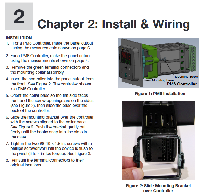
Panel perforation: The PM3 controller needs to be perforated according to the size on page 6 of the document, and the PM6 controller needs to be perforated according to the size on page 7 to ensure that the controller can be smoothly embedded into the panel.
Component disassembly: Remove the green terminal connector and installation ring assembly to avoid damaging the components during installation.
Controller embedding: Insert the controller into the opening from the front of the panel. Taking PM6 as an example, ensure that the installation direction is correct.
Installation ring fixation: Move the installation ring base plane forward, with the screw opening facing the side, and slide it over the back of the controller; Slide the installation bracket over the controller again, aligning the screws with the base, and gently push until the hook clicks into the slot of the housing; Finally, use a Phillips screwdriver to tighten the two # 6-19 x 1.5 inch screws with a torque of 3-4 inch pounds, ensuring that the device is flush with the panel.
Terminal reset: Reinstall the terminal connector to its original position to complete the installation.
Installation spacing requirements: 1/32 DIN (PM3) recommends a panel spacing of 44.96-45.47mm (1.77-1.79 inches), a minimum panel thickness of 21.6mm (0.85 inches), and a panel thickness range of 1.53-9.52mm (0.060-0.375 inches); 1/16 DIN (PM6) recommends a panel spacing of 44.96-45.47mm (1.77-1.79 inches), with other thickness requirements consistent with PM3 to ensure heat dissipation and operational space.
(2) Wiring specifications
Power wiring
Low power model (PM6 [L, M] [3,4} _J-A_G _): supports 12-40Vdc, 20-28Vac (50/60Hz), maximum power consumption of 10VA (PM6), power terminals are 98 (ac/dc+) and 99 (ac/dc -) of Slot C, pay attention to voltage polarity, and comply with NEC or local electrical standards to avoid overvoltage or reverse connection damage to equipment.
High power model (PM6 [L, M] [1,2} _J-A_G _): Supports 85-264Vac, 100-240Vac (Semi Sig F47 standard, 50/60Hz), maximum power consumption of 10VA (PM6), power terminals are also 98 and 99 of Slot C, and suitable fuses are required to prevent overload.
Input wiring
Analog input (Slot A): The terminals of universal sensor input 1 include T1, S1, R1 (thermocouple+ RTD S1、 Potentiometer sliding end, S3 (thermocouple - RTD S3、 Current - etc.), wiring needs to be done according to the sensor type, for example, thermocouples need to distinguish between positive and negative poles, and RTD 3-wire system needs to connect S1 to R1/R2; The process input (voltage/current/millivolts) should be wired according to the terminal identification (such as voltage+connected to S1, voltage - connected to S3) to ensure signal integrity.
Digital input (Slot C): The terminals of digital input 5/6 are D5, D6 (signal), and B5 (common terminal). The voltage input needs to be connected to a DC power supply (such as 24Vdc), and the dry contact input needs to be directly connected to an external contact. When wiring, attention should be paid to isolating from other circuits to prevent interference.
Output wiring
Mechanical relay/SSR (Slot A/B): The terminals of Form C relay are L_ (normally open), K0 (common), and J2 (normally closed), while the terminals of Form A relay are L_ (normally open) and K0 (common). The wiring should be based on the load type (AC/DC), and the load current should not exceed the rated value; SSR only supports AC loads, please pay attention to the phase and voltage range.
Switch DC/collector open circuit (Slot A/B): The terminals are W_ (dc+), X_ (dc -, collector open circuit), and Y1 (common), and an external power supply is required to drive the load (such as a solid-state relay) to ensure that the power supply voltage matches the load and avoid short circuits.
Universal process output (Slot B): The voltage output terminals are F3 (-) and G3 (+), and the current output terminals are F3 (-) and H3 (+). The wiring should be based on the configured output type, and the load impedance should meet the requirements (minimum voltage output of 1k Ω, maximum current output of 800 Ω).
Communication wiring
EIA-485 (Slot C/B): The terminals of Standard Bus/Modbus RTU are CC (common) CA(T-/R-)、CB(T+/R+), Twisted pair cables (such as Cat 5) should be used, with a Daisy chain network topology, a maximum of 16 nodes (Standard Bus) or 247 nodes (Modbus), a maximum transmission distance of 1200 meters, and a 120 Ω terminal resistor connected to the end device.
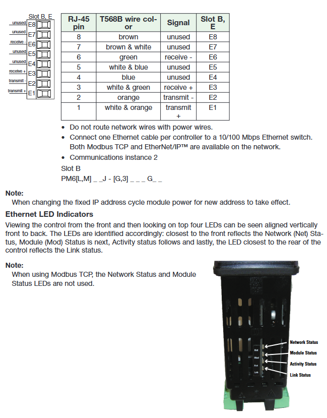
EtherNet/IP ™/ Modbus TCP (Slot B): The RJ-45 interface is wired according to the T568B standard, with pins E1 (white orange, transmit+), E2 (orange, transmit -), E3 (white green, receive+), E6 (green, receive -). The other pins are not used and need to be connected to a 10/100Mbps Ethernet switch.
DeviceNet ™ (Slot B): The terminals are V+(power+), CH (CAN_S), SH (shielded), CL (CAN_L), V - (power -), and shielded twisted pair cables are required. The node address is 0-63, the baud rate is 125/250/500kbps, and the shielding layer needs to be single ended grounded.
Profibus DP (Slot B): The terminals are VP (+5Vdc), B (T+/R+), A (T -/R -), DG (digital ground), trB (terminal resistance B), trA (terminal resistance A), and require Profibus dedicated cables. The end device needs to be equipped with a terminal resistance (150 Ω), address 0-126, and a maximum transmission distance of 1200 meters.
Wiring precautions: All wiring must comply with NEC or local safety standards, and power-off operation is required; The wire specification is 0.0507-3.30mm ² (30-12 AWG) single stranded wire, or two 1.31mm ² (16 AWG) wires, with a terminal torque of 0.56 Nm (5.0 inch pounds); Unused terminals must not be wired to prevent short circuits; Analog inputs, digital I/O, switch DC outputs, and process outputs must be electrically isolated to prevent grounding loops; When switching inductive loads (such as relay coils and solenoid valves), it is necessary to install an RC suppressor (Watlow recommended model 0804-0147-0000) to avoid electromagnetic interference damaging the equipment.
Operation and Configuration Guide
(1) Page navigation and basic operations
page switching
Home Page: By default, it displays process values (PV) and limit states (safE/faiL), which can be returned from any page by long pressing the Reset button for 2 seconds.
Operations Page: Press and hold the Up+Down key for 3 seconds from the home page to enter, displaying parameters that can be monitored/modified such as analog input values, limit status, digital I/O status, alarm status, etc. Use the Up/Down key to switch menus, the Advance key to enter submenus, and the Reset key to return to the previous level or home page.
Setup Page: Press and hold the Up+Down key for 6 seconds from the homepage to enter (hold down continuously until "SEt" is displayed), used to configure input, output, alarm, communication, global parameters, etc. The operation logic is consistent with the operation page, and some parameters need to be restarted to take effect after modification.
Factory Page: Press and hold the Advance+Reset button for 6 seconds from the homepage to enter. It is used for customizing the homepage, calibration, security settings (password/lock), diagnosis, etc. Caution is required when operating, and some functions (such as calibration) require professional personnel to perform.
Button Function
Up/Down keys: Modify writable parameter values (such as limit settings) on the homepage, and switch parameters/options in the menu.
Advance button: Switch display parameters on the homepage (such as low limit → high limit), enter submenus in the menu or confirm the selection.
Reset button: Reset limit (after troubleshooting), clear alarm (latch alarm), return to the previous page, long press for 2 seconds to return to the home page.
Function key (Fn, only 1/16 DIN): a programmable key that can configure functions (such as limit reset, alarm mute, user settings recovery, etc.) in the "Setup Page Function Key Menu", supporting level triggering or edge triggering.
(2) Key parameter configuration
Home page customization: Enter the "Factory Page Custod Menu (CuSt)" and select 20 parameters to add to the homepage (such as analog input values, limit settings, alarm status, etc.). Parameter instances (such as alarms 1-4) need to be selected separately; Set the number of display pairs (1-10) through "Setup Page Global Menu-d-prs (Display Pairs)", and set the automatic switching time (0-60 seconds, 0 is not automatic switching) through "d.ti (Display Time)". Custom homepage parameters will be updated synchronously after modification on the original page (operation page/settings page), and vice versa.
Simulated input configuration (Setup Page Analog Input Menu)
Sensor type (sEn): Select the type that matches the connected device (such as thermocouple J-type, RTD 100 Ω, 0-20mA, etc.), "off" indicates disabling the input.
Linearization (Lin): Only thermocouples need to be set, select the corresponding linearization curve for the thermocouple type (such as J, K, T, etc.).
Scaling and Range (s.Lo/s.hi, r.Lo/r.hi): Process inputs need to be set, for example, 4-20mA corresponds to 0-100 ℃, so s.Lo=4.00mA, s.hi=20.00mA, r.Lo=0.0 ℃, r.hi=100.0 ℃; The scaling value is the input signal range, and the range value is the display/control range. It supports reverse scaling (e.g. 50psi corresponds to 4mA, 10psi corresponds to 20mA).
Filtering (fiL): Set the filtering time constant (0.0-60.0 seconds, default 0.5 seconds) to smooth the input signal, reduce noise interference, and filter without affecting the limit sensor signal.
Calibration offset (i.Ca): Used to compensate for sensor errors or lead resistance, it can be modified in the "Operations Page Analog Input Menu" (-1999.000-9999.000 ° F/° C), with positive offset increasing the input value and negative offset decreasing the input value.
Set Page Limit Menu
Limit Sides (L.sd): Select "high", "Lo І", or "both" to determine the upper, lower, or both limits of the monitoring process value.
Limit setting value (Lh. s/LL. s): Set the high/low limit trigger value (-1999.000-9999.000 ° F/° C, default 0.0 ° F or -18.0 ° C), which needs to be set according to process requirements, for example, the high limit of the heating equipment is set to 200 ℃ and the low limit is set to 50 ℃.
Lag value (L.hy): Set the process value deviation required for limit reset (0.001-9999.000 ° F/° C, default 3.0 ° F or 2.0 ° C), for example, if the high limit is 200 ℃ and the lag is 2 ℃, the process value needs to drop below 198 ℃ to reset the limit.
Reset source (sfn. a/si. a): Select the trigger source for limit reset (such as numeric input 5, Function key) and corresponding instance to ensure that the reset operation is effective.
Alarm configuration (Setup Page Arm Menu)
Alarm type (a.ty): Select "off" or "Pr.AL", process alarms support high/low alarms (set according to a.sd).
Alarm source (sr.a/is.a): Select the input source (such as analog input 1) and instance for alarm monitoring to ensure matching with the controlled object.
Alarm setting value (a.hi/a.Lo): Set the high/low alarm trigger value (-1999.000-9999.000 ° F/° C, default high alarm 300.0 ° F or 150.0 ° C, low alarm 32.0 ° F or 0.0 ° C), which needs to be set according to the process safety range.
Lock and mute (a.La/a.si): When "a.La" is set to "LAt (lock)", it needs to be manually cleared after the alarm is triggered; When "a.si" is set to "on", the alarm output can be muted through the Reset key or communication command.
Communication Configuration (Setup Page Communications Menu)
Protocol (pCoL): Select the protocol for port 1 (Standard Bus or Modbus RTU), and port 2 supports Modbus RTU, EtherNet/IP, DeviceNet, Profibus DP depending on the model.
Address and baud rate: Modbus addresses 1-247, Standard Bus addresses 1-16, DeviceNet addresses 0-63, Profibus addresses 0-126; The baud rate should be selected according to network requirements (such as Modbus RTU 9600bps, DeviceNet 250kbps), and all network devices should be consistent.
IP parameters (EtherNet/IP/Modbus TCP only): Set "iP. ∧Џ" to "dhCP (auto fetch)" or "F.Add (fixed IP)". Fixed IP requires setting ip.f1-ip.f4 (IP address), ips1-ips4 (subnet mask), and ipg1-ipg4 (gateway). After modification, the controller needs to be restarted to take effect.
(3) Calibration operation
Calibration prerequisite: It is necessary to confirm that the input/output readings exceed the accuracy range (such as a large deviation between the simulated input display value and the standard signal source). Before calibration, a standard signal source with higher accuracy than the equipment (such as a high-precision thermocouple simulator, DC power supply), a high-precision measuring instrument (such as a 4.5 bit multimeter), and the controller must be at a stable ambient temperature (25 ° C ± 3 ° C).
Analog Input Calibration (Factory Page Calibration Menu)
Input offset (ELi. o): Connect a low range standard signal (such as a thermocouple 0.000mV, current 0.000mA), read the controller display value, and if there is a deviation from the standard value, adjust "ELi. o" to make the display value equal to the standard value (range -1999.000-9999.000).
Input slope (ELi. S): Connect a high range standard signal (such as thermocouple 50.000mV, current 20.000mA), read the controller display value, and if there is a deviation from the standard value, adjust "ELi. S" to make the display value equal to the standard value (range -1999.000-9999.000). Slope calibration affects the accuracy of the entire range.
Output Calibration (Factory Page Calibration Menu)
Output offset (ELo. o): Configure the output to a low range value (such as voltage 0.0V, current 4.0mA), measure the actual output value with a multimeter, adjust "ELo. o" to make the actual value equal to the set value (range -1999.000-9999.000).
Output slope (ELo. S): Configure the output to a high range value (such as voltage 10.0V, current 20.0mA), measure the actual output value with a multimeter, adjust "ELo. S" to make the actual value equal to the set value (range -1999.000-9999.000).
Calibration precautions: Calibration parameters need to be saved to EEPROM (via "Setup Page Global Menu Usr. s") to avoid power loss; After calibration, it is necessary to verify the accuracy of multiple intermediate points to ensure that the entire range meets the requirements; Non professionals are not recommended to perform calibration operations, please contact Watlow technical support.
- OMRON
- ABB
- General Electric
- EMERSON
- Honeywell
- HIMA
- ALSTOM
- Rolls-Royce
- MOTOROLA
- Rockwell
- Siemens
- Woodward
- YOKOGAWA
- FOXBORO
- KOLLMORGEN
- MOOG
- KB
- YAMAHA
- BENDER
- TEKTRONIX
- Westinghouse
- AMAT
- AB
- XYCOM
- Yaskawa
- B&R
- Schneider
- KONGSBERG
- NI
- WATLOW
- ProSoft
- SEW
- ADVANCED
- Reliance
- TRICONEX
- METSO
- MAN
- Advantest
- STUDER
- DANAHER MOTION
- Bently
- Galil
- EATON
- MOLEX
- DEIF
- B&W
- ZYGO
- Aerotech
- DANFOSS
- Beijer
- Moxa
- Rexroth
- Johnson
- WAGO
- TOSHIBA
- BMCM
- SMC
- HITACHI
- HIRSCHMANN
- Application field
- XP POWER
- CTI
- TRICON
- STOBER
- Thinklogical
- Horner Automation
- Meggitt
- Fanuc
- Baldor
- SHINKAWA
- Other Brands
- UniOP
- KUKA
- Iba
- Beckhoff
-
 Basler Electric DECS-200-1L Digital Excitation Control System
 -
 Basler DECS125-15-B2C1 Excitation Control
 -
 Basler 9507900205 SSR Retrofit Voltage Regulator
 -
 Basler BE2000E Digital Voltage Regulator
 -
 Basler BE1-GPS Generator Protection System
 -
 Basler DECS-250-CN1CN1N Digital Excitation Control
 -
 Basler DGC-2020 Genset Controller
 -
 Basler BE1-81O UT3ED1LA7N0F Frequency Relay (Variant)
 -
 Basler BE1-81O UT3EE1YA9S0F Frequency Relay (Variant)
 -
 Basler BE1-81O Over/Under Frequency Relay
 -
 Basler DECS125-15 Digital Excitation Control
 -
 Basler Electric BE1-951 Overcurrent Protection System
 -
 Basler Electric BE1-700V Digital Protective Relay
 -
 Basler Electric APR63-5 Automatic Voltage Regulator
 -
 Basler Electric BE1-851 Overcurrent Protection System
 -
 Basler Electric DECS-250-LN1SN1N Excitation Control
 -
 Basler Electric BE1-87T Transformer Differential Relay
 -
 Basler Electric DECS-200-1L Excitation Control System
 -
 Basler Electric 9310300100 DECS-300 Excitation Control
 -
 Basler Electric SSE-N 125-4.5KW Shunt Exciter Regulator
 -
 Basler Electric DGC-2020HD-5NS1DNSBA Genset Controller
 -
Basler Electric BE1-81-O/UT3EE1JB7N1F Frequency Relay
-
 Basler Electric BE1-81T1EE1WA0N1F Frequency Relay
 -
 Basler Electric BE1-25M1EA6PN5R1F Sync-Check Relay
 -
 Basler Electric BE1-GPS Generator Protection System
 -
Basler Electric DECS-250-LN1SN1N Excitation Control Rev V
-
 Basler Electric DECS-250-CN2CN1N Excitation Control
 -
 Basler Electric BE1-50/51B-207 Overcurrent Relay
 -
Basler Electric DECS-300-C0N0 Excitation Control System
-
Basler Electric DECS-200 Digital Excitation Control System
-
Basler Electric DECS-250-LN1CN1N Excitation Unit
-
Basler Electric DECS-250 LN2SA1D Excitation Unit Specs
-
Basler Electric BE1-87T Transformer Relay Review
-
Basler Electric BE1-11 Protection System
-
Basler Electric BE1-GPS100-E4N1H1N Protection System
-
 Allen-Bradley 442G-MABH-R Safety Module
 -
 Beckhoff CX1030-0111 PLC Assembly Profile
 -
 FANUC IC693CPU364 PLC Module
 -
 Orange Denmark Type 200816 220 PLC Specs
 -
 OMRON C200H-SNT31 Sysmac PLC Module
 -
 Allen Bradley 20AB022A3AYNANC0 PowerFlex 70
 -
 OMRON C200HW-PCU01 Position Control Unit
 -
 ABB AO845A-eA Analog Output Module
 -
 OMRON CJ1M-CPU22 CPU Unit
 -
 Allen Bradley 100-E265ED11 Contactor
 -
 Honeywell 51304511-100 Interface Module
 -
 SOLEXY BXF3S0101N0018 Gateway Module
 -
 OMRON CJ2H-CPU65 CPU Unit
 -
 Automation Direct GS2-45P0 AC Drive
 -
 M68-2000 2-Axis Motion CNC Controller
 -
 OMRON CJ1M-CPU11 V3.0 PLC CPU Unit
 -
 OMRON CJ1W-NC413 4-Axis Positioning Controller
 -
 OMRON 3G2A3-PRO16 Programming Console HMI
 -
 Siemens 3VT8440-2AA04-2GA2 Molded Case Circuit Breaker
 -
 Siemens 3RT5045 Contactor Series
 -
 OMRON C200HS-CPU01-E SYSMAC PLC Controller
 -
 OMRON C500-NC103-E Positioning Control Unit
 -
 OMRON CJ1W-TC001 Temperature Control Unit
 -
 OMRON NJ301-1100 NJ-PA3001 PLC System EtherCAT
 -
 Pilz 773100 M1P Safety Relay Base Unit
 -
 Siemens SINUMERIK 840D SL NCU 720.3B with PLC 317-3 PN/DP
 -
 Siemens 6AV6618-7GD01-3AB0 HMI Panel
 -
 OMRON F150-C15E-3 Vision Mate Controller PLC Overview
 -
 Mitsubishi MELSEC A Series PLC System A63P A3ACPU A616AD A68RD3
 -
 M68-2000 2 Axis Motion Controller SCE SERVO CNC
 -
 OMRON FZ-S2M PLC Camera Vision System
 -
 VISOLUX SLVA-4K PLC Module from Elektronik GmbH
 -
 OMRON CJ1M-CPU23 V2.0 PLC CPU Unit
 -
 ABB AI86-16CHF PCB Card 5761751-9 B Specifications
 -
 Allen-Bradley 100-D140ZJ22L Contactor Overview
 -
 Merlin Gerin PB80 PLC Rack
 -
 WEIR WE203 Power Supply PLC
 -
 OMRON NX-TS3102 Temperature Input Unit
 -
 Siemens 6ES7146-6FF00-0AB0 I/O Module
 -
 Fanuc A16B-3300-0057 Circuit Board
 -
 OMRON CJ1W-IDP01 Input Module
 -
 Siemens 6FX2007-1AD13 Handheld Unit
 -
 Gems EM54 PLC Module PCB
 -
 Beckhoff CX2030-0121 Embedded PC CPU
 -
 OMRON NJ301-1100 Machine Automation Controller
 -
 Biesse Rover CNI PLC 2153 030 7146.30 Numerical Control Module
 -
 OMRON CJ1W DA08V Analog Output Module
 -
 OMRON CS1D ETN21D Ethernet Module
 -
 Allen Bradley 1768 L43 CompactLogix Controller
 -
 Schneider TWDLMDA40DTK Twido PLC Module
 -
 Mitsubishi NZ2EX2B 60AD4 Analog Input Module
 -
 OMRON NS8 TV00B V2 Touch Display Panel
 -
 Mitsubishi AY71 CMOS TTL Output Module
 -
 OMRON C500 CPU11 E Processor Module
 -
 OMRON CJ1W PTS51 Temperature Input Module
 -
 Siemens 6SL3100-1DE22-0AA1 600V DC Supply
 -
 OMRON CJ1M-CPU23 PLC CPU 9‑Pin Serial
 -
 Schlumberger IMT4N 24‑250VAC 48‑230VAC PLC Timer
 -
 OMRON CJ1M-CPU22 PLC CPU Unit V2.0
 -
 Allen‑Bradley 2711P-B7C6D2 Touch Screen PanelView
 -
 ADSP-2181KST-160 Analog Devices DSP IC Specs
 -
 Schneider LC1F400 400A Contactor Specifications
 -
 Yaskawa SGDH-10DE-OY 1kW 400V Servo Drive
 -
 Schneider TM262L10MESE8T M262 PLC 5ns Inst
 -
 Mitsubishi AA104VJ05 10.4in LCD Panel Specs
 -
 Allen Bradley 1761-L32BWA MicroLogix 1000 PLC
 -
 Siemens 6ES7431-7KF00-0AB0 Analog Input Module
 -
 Allen Bradley 1769-OB16 Output Module
 -
 Siemens 6ES7131-1BL12-0XB0 Input Module
 -
 Beckhoff EP7041-3002 EtherCAT Box Module
 -
 Siemens RK7243-2AA30-0XB0 Communication Module
 -
 Siemens 4AM5742-8DD40-0FA0 Transformer
 -
 Siemens 3TK2834-1BB40 Safety Relay
 -
 Brother BAS 311 Sewing Machine Circuit Board
 -
Yaskawa SGDH-10DE-OY Servo Driver
-
 OMRON C60H C6DR DE V1 Sysmac PLC
 -
 MITSUBISHI ELECTRIC A2ACPU21 S1 CPU Module
 -
 ABB BAILEY INNPM12 Network Process Module
 -
 HONEYWELL 620 0073C IPC PLC Module
 -
 Mitsubishi 15050 PR02B PLC Circuit Board
 -
 SIEMENS 6SY7000 0AC37 Drive Control Module
 -
 OMRON TJ2 ECT16 Traxial EtherCAT Controller
 -
 GE Fanuc IC698PSD300D Power Supply Module
 -
 Texas Instruments Series 505 16 Position Base
 -
 OMRON YASKAWA SGDH 10DE OY Servo Drive
 -
 Allen‑Bradley 440G-MT Safety Interlock Switch Specs
 -
 Rubycon PD27A 24V 8A Power Supply Module
 -
 SK-H1-GDB1-F11D PLC Gate Driver Board Kit
 -
 VIPA 441-4UA14 451-4UA14 PLC Module Rack
 -
 Mitsubishi FX5U-80MT ESS PLC Controller Specs
 -
 Mitsubishi Q64TCRTN Temperature PLC Module
 -
 GE 1C31170G Rev10 PLC Circuit Board Module
 -
 Schneider TWDLMDA40DTK PLC Controller Module


