
Watlow PM PLUS ™ 6 Series PID Integrated Controller
Watlow PM PLUS ™ 6 Series PID Integrated Controller
Product basic information and positioning
1. Core positioning and applicable scenarios
Watlow PM PLUS ™ 6 is a multifunctional integrated PID controller that focuses on "high-precision process control+multi scenario adaptation". It can achieve closed-loop control of various process parameters such as temperature, pressure, and flow rate. It is widely used in industrial heating systems, refrigeration equipment, mixed reaction vessels, environmental test chambers, semiconductor manufacturing, and other scenarios, especially suitable for complex industrial environments that require ramp/soak processes, redundant sensor backup, and use in hazardous areas.
2. Basic specifications and certification
Category specific parameter description
Appearance and installation 1/16 DIN standard panel opening size: 44.96-45.47mm (width) × 53.3mm (height), adjacent equipment spacing ≥ 21.6mm
Power supply range for high voltage version: 85-264VAC (47-63Hz)
Low voltage version: 12-40VDC/20-28VAC. Some models of the high voltage version include 2 digital I/O channels, with a maximum power consumption of 10VA
Display and operation of LCD display screen+smooth touch keyboard supporting programmable function keys, front panel IP67 protection (splash proof), supporting switching between 4 main screen themes
Certification Standard UL ® 61010, CSA C22.2 No.61010, CE, RoHS, FM Class 3545 Some models support Class 1, Div. 2 (Groups A-D) hazardous areas, temperature code T4A
Warranty and Support: 3-year warranty (first-time buyer, non misuse scenario) Technical Support: Phone (+1 (507) 494-5656, CST 7:00-17:00), email( wintechsupport@watlow.com )
3. Return and Repair Policy
RMA application: Before returning the product, an application must be submitted through watlow.com/RMA, providing information such as shipping address, contact person, problem description, PO number, etc. After approval, the RMA number should be marked on the outer packaging.
Warranty scope: covering manufacturing defects, excluding faults caused by transportation damage, modification, or misuse; Non warranty products require confirmation of repair quotation and provision of PO number before repair.
Non Fault Return (NFT): Watlow reserves the right to charge testing fees for non faulty products.
Core functions and technical features
1. Enter system configuration
(1) Input type and parameters
Watlow PM PLUS ™ 6 Support multiple types of input, and can adapt to different sensors to meet diversified detection needs:
Universal temperature input:
Thermocouple: Supports 11 types including J, K, T, E, N, C, D, F, R, S, and B, with input impedance greater than 20M Ω, open circuit detection current of 3 μ A, and maximum source resistance of 2k Ω.
RTD: 2/3 wire system, platinum resistance (100 Ω/1k Ω @ 0 ° C), in accordance with DIN curve (0.00385 Ω/Ω/° C), lead resistance compensation (20 Ω total resistance).
Thermistors: 5k Ω, 10k Ω, 20k Ω, 40k Ω, with 3 built-in linearization curves (A/B/C) and support for custom curves.
Process input:
Current: 0-20mA (input impedance 100 Ω), 4-20mA (adjustable through scaling configuration).
Voltage: 0-10VDC (input impedance 20k Ω), 0-50mV (input impedance 20M Ω).
Potentiometer: 1k Ω, supports manual setting point adjustment.
Special input:
Current Transformer (CT): 0-50mA input, compatible with model 16-0246, accuracy ± 1mA, response time ≤ 1 second, used for heater current monitoring.
Sensor backup: Dual input redundancy (Analog Input 1/2), automatically switches to the backup sensor when the main sensor fails, ensuring continuous control.
(2) Input calibration and optimization
Linearization: Supports 10 point linearization calibration, can compensate for sensor nonlinear errors, and is suitable for high-precision measurement scenarios (such as special process temperature detection).
Filtering function: Adjustable filtering time constant from 0.0 to 60.0 seconds, smoothing input signal fluctuations and optimizing PID control stability (such as reducing numerical jumps caused by electromagnetic interference).
Calibration offset: -1999.000~9999.000 ° F/° C adjustable, compensating for measurement errors caused by lead resistance or sensor installation deviation.
2. Output system configuration
(1) Output type and parameters
Output supports switch control, analog retransmission, event triggering, and other functions, adapted to different actuators (heaters, refrigerators, valves, etc.):
Applicable scenarios for output type specification parameters
DC switch/collector open circuit 22-32VDC, single channel 30mA max, paired output (1&2, 3&4) 40mA max drives external SSR and small relays
Mechanical relay (Form A) 24-240VAC/30VDC, 5A resistance load, 100000 cycles life, directly drives small heaters and indicator lights
Mechanical relay (Form C), similar to Form A, supports bidirectional control of loads that require normally closed/normally open switching (such as valve forward and reverse rotation)
NO-ARC relay (Form A) 85-264VAC, 15A resistive load, 2 million cycle life, high-frequency switching scenario (such as industrial furnace heating), no arc extension of life
Solid state relay (SSR) 20-264VAC, 0.5A resistive load, optocoupler isolation, high-precision, low-noise control (such as laboratory equipment)
Universal process output 0-10VDC (minimum load 1k Ω), 0-20mA (maximum load 800 Ω), accuracy ± 0.1% parameter retransmission (such as outputting process values to the recorder), driving proportional valves
(2) Output function allocation
Core functions: heating control, cooling control, alarm triggering, program event output (such as Ramp/Soak step linkage), limit protection output.
Special Features:
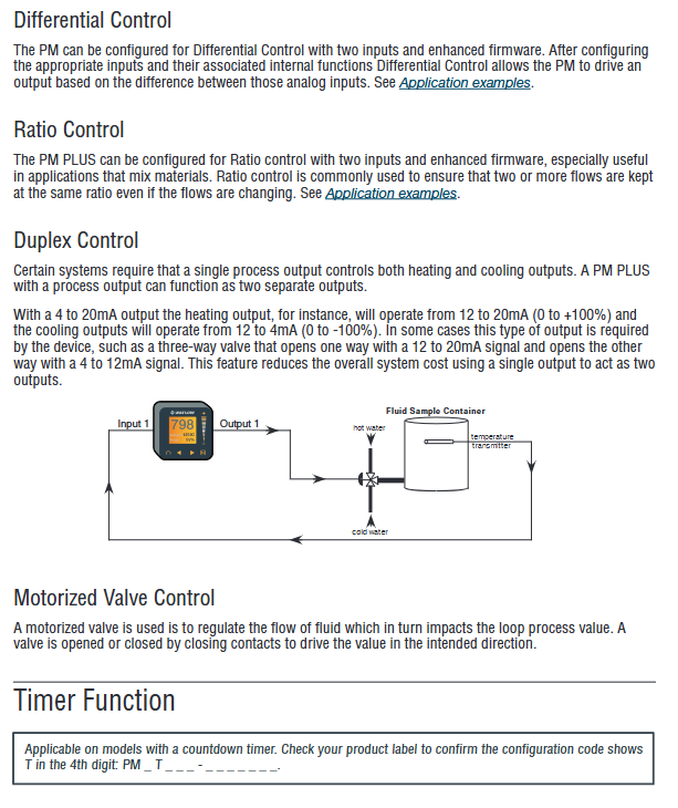
Duplex: Single process output simultaneously controls heating/cooling (such as 4-20mA signal, 12-20mA corresponds to heating, 4-12mA corresponds to cooling), suitable for three-way valve control.
Retransmit: Transmit process values/setpoints to other devices (such as PLCs, recorders) through analog outputs, supporting Scale Low/High and Range Low/High configurations.
3. PID Control and Advanced Algorithms
(1) Core control mode
Support multiple control algorithms to adapt to different process requirements:
Basic modes: On Off (switch control), P (proportional), PI (proportional integral), PD (proportional derivative), PID (proportional integral derivative).
Special mode:
Ratio control: maintains a fixed ratio of two inputs (such as fuel/air mixture ratio), suitable for combustion systems.
Differential control: controls the difference between two inputs (such as the temperature difference between the inlet and outlet of a heat exchanger), suitable for temperature compensation scenarios.
Square Root Control: Performing square root conversion on input signals, suitable for flow measurement (due to the square root relationship between flow rate and differential pressure).
(2) Optimization function
Auto Tune: By driving the process with 100% power output, it automatically calculates the optimal PID parameters (proportional band, integration time, differentiation time), supports 90% set point tuning (to avoid overheating risks), and displays "Tuning 1" on the screen during tuning.
TRU-TUNE+ ® (Adaptive tuning): Real time monitoring of process value fluctuations, dynamic adjustment of PID parameters, adaptation to load changes (such as increased material during heating), supporting 1-6 levels of gain (level 1 is the most sensitive, level 6 is the most stable).
Manual tuning: The proportional band (0.001-9999.000 ° F/° C), integration time (0-9999 seconds), and differentiation time (0-9999 seconds) can be manually adjusted, suitable for complex processes that Auto Tune cannot meet.
4. Program control (Ramp/Soak)
Support 4 program files, each with 10 steps, to achieve automated process curve control (such as material annealing, food sterilization):
(1) Basic Program Configuration
Global settings:
Slope type: time mode (from current value to target value within a fixed duration), rate mode (heating/cooling by ° F/° C per minute).
Program type: Set point trigger (based on controller set point start), process value trigger (based on sensor detection value start).
Guaranteed Soak Deviation: 0.0-9999.000 ° F/° C, the process value needs to enter the deviation zone before timing starts to ensure process uniformity.
(2) Step type and editing
Step Type Function Description Configuration Items
Time: Ramp up to the target value, target set point, hour/minute/second according to the set time
Soak to maintain target value for a fixed duration and event output status (On/Off)
Wait for Event: Wait for digital input to trigger (such as external switch closed), trigger source (DIO 5/6), trigger status (On/Off)
Wait for Process Value: Wait for the process value to reach the target value, target value, and deviation band
Jump to the specified step and repeat the target step number and number of repetitions (0=infinite loop)
End: After the program ends, execute the action. End type (Off/Hold/User, such as Hold maintaining the last set point)
(3) Program startup and control
Startup methods: manual panel startup (Operations → Profile → Profile Start), function key triggering (pre configured), digital input triggering (DIO 5/6), remote communication startup (such as Modbus command).
Operation monitoring: The main screen displays the current step, remaining time, target set point, and supports pause/resume/terminate operations.
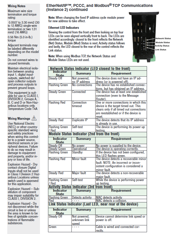
5. Communication and Data Interaction
Support multi protocol communication for easy integration into industrial control systems (such as PLC, SCADA):
(1) Communication Protocol and Parameters
Protocol type interface and parameter applicable scenarios
Modbus ® RTU EIA-485/232, Address 1-247, baud rate 9600/19200/38400bps, parity check Non/Even/Odd small network (such as 16 controllers networking)
Modbus ® TCP Ethernet interface, supports DHCP/fixed IP, 10/100Mbps large factory network, remote monitoring and configuration
EtherNet/IP ™ Compatible with ODVA standard, supports implicit/explicit communication, input/output assembly up to 40 members Rockwell PLC integration
DeviceNet ™ Node address 0-63, baud rate 125/250/500kbps, supports Quick Connect industrial field equipment networking (such as sensors and actuators)
PROFIBUS DP address 0-126, baud rate 12Mbps max, supports DP-V0/DP-V1 Siemens PLC integration, high-speed real-time control
Bluetooth (optional) compatible with EZ-LINK ™ app, Support remote configuration and monitoring (exclusive to 1/16 DIN models) on-site debugging to avoid opening operations
(2) Data interaction function
Register mapping: Supports Modbus programmable memory blocks (40 parameter pointers), customizable common parameter addresses (such as setpoints, procedural values), and facilitates fast read and write operations.
Retransmission function: Transmit process values/setpoints to third-party devices (such as recorders, PLCs) through analog outputs (0-10VDC/0-20mA), supporting scaling and range adjustment.
Event notification: Send alarm, limit, program status and other events through communication for remote troubleshooting.
6. Safety and alarm functions
(1) Limit Control
Function positioning: Independent of PID control for safety protection, supporting high/low limit monitoring, cutting off output and locking after triggering, requiring manual reset.
Configuration item:
Limit type: high limit, low limit, dual limit (simultaneously monitoring high/low).
Reset methods: manual panel reset, digital input triggered reset, remote communication reset.
Linkage action: After triggering, the program can be terminated, PID calculation can be frozen, and associated output can be closed to ensure the safety of equipment and personnel.
(2) Alarm system
Alarm type: 4-channel independent alarm, supporting process alarm (high/low threshold), deviation alarm (deviation from set point), and fault alarm (sensor failure, heater failure).
Alarm characteristics:
Latch/Non Latch: Latch alarms need to be manually cleared, while non latch alarms are automatically cleared after the process value returns to the safe range.
Delay trigger: adjustable from 0-9999 seconds to avoid false alarms caused by instantaneous fluctuations (such as temperature jumps caused by voltage fluctuations in the power grid).
Shielding function: Supports masking alarms during startup and set point changes to avoid false triggering in the early stages of the process.
Installation and Configuration Guide
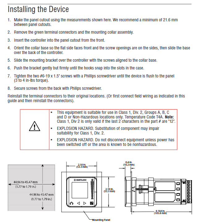
1. Installation process and specifications
(1) Physical installation
Panel openings: Drill holes according to dimensions of 44.96-45.47mm (width) × 53.3mm (height), with a spacing of ≥ 21.6mm between adjacent devices (to avoid heat dissipation effects).
Controller fixed:
Insert the controller from the front of the panel, and install a ring on the back to fit the controller, ensuring that the plane faces the front.
Align the mounting bracket with the mounting ring screw hole and gently press until the buckle is inserted into the housing slot.
Use a Phillips screwdriver to tighten 2 # 6-19 × 1.5 inch screws with a torque of 3-4 in lbs, ensuring that the controller is securely attached to the panel.
Terminal connection:
Remove the green terminal connector and connect the power, input, and output wires (supporting 12-30 AWG wires) according to the wiring diagram.
The terminal torque is 5.0 in lb to avoid poor contact caused by looseness and damage to the terminal caused by tightness.
(2) Wiring specifications and safety
Electrical isolation: Analog input 1, digital I/O, and DC switch output need to be electrically isolated from process output to prevent grounding loops.
Dangerous area wiring: Class 1, Div. 2 areas require the use of certified switches (such as explosion-proof types) to avoid component replacement (which may affect the explosion-proof level). After power failure, plug and unplug the wiring.
Power wiring: For high-voltage versions, it is necessary to distinguish between live wire (L), neutral wire (N), and ground wire (PE), while for low-voltage versions, attention should be paid to positive and negative polarity to avoid reverse connection and equipment damage.
2. Core configuration steps
(1) Quick start configuration (default parameters)
If using the default input type (J-type thermocouple) and control mode (heating PID), it can be directly started:
Connect the sensor (J-type thermocouple), heater (connected to Output 1), and power supply.
After power on, the main screen displays the process value (current temperature) and the set point (default 75 ° F).
By using the panel slider or ± key to modify the set point, Output 1 will drive the heater according to the PID algorithm to bring the process value closer to the set point.
(2) Custom configuration (taking temperature control as an example)
Input configuration:
Path: Operations → Setup → Analog Input → Sensor Type, select "Thermocouple", TC Linearization select "K" (if using K-type thermocouple).
Configure Filter (e.g. 0.5 seconds) to reduce signal fluctuations.
Output configuration:
Path: Operations → Setup → Output → Output 1 → Function, select "Heat", Time Base Type select "Fixed Time Base" (fixed cycle of 1.0 second).
PID control configuration:
Path: Operations → Setup → Control Loop → Heat Algorithm, select "PID".
Execute Auto Tune: Operations → Autotune → Select 'Yes', the controller automatically calculates PID parameters.
Alarm configuration:
Path: Operations → Setup → Alarm → Alarm 1 → Type Select "Process Alarm", set High Set Point to "200 ° F" (high alarm threshold), and Hysteresis to "5 ° F" (hysteresis).
(3) Program Configuration (Ramp/Soak Example)
Taking "Heating up to 150 ° F (30 minutes) → Holding for 60 minutes → Cooling down to 50 ° F (20 minutes)" as an example:
Global settings:
Path: Operations → Setup → Global → Ramp Type, select "Time" (time mode).
Set Guaranteed Soak Enable to "Yes" and Guaranteed Soak Dev. 1 to "2 ° F" (immersion deviation zone).
Step editing:
Step 1 (Ramp): Path → Operations → Profile → Profile 1 Step 1 → Step Type Select "Time", Set Target Set Point to "150 ° F", Hours=0, Minutes=30, Seconds=0.
Step 2 (Soak): Select "Soak" as the Step Type, with Hours=0, Minutes=60, and Seconds=0.
Step 3 (Ramp): Select "Time" for Step Type and set the Target Set Point to "50 °" F”,Hours=0,Minutes=20,Seconds=0。
Step 4 (End): Select "End" for Step Type and "Hold" for End Type (the final set point for insulation).
Start the program: Path → Operations → Profile → Profile Start, select "Profile 1", and the program will start running.
Key points of operation and maintenance
1. Daily operations
(1) Main screen operation
Parameter viewing: The main screen defaults to displaying process values (top column) and set points (bottom column), and can be switched to display output power percentages (such as theme 2/3) through "Home Screen Themes".
Setpoint modification: Simply slide the screen slider or press the ± key to adjust, long press the ± key to quickly increase or decrease (such as quickly adjusting from 75 ° F to 150 ° F).
Mode switching: Path → Operations → Control Mode, switch between Auto, Manual, Off, and directly set the output power (0-100%) in Manual mode.
(2) Program control operation
Program start/pause: Select "Start/Pause" through Function Key (pre configured as "Profile Start/Stop") or panel path ->Operations ->Profile ->Profile Action Request.
Step monitoring: The main screen displays the current step (such as "Step 2 Soak") and the remaining time (such as "00:50:30"), and detailed step information can be viewed through "Profile Status".
Emergency termination: Long press Function Key (if configured as "Profile End") or Path → Profile Action Request, select "End", the program terminates and executes the End Type action.
2. Maintenance and Calibration
(1) Regular maintenance
Cleaning: Wipe the front panel with a dry cloth every month (avoid using corrosive cleaning agents such as alcohol), and check the terminal wiring for looseness every quarter (power off operation).
Sensor inspection: Verify the accuracy of the sensor every six months (such as comparing the displayed value of the controller with a precision constant temperature bath), and adjust the "Calibration Offset" when the deviation exceeds the limit.
Output test: Every year, test the output continuity in the shutdown state (such as connecting Output 1 to the indicator light, setting 50% power in manual mode, and observing whether the indicator light is on or off normally).
(2) Input calibration (taking thermocouple as an example)
Prepare a precision signal source (such as a calibrator that can output J-type thermocouple signals) and a precision multimeter.
After power failure, disconnect the sensor wiring and connect the calibrator to the Analog Input 1 terminal (T1/S1/R1).
After power on, enter calibration mode: Path → Operations → Factory → Calibration → Electrical Input Offset/Slope.
Calibrate low range: The calibrator outputs "0mV" (corresponding to 0 ° C), reads the controller's "Electrical Measurement" value, calculates and inputs the "Electrical Input Offset".
Calibrate high range: The calibrator outputs "50mV" (corresponding to approximately 1000 ° C), reads the "Electrical Measurement" value, calculates and inputs it into the "Electrical Input Slope".
Verification: The calibrator outputs "25mV" (intermediate value), and the controller display value should be consistent with the corresponding value of the calibrator (deviation ≤ 0.1%).
3. Troubleshooting
(1) Common faults and solutions
Possible causes and solutions for the fault phenomenon
No display power supply not connected, fuse burned out, loose terminals. Check the power supply wiring, replace the fuse (if any), and re tighten the terminals
Sensor no reading (display "----") Sensor open/short circuit, input type configuration error. Check sensor wiring, replace sensor, reconfigure "Sensor Type"
No output action control mode is set to "Off", output function configuration error, load fault switch to "Auto/Manual" mode, reconfigure "Output Function", check load (such as heater resistance)
Severe temperature overshoot, improper PID parameters, failure to execute Auto Tune, re execution of Auto Tune, manual increase of proportional band or integration time
Communication failure address/baud rate mismatch, wiring error, terminal resistance not connected. Check communication parameters, check EIA-485 wiring (A/B lines), and connect 120 Ω terminal resistors at both ends of the bus
(2) Alarm troubleshooting process
Alarm recognition: The main screen alternately displays alarm information (such as "Alarm High 1"), path → Operations → Alarm → Alarm 1 → Alarm State to view detailed status (such as "High").
Root cause analysis:
If it is "Alarm High": Check whether the process value exceeds the "High Set Point" and whether there is any abnormal load (such as continuous power on of the heater).
If it is an "Input Error": Check if the sensor wiring is loose and if the sensor is damaged (such as a broken thermocouple).
Treatment measures:
Process abnormality: troubleshoot the load (such as replacing the heater), and clear the alarm after the process value returns to the safe range (path → Alarm → Clear Alarm).
Sensor malfunction: Replace the sensor. If "Input Error Latching" is enabled, manually clear the error (path → Analog Input → Input Error Latching → Off, then switch back to On).
Typical application scenarios and configuration examples
1. Single loop temperature control (industrial oven)
demand
Control the oven temperature at 180 ° C ± 2 ° C, with a heating power of 10kW and a K-type thermocouple sensor. High alarm (200 ° C) and low alarm (160 ° C) are required.
Configuration steps
Input: Analog Input 1 → Sensor Type=Thermocouple, TC Linearization=K, Filter=1.0 seconds.
Output: Output 1 → Function=Heat, Type=NO-ARC Relay (15A), Fixed Time Base=5.0 seconds.
PID control: Heat Algorithm=PID, execute Auto Tune (target set point 180 ° C).
Alarm: Alarm 1 → Type=Process Alarm, High Set Point=200 ° C, Low Set Point=160 ° C, Hysteresis=2 ° C, Latching=Yes.
2. Sensor backup control (medical sterilization equipment)
demand
The sterilization temperature needs to be stable at 121 ° C. The main sensor is RTD (3-wire system), and the backup sensor is J-type thermocouple. When the main sensor fails, it will automatically switch to the backup sensor.
Configuration steps
Input:
Analog Input 1 (main) → Sensor Type=RTD, RTD Leads=3, Resistance Range=100 Ω.
Analog Input 2 (backup) → Sensor Type=Thermocouple, TC Linearization=J.
Path → Operations → Setup → Process Value → Function=Sensor Backup,Source Function A=Analog Input 1,Source Function B=Analog Input 2。
Output: Output 1 → Function=Heat, Type=SSR (0.5A), drives an external solid-state relay to control the heating tube.
Limit protection: Limit 1 → High Set Point=130 ° C, Low Set Point=110 ° C, Reset Source=Digital Input 5 (manual reset button).
3. Slope/constant temperature process (material heat treatment)
demand
Process curve: Room temperature → 100 ° C (heating for 30 minutes) → 100 ° C insulation for 60 minutes → 150 ° C (heating for 20 minutes) → 150 ° C insulation for 120 minutes → cooling to 50 ° C (cooling for 40 minutes).
Configuration steps
Global settings: Ramp Type=Time, Guaranteed Soak Enable=Yes, Guaranteed Soak Dev. 1=1 ° C.
Program editor:
Step 1: Time type, Target=100 ° C, Time=30 minutes.
Step 2: Soak type, Time=60 minutes.
Step 3: Time type, Target=150 ° C, Time=20 minutes.
Step 4: Soak type, Time=120 minutes.
Step 5: Time type, Target=50 ° C, Time=40 minutes.
Step 6: End Type, End Type=Off (shutdown after cooling down).
Startup method: Function Key is configured as "Profile Start" to start the program with one click.
Appendix Key Information
1. Configuration code analysis
14 bit configuration code defines the hardware and functional options of the controller, for example: PM6C2CAEAALFJWP
Explanation of Example Values for Rank Meaning
1-2 Product Series PM=PM PLUS ™ series
3 package size 6=1/16 DIN
4 core functions C=PID controller with universal input
5 power supply and I/O 2=100-240VAC+2 digital I/O channels
6-7 output 1/2 CA=Output1=DC switch, Output2=None
8 Communication options E=EIA-485 Modbus ® RTU+Bluetooth
9 Auxiliary Function A=None
10-11 output 3/4 LJ=Output3=None, Output4=Mechanical Relay (Form A)
12 model selection F=Enhanced firmware (including ratio/difference control)
13-14 Custom Options WP=Front Panel with Watlow Logo
2. Compliance Statement
CE Compliance: Compliant with the 2014/30/EU (EMC), 2014/35/EU (low voltage), and 2014/53/EU (wireless, Bluetooth models) directives.
Dangerous area: Class 1, Div. 2 models must meet the ANSI/ISA 12.12.01-2007 standard, temperature code T4A, and cannot be used in Class 1, Div. 1 areas.
RoHS/WEEE: Complies with the 2011/65/EU RoHS 2 directive, and must be recycled according to local regulations when discarded (including button batteries, which need to be recycled separately).
- OMRON
- ABB
- General Electric
- EMERSON
- Honeywell
- HIMA
- ALSTOM
- Rolls-Royce
- MOTOROLA
- Rockwell
- Siemens
- Woodward
- YOKOGAWA
- FOXBORO
- KOLLMORGEN
- MOOG
- KB
- YAMAHA
- BENDER
- TEKTRONIX
- Westinghouse
- AMAT
- AB
- XYCOM
- Yaskawa
- B&R
- Schneider
- KONGSBERG
- NI
- WATLOW
- ProSoft
- SEW
- ADVANCED
- Reliance
- TRICONEX
- METSO
- MAN
- Advantest
- STUDER
- DANAHER MOTION
- Bently
- Galil
- EATON
- MOLEX
- DEIF
- B&W
- ZYGO
- Aerotech
- DANFOSS
- Beijer
- Moxa
- Rexroth
- Johnson
- WAGO
- TOSHIBA
- BMCM
- SMC
- HITACHI
- HIRSCHMANN
- Application field
- XP POWER
- CTI
- TRICON
- STOBER
- Thinklogical
- Horner Automation
- Meggitt
- Fanuc
- Baldor
- SHINKAWA
- Other Brands
- UniOP
- KUKA
- Iba
- Beckhoff
-
 Basler D90 96801 100 PCB Card
 -
 Basler XR2002F Voltage Regulator (110 VAC, 48-480 Hz)
 -
 Basler SR8A-2B14B3A Regulator
 -
 Basler 9561500100 Module
 -
 Basler DECS-400 BE1-11 System
 -
 Basler DECS-100-B15 Excitation Control
 -
 Basler SCP 210 Frequency Controller
 -
 Basler SR4A-2B15B3A Static Voltage Regulator
 -
 Basler BE1-32R Power Relay
 -
 Basler PIA2400-17GM Power Interface Adapter
 -
 Basler MVC 232 Manual Voltage Control Module
 -
 Basler SSR 32-12 Static Voltage Regulator
 -
 Basler 5MW AVR Generator Voltage Regulator
 -
 Basler VR63-4B Voltage Regulator
 -
 Basler DECS-100-A05 AVR for Engine Generator
 -
 Basler DECS-100-B15 Automatic Voltage Regulator
 -
 Basler BE1-32R Directional Power Relay
 -
 Basler BE1-87B Differential Relay
 -
 Basler UFOV 260A Protective Module
 -
 Basler 9-2614-02-100 PCB Rev M
 -
Basler DECS-100-B15 Digital AVR
-
 Basler 9284900103 PS DECS-400N
 -
 Basler D4N3H1U Intertie Protection
 -
 Basler DECS-100-B15 A15 AVR
 -
 Basler KR4F Voltage Regulator
 -
 Basler BE26434 T14 Transformer
 -
 Basler SR8A-2B15B3A Regulator
 -
 Westinghouse 774B472A12 AR Relay
 -
Basler DECS-100-B15 AVR
-
Basler XR2002F Regulator 110V
-
Basler SR125-E Static Regulator
-
 Basler SSR 125-12 Regulator
 -
 Basler MOC2599 Motor Pot
 -
 Basler BE1-DFPR Feeder Relay
 -
 Basler CBS 305 Current Boost
 -
 Basler BE1-25 AutoSync
 -
 Basler MVC 300 Voltage Control
 -
 Basler BE3-25A AutoSync
 -
 Basler KR7FF Static Regulator
 -
 Basler 90-49000-100 Regulator
 -
 Basler 880 kVA Dry Type Transformer Specs
 -
 Basler Electric BE1-25 Sync-Check Relay Specs
 -
 Basler SSR 125-12 Voltage Regulator Specs
 -
 Basler Electric BE1-851 Overcurrent Relay Review
 -
Basler Electric 149D930G02 Control Sub-Assembly
-
 Basler Electric BE1-81O/UT Frequency Relay Specs
 -
 Basler Electric BE1-51/27C Overcurrent Relay
 -
 Basler Electric 149D956G02 Industrial Component
 -
Basler Electric BE1-51A Overcurrent Relay Specs
-
 Basler Electric BE1-40Q Loss of Excitation Relay
 -
 Basler DECS-200 Excitation Control System
 -
 Basler DECS-200 Voltage Regulator 56-277V AC / 125V DC
 -
Basler BE1-87T Transformer Differential Relay
-
 Basler RDP-110-S1 Protection Relay
 -
 Basler BE1-700V Digital Protective Relay
 -
 Basler BE1-951 Overcurrent Protection System
 -
 Basler DECS-300 Digital Excitation Control
 -
 Basler DECS-200 Digital Excitation Control
 -
 Basler DECS-200-1C Excitation Control System
 -
Basler DECS-200-1L Digital Excitation Control
-
 Basler Electric BE1-GPS Generator Protection System
 -
Basler Electric DECS-200-1C Digital Excitation Controller
-
 Basler Electric DECS125-15 Excitation Control with Power Module
 -
 Basler Electric BE1-87G Differential Relay
 -
 Basler Electric BE1-11 Protection System I5A3M2P2N0EA00
 -
Basler Electric DECS-200-1C Excitation Control System
-
Basler Electric BE1-11g Generator Protection Relay
-
Basler Electric DECS 125-15-B2C1 V2.0.9 Excitation Control
-
 Basler Electric BE1-81O/UT3ED1JA7N2F Frequency Relay
 -
Basler Electric BE1-81O/UT3EE1YB7N1F Frequency Relay
-
 Basler Electric DECS-200-1L Digital Excitation Control System
 -
Basler DECS125-15-B2C1 Excitation Control
-
 Basler 9507900205 SSR Retrofit Voltage Regulator
 -
 Basler BE2000E Digital Voltage Regulator
 -
 Basler BE1-GPS Generator Protection System
 -
Basler DECS-250-CN1CN1N Digital Excitation Control
-
 Basler DGC-2020 Genset Controller
 -
 Basler BE1-81O UT3ED1LA7N0F Frequency Relay (Variant)
 -
 Basler BE1-81O UT3EE1YA9S0F Frequency Relay (Variant)
 -
Basler BE1-81O Over/Under Frequency Relay
-
Basler DECS125-15 Digital Excitation Control
-
Basler Electric BE1-951 Overcurrent Protection System
-
 Basler Electric BE1-700V Digital Protective Relay
 -
 Basler Electric APR63-5 Automatic Voltage Regulator
 -
Basler Electric BE1-851 Overcurrent Protection System
-
Basler Electric DECS-250-LN1SN1N Excitation Control
-
 Basler Electric BE1-87T Transformer Differential Relay
 -
Basler Electric DECS-200-1L Excitation Control System
-
 Basler Electric 9310300100 DECS-300 Excitation Control
 -
 Basler Electric SSE-N 125-4.5KW Shunt Exciter Regulator
 -
 Basler Electric DGC-2020HD-5NS1DNSBA Genset Controller
 -
Basler Electric BE1-81-O/UT3EE1JB7N1F Frequency Relay
-
Basler Electric BE1-81T1EE1WA0N1F Frequency Relay
-
 Basler Electric BE1-25M1EA6PN5R1F Sync-Check Relay
 -
 Basler Electric BE1-GPS Generator Protection System
 -
Basler Electric DECS-250-LN1SN1N Excitation Control Rev V
-
 Basler Electric DECS-250-CN2CN1N Excitation Control
 -
Basler Electric BE1-50/51B-207 Overcurrent Relay
-
Basler Electric DECS-300-C0N0 Excitation Control System
-
Basler Electric DECS-200 Digital Excitation Control System
-
Basler Electric DECS-250-LN1CN1N Excitation Unit
-
Basler Electric DECS-250 LN2SA1D Excitation Unit Specs
-
Basler Electric BE1-87T Transformer Relay Review
-
Basler Electric BE1-11 Protection System
-
Basler Electric BE1-GPS100-E4N1H1N Protection System
-
 Allen-Bradley 442G-MABH-R Safety Module
 -
 Beckhoff CX1030-0111 PLC Assembly Profile
 -
 FANUC IC693CPU364 PLC Module
 -
 Orange Denmark Type 200816 220 PLC Specs
 -
 OMRON C200H-SNT31 Sysmac PLC Module
 -
 Allen Bradley 20AB022A3AYNANC0 PowerFlex 70
 -
 OMRON C200HW-PCU01 Position Control Unit
 -
 ABB AO845A-eA Analog Output Module
 -
 OMRON CJ1M-CPU22 CPU Unit
 -
 Allen Bradley 100-E265ED11 Contactor
 -
 Honeywell 51304511-100 Interface Module
 -
 SOLEXY BXF3S0101N0018 Gateway Module
 -
 OMRON CJ2H-CPU65 CPU Unit
 -
 Automation Direct GS2-45P0 AC Drive
 -
 M68-2000 2-Axis Motion CNC Controller
 -
 OMRON CJ1M-CPU11 V3.0 PLC CPU Unit
 -
 OMRON CJ1W-NC413 4-Axis Positioning Controller
 -
 OMRON 3G2A3-PRO16 Programming Console HMI
 -
 Siemens 3VT8440-2AA04-2GA2 Molded Case Circuit Breaker
 -
 Siemens 3RT5045 Contactor Series
 -
 OMRON C200HS-CPU01-E SYSMAC PLC Controller
 -
 OMRON C500-NC103-E Positioning Control Unit
 -
 OMRON CJ1W-TC001 Temperature Control Unit


