
Watlow Power Series microprocessor based SCR power controller
Watlow Power Series microprocessor based SCR power controller
Product Core Overview
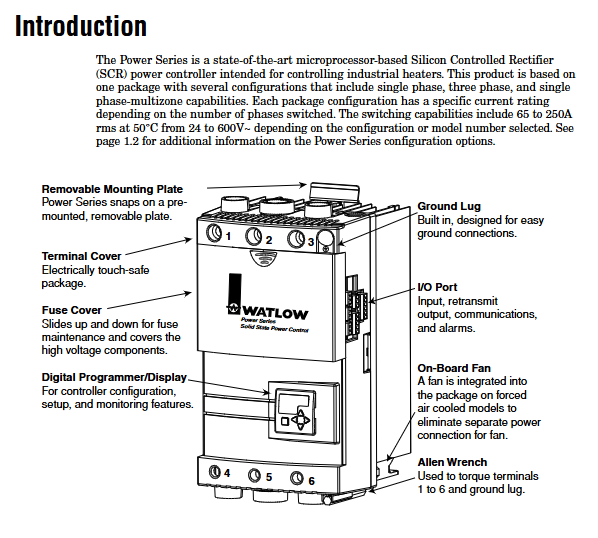
The Watlow Power Series is a microprocessor based silicon controlled rectifier (SCR) power controller designed specifically for industrial heater control. It supports various configurations such as single-phase, three-phase two bridge arm, three-phase three bridge arm, and single-phase multi zone. The current rating is 65-250A (at 50 ° C environment), and the voltage is compatible with 24-600V AC. It has multiple control methods such as zero crossing trigger and phase angle control. It integrates heater diagnosis, current limitation, alarm and other functions, and is widely used in industrial heating, heat treatment, semiconductor manufacturing and other scenarios. The product complies with UL 508, CE certification, IP00 protection level, pollution level 3, provides a 3-year warranty, supports Modbus RTU communication and signal retransmission function, and balances stability and flexibility.
Core advantages:
Multi configuration adaptation: covering single-phase, three-phase, and multi zone control, meeting the needs of different load types (resistive, transformer coupled loads).
Intelligent control function: supports zero crossing (fixed/variable time base), phase angle control, built-in soft start, current limit, heater drying and other functions to protect the load and optimize the control effect.
Comprehensive diagnosis and alarm: equipped with multiple alarms such as heater open circuit, over temperature, phase imbalance, etc., supporting locked/non locked modes, combined with SCR short circuit detection and fuse protection, to enhance system safety.
Flexible expansion: optional communication module (RS-232/485), signal retransmission function, supports remote monitoring and parameter configuration.
Product Configuration and Function Detailed Explanation
(1) Core configuration type
The Watlow Power Series offers 5 core configurations, covering different phase and area control requirements, with specific differences as follows:
Configuration Type Phase/Region SCR Quantity Applicable Load Critical Limitations
Single Phase, 1 Phase, 2 Resistive, Transformer Coupled Load Current Rated Maximum( 250A@50 ° C), supports all control modes
Three phase two bridge arm (3-phase 2-Leg), 3-phase (switching only L1/L3), 4-phase delta/ungrounded resistive load only supports zero crossing control, no heater drying/current limitation
Three phase three bridge arm (3-phase 3-Leg), 3-phase (switch all), 6-phase grounded/ungrounded wye, delta load support all control modes, can be equipped with heater diagnosis
2-Zone Single Phase, 2 independent single-phase zones, 4 (2 per zone), multi zone independent resistive load sharing alarm output, with a unified control method
3-Zone Single Phase, 3 independent single-phase zones, 6 (2 per zone), multi zone independent resistive load sharing alarm output, with a unified control method
(2) Deep analysis of key functions
1. Heater Diagnostics function
Only applicable to single-phase and three-phase three bridge arm configurations, requiring separate selection (marked with "1" in the model), core functions include:
Heater Bake Out:
Principle: Slowly increase the power during startup (soft start), remove the moisture absorbed by the heater, and avoid insulation breakdown or fuse tripping caused by direct full power.
Configuration parameters: drying time (0-9999 minutes, default 1440 minutes), drying overcurrent threshold (HbOC, 0-rated load current, default 10% load current).
Trigger logic: If the current exceeds HbOC during the drying process, it will trip and display an error message of "HbOC"; Automatically switch to the preset control mode after drying is completed.
Current Limiting:
Only the phase angle control mode is effective, and the load current does not exceed the set value (CL ` A parameter) through power increment adjustment of 0.1%/AC cycle.
Application scenario: When a transformer is coupled with a load (such as a silicon carbide rod) during startup, avoid excitation inrush current and protect SCR and the load.
Load monitoring:
Open circuit detection: When the power is above 20% and the current is ≤ 2A, the "Open" alarm is triggered.
Tolerance detection: When the current is below [tol_] or above [tol -] (effective at 20% power or above), the "tol" alarm is triggered, and the load imbalance percentage (ldif, default 100%) can be set.
2. Comparison of control methods and application scenarios
Control mode, working principle, advantages, disadvantages, applicable scenarios
Zero crossing - allocate complete power cycle within a fixed time base and period (1/4 second), such as 40% power=24 cycles on+36 cycles off (60Hz/1 second), low noise (RFI), small load impact, slow response speed (period level), resistive heaters (such as nickel chromium), and noise sensitive scenarios
Zero crossing - dynamic adjustment of on-off cycle with variable time base (1 cycle increment), fast response of line voltage compensation, high power resolution, long heater life, slightly higher noise than resistive loads with fixed time base that require frequent power adjustment
Phase angle control controls the conduction angle of SCR within the power cycle (0-180 °), achieving extremely fast continuous power regulation response (cycle level), supporting soft start/current limiting noise (RFI), high harmonic pollution, transformer coupling load, and nonlinear loads that require precise temperature control
The DC contactor mode has only 0%/100% output, triggering threshold of 2.0V/3.5V (voltage), 5.0mA/8.0mA (current), and simple control. It is suitable for heating scenarios without power regulation capability and only requires on-off control (such as insulation)
3. Alarm system and security protection
Alarm type and triggering conditions:
Suggestions for handling the triggering conditions of alarm identification
[Open] If the heater has an open circuit of 20% or more power and the current is ≤ 2A, check the wiring and resistance value of the heater
[tol] If the load tolerance current exceeds the range of [tol_] - [tol –] (above 20% power), check for heater aging or short circuit, and adjust the tolerance threshold
[` OT] Heat sink overheating Heat sink temperature>factory set value ([sd Ç `]) Clean the heat sink, optimize chassis cooling, check the fan
[line] Line voltage loss, zero crossing signal loss, voltage<1/2 of reference voltage, polarity error. Check the power supply wiring and voltage, and view the specific fault type through the diagnostic menu ([diAg])
[p bal] Phase imbalance. If the difference in three-phase current exceeds the set value (ldif), check the three-phase load and wiring to ensure phase balance
[Dog] Communication watchdog timeout without communication ([` seC] parameter setting) Check the communication wiring and parameters to confirm that the main device is normal
Flexibility of alarm configuration:
Global mode: Set all alarms to "Standard (Std)/Locked (Lat)/Silent (Sil)/Locked+Silent (LaSI)" through the [glblbl] parameter.
Individual configuration: When [glbl] is set to "Off", each alarm type can be configured separately to meet different security level requirements.
Relay status: Select the "power on (alC)" or "power off (alO)" of the relay when the alarm is triggered through the [a | lgc] parameter, and the default power off trigger is triggered (safer, avoiding missed reporting in case of power loss).
4. Communication and signal retransmission
Modbus RTU communication:
Hardware interface: RS-232 (single device) or RS-485 (multiple devices, up to 247 units, requiring repeaters), isolated design to prevent interference.
Core parameters: device address (1-247), baud rate (1200/2400/4800/9600/19200bps), data format (8N1, fixed), watchdog timeout (0-9999 seconds, 0 disabled).
Register function: Supports reading input/output values (such as [` In], [` Out]), configuration parameters (such as control algorithms, alarm modes), diagnostic information (such as error codes), and can read up to 32 registers at a time.
Signal Retransmit:
Applicable conditions: Both heater diagnosis and retransmission functions (marked with "1" and "1" in the model) need to be selected simultaneously.
Configuration steps:
Select the retransmission type ([type]): current ([CUr]) or power ([Hua]).
Select the retransmission phase/region (phas/one), three-phase equipment only supports single region.
Scaling range: If 4-20mA corresponds to 50-250A current, [Cur_]=50 and [Cur -]=250 need to be set.
Accuracy guarantee: current retransmission resolution of 5 μ A, voltage retransmission resolution of 2.5mV, temperature stability of 100ppm/° C.
Installation and wiring specifications
(1) Preparation before installation
Environmental assessment:
Temperature: Ensure that the maximum temperature inside the chassis is ≤ 50 ° C (reference record), and additional cooling equipment (such as fans and eddy current coolers) is required if it exceeds this limit.
Space: Vertical installation, with 9 inches (228.6mm) of space reserved at the top/bottom to achieve the "chimney effect" heat dissipation; When multiple units are installed in parallel, the spacing should be ≥ 305mm (12 inches) to avoid thermal stacking.
Pollution: Avoid corrosive gases, oil mist, and high dust environments. If unavoidable, protective enclosures (IP54 or above) should be installed.
Tools and accessories:
Installation tools: Phillips # 3 screwdriver, 3/8-inch hex wrench (terminal torque), torque wrench (180 in lbs range).
Essential accessories: semiconductor fuses (matched by model, such as 65A controller with 100A fuses), grounding wires (with the same specifications as power lines), shielding wires (for communication and signal retransmission).
(2) Detailed installation steps
1. Panel installation (N20-F30 model)
Process panel cuts according to dimensions of 55mm × 55mm (± 0.5mm), with a panel thickness of 1.5-9.7mm.
Fixed mounting plate: Use 4 # 10-1/4 inch screws (provided by the user) to secure the mounting plate to the panel with a torque of 8-10 in lbs.
Install controller: Align the positioning pin on the controller heat sink with the key slot on the mounting plate, push in and press down until the buckle is securely fastened, and confirm that there is no looseness.
2. Bolt fixation (F35 model)
Drill 6 1/4-20 threaded holes according to the drawing, with hole spacing as shown in Figure 2.2aa of the manual.
Use 6 1/4-20 bolts (to be provided by the user) to secure the controller to the mounting surface, with a torque of 18-20 in lbs, to ensure that the heat sink fits snugly onto the mounting surface.
(3) Wiring specifications and examples
1. Power and load wiring (key precautions)
Wire selection:
Material: Only copper wires are allowed, with an insulation level of 90 ° C (NEC standard).
Specification: Choose according to the current, such as 6 AWG for 65A and 250 MCM for 250A. Please refer to Table 6-79 in the manual for details.
Bending radius: The minimum bending radius is 2.0-8.5 inches (depending on the wire specifications) to avoid excessive bending and damage to insulation.
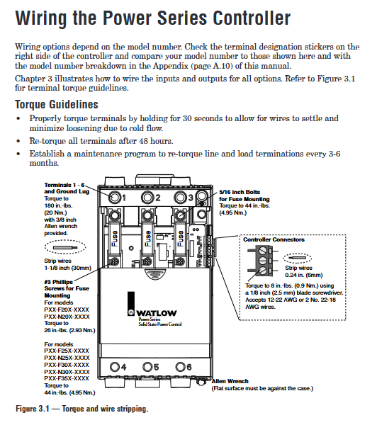
Terminal torque:
Main power/load terminal (1-6 and ground terminal): 180 in lbs (20 Nm), use a 3/8-inch hex wrench and hold for 30 seconds to ensure stable cold current of the wire.
Control signal terminal (10-23): 8 in lbs (0.9 Nm), using a 1/8 inch flathead screwdriver, wire stripping length 6mm (0.24 inches).
Installation of fuses:
Location: Fuse holder inside the controller (requires sliding the fuse cover to open), only use Watlow recommended models (such as 0808-0102 series) or equivalent Bussmann models (such as 170M1317).
Torque: The torque of the fuse bolt is 44 in lbs (4.95 Nm) to avoid poor contact and heat generation.
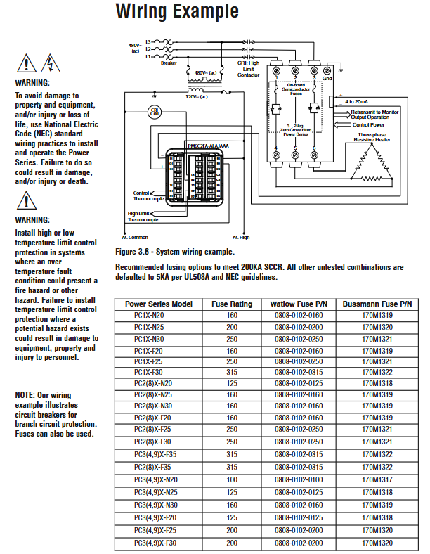
2. Typical wiring example (three-phase three bridge arm configuration)
Power input: L1/L2/L3 is connected to three-phase 480V AC, N is connected to the neutral line (if the load is grounded), and the grounding terminal is connected to the protective grounding (same specifications as the power line).
Load output: Connect U/V/W to a three-phase heater, ensuring that the load is grounded or delta connected, and the phase rotation is clockwise from A-B-C.
Control signal: 4-20mA input terminal 13 (+)/14 (-), common ground terminal 15.
Alarm output: Terminals 17 (NO)/18 (C)/19 (NC) are connected to external alarm lights or PLC inputs, with a rated current not exceeding 3A.
Communication: RS-485 terminal 21 (485 T/R+)/22 (485 T/R -)/23 (GND) is connected to the bus, and the shielding layer is only grounded at the controller end.
3. Anti interference wiring measures
Wiring separation: The distance between the input signal line (control/communication/retransmission) and the power line/load line should be ≥ 305mm (12 inches), and when crossing, it should be at a 90 ° angle to avoid parallel wiring.
Shielding treatment: Control signals and communication lines use shielded twisted pair cables, with the shielding layer grounded at one end (controller end) to avoid grounding loops.
Inductive load suppression: If the load contains inductive components such as contactor coils and solenoid valves, RC suppressors (such as Watlow 0804-0147-0000) need to be connected in parallel to reduce switch noise.
Operation and parameter configuration
(1) Operation interface and navigation
1. Button and display functions
Component Function Description Operation Example
The parameter values (such as input current and output power) are displayed on the upper screen, and the error code "20.0" indicates that the current output power is 20.0%
The lower display screen shows parameter names (such as [` In], [` Out]), and the menu hierarchy displays "[algo]", indicating that the current control algorithm menu is in progress
Adjust parameter values using the addition and subtraction keys (Ó/Î) (short press ± 1, long press to quickly increase or decrease), switch menus, and press the Ó key on the settings page to switch to the next menu
Left and right keys (¬/ ®) Switch parameters within the menu, confirm selection, and press in the [alpha] menu ® Switch to the [Off] parameter with the key
Home button (±) returns to display loop, switches area/phase. Press the ± button on the settings page to return to display loop and view real-time parameters
The alarm indicator light is red and lights up when an alarm is triggered. If the alarm is locked, it needs to be manually cleared. Flashing indicates that the alarm has not been confirmed, while constant light indicates that it has been confirmed
The communication indicator light is green, flashing indicates communication activity. No flashing indicates communication interruption, and the parameters need to be checked
2. Menu structure and navigation path
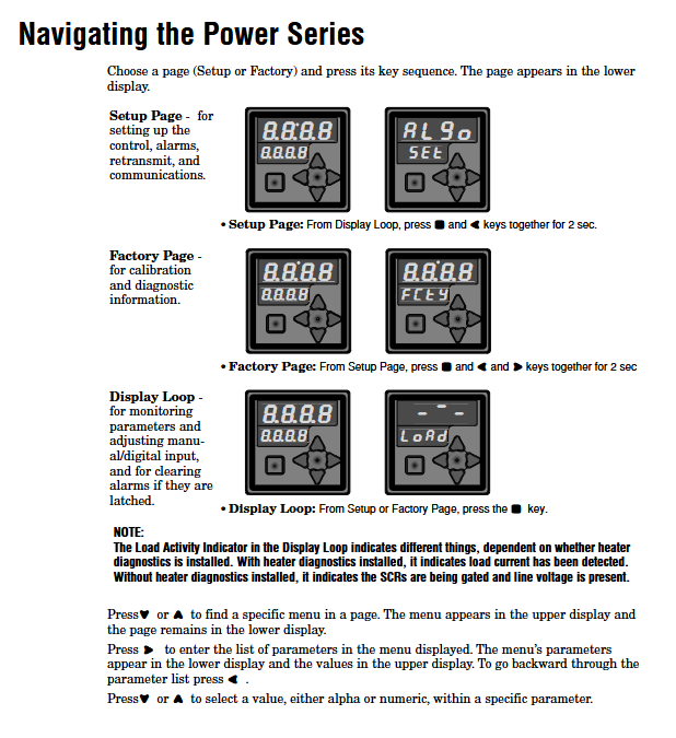
Display Loop: default page for monitoring real-time parameters, path: press the ± key to return from any menu.
Single phase equipment: displays [In] (input signal), [Out] (output power), [UoL] (line voltage), and [Cur] (load current).
Three phase equipment: Press the ± key to switch phases and display the voltage/current of each phase, such as [Uol1]/[Cur1] (L1 phase).
Setup Page: Configure control, alarm, and communication parameters. Path: Display loop. Press and hold the ±+¬ keys for 2 seconds, and the next screen will display "SEt".
Core menu: [alpha] (Control Algorithm), [Ctrl/2/3] (Area Control), [Opt1/2/3] (Area Options), ['arl] (Alarm), [Om] (Communication), [retry].
Factory Page: Calibration, Data Backup, Lock Menu, Path: Settings Page, Long Press ±+¬+ ® Press the key for 2 seconds, and the next screen will display "FCty" (password required).
Core menu: [dAta] (Data Backup/Recovery), [` Loc] (Menu Lock), [InFo] (Device Information), [diAg] (Diagnosis), [In1/2/3] (Input Calibration).
(2) Core parameter configuration steps
1. Control algorithm configuration (taking phase angle control as an example)
Enter the settings page: Press and hold the ±+¬ keys for 2 seconds in the display loop, and the next screen will display "SEt".
Select the [alpha] menu: Press the Ó/Î keys until "[alpha]" appears on the upper screen and "[` set]" appears on the lower screen.
Select phase angle control: Press ® Switch the key to the [` Off] parameter, press the Ó key to change the value to [PH2t], and press the ± key to confirm (controller restart).
Configure soft start: Enter the [Ctrl] menu and press ® Switch the key to the [Soft] parameter and set it to 10 seconds (to avoid startup shock).
Configure current limit: Enter the [Opt1] menu and press ® Switch the key to the [Lili] parameter, set it to "[` ` On]", and then switch to the [ClA] parameter, set it to 110% of the rated load current (such as 110A for a 100A load).
2. Alarm configuration (taking heater open circuit alarm as an example)
Enter the [arr] menu: Press the Ó key on the settings page until "[arr]" appears on the upper screen and "[` set]" appears on the lower screen.
Turn off global alarm: Press ® Switch the key to the [glbl] parameter and set it to "[` Off]" (allows separate configuration).
Configure open circuit alarm: press ® Switch the key to the [Open] parameter and set it to "[LaT]" (locked mode, needs to be manually cleared).
Configure alarm relay: press ® Switch the key to the [a | lgc] parameter and set it to "[al ` O]" (when the relay is powered off during an alarm, it is safer).
Confirm configuration: Press the ± key to return to the display loop, and check the relay status and indicator lights when triggering an alarm.
3. Communication configuration (Modbus RTU)
Enter the [Om] menu: Press the Ó key on the settings page until "[Om]" appears on the upper screen and "[` set]" appears on the lower screen.
Set device address: Press ® Switch the key to the [addr] parameter and set it to 1 (to avoid conflicts with other devices).
Set baud rate: Press ® Switch the key to the [baUd] parameter and set it to 9600 (consistent with the main device).
Enable watchdog: Press ® Switch the key to the [Wd] parameter, set it to "[` ` On]", and then switch to the [seC] parameter, set it to 30 seconds (timeout without communication triggers an alarm).
Test communication: Read register 150 (input current) through Modbus master device (such as PLC) and confirm that the data is normal.
(3) Calibration and Data Maintenance
1. Analog input calibration (taking 4-20mA input as an example)
Enter the factory page: Long press ±+¬ in the settings page+ ® Press the key for 2 seconds, enter the password (contact Watlow to obtain it), and the bottom screen will display "FCty".
Enter the [In1] menu: Press the Ó key until "[In1]" appears on the upper screen and "[FctY]" appears on the lower screen.
Calibration low point: Input a 4.00mA standard signal to the controller and press ® Switch to the [nna_] parameter and adjust the value to 4.00mA.
Calibration high point: Input a 20.00mA standard signal to the controller and press ® Switch to the [nna -] parameter and adjust the value to 20.00mA.
Save Calibration: Press ® Switch to the [CLA] parameter and set it to "[` req]". After 5 seconds, display "[idle]" to indicate calibration is complete.
2. Data backup and recovery
Backup configuration:
Enter the [dAta] menu: Press the Ó key on the factory page until "[dAta]" appears on the upper screen and "[FctY]" appears on the lower screen.
Select backup range: Press ® Switch the key to the [BAUP] parameter, set it to "[all]" (backup all parameters) or "[2n1]" (backup area 1 only).
Perform backup: Press the ± key to confirm, and the display '[idle]' indicates that the backup is complete (stored in the backup EEPROM).
Restore configuration:
Enter the [dAta] menu and press ® Switch to the [rest] parameter and set it to the same range as during backup (such as "[` all]").
Perform recovery: Press the ± key to confirm, and after the controller restarts, the parameters will be restored to the backup values (without overwriting the calibration parameters).
Troubleshooting and Maintenance
(1) Common faults and solutions
Possible causes of fault phenomena (sorted by priority), troubleshooting steps refer to document paragraphs
No display, no output. 1. The power supply is not connected or the voltage is abnormal
2. The main fuse is blown
3. Internal power module failure 1. Measure the voltage of the power terminal (should comply with 24-600V AC)
2. Open the fuse cover and measure the fuse resistance with a multimeter (normal<1 Ω)
3. If there is no power supply, check the wiring. If the fuse is blown, replace it. If it still fails, return it to the factory
Abnormal output power (e.g. In=100% but Out=0%) 1. Control algorithm set to Off
2. Input signal not calibrated or wiring error
3. Load failure or wiring disconnection. 1. Enter the [alpha] menu to confirm that the algorithm is not "Off"
2. Check the input wiring (such as whether the 4-20mA signal is normal) and recalibrate the input
3. Measure the load resistance and confirm that there are no open/short circuits
Overheating alarm for heat sink (OT) 1. Dust accumulation and blockage of heat sink
2. Insufficient cooling of the chassis (fan failure/insufficient space)
3. Overloading of the load causes excessive heating of the SCR. 1. Clean the heat sink fins with compressed air after power failure
2. Check if the fan is running and measure the temperature inside the chassis (should be ≤ 50 ° C)
3. Monitor the Cur parameter and confirm that the load current does not exceed the rated value
Communication failure (no data exchange) 1. Address/baud rate mismatch
2. Communication wiring error (such as 485 ± reversed connection)
3. Communication line interference or distance too far. 1. Confirm that the controller and main device parameters are consistent ([addr], [baUd])
2. Check the RS-485 wiring (21=+, 22=-, 23=GND), exchange ± line test
3. Increase terminal resistance (120 Ω), shorten communication distance or add repeaters
Phase angle control error [hCYL] (half cycle loss) 1. Insufficient inductive load reactance delay
2. Excessive fluctuations in power supply voltage
3. SCR fault 1. Enter the [Opt1] menu and increase the [rdLy] parameter (+5 each time until the error disappears)
2. Measure the line voltage and confirm that the fluctuation is ≤± 10%
3. After power off, measure the resistance at both ends of the SCR to confirm that there is no short circuit
(2) Regular maintenance plan
1. Monthly maintenance
Cleaning: Wipe the surface of the controller with a dry soft cloth, and clean the heat sink with compressed air (pressure ≤ 0.2MPa, to avoid damaging the components).
Wiring inspection: Check if the power/load terminals are loose, tighten them again (torque 180 in lbs), and focus on high current terminals (to avoid heating).
Alarm test: Manually trigger a low priority alarm (such as adjusting [tol_] to below the current), confirm that the alarm indicator light and relay are functioning properly.
2. Quarterly maintenance
Fuse inspection: Measure the resistance of the fuse, confirm that there are no hidden faults, and record the number of fuses (frequent fuses require load investigation).
Cooling system inspection: Clean the fan filter, check the fan speed (listen for abnormal sound), and measure the temperature inside the chassis (should be ≤ 50 ° C).
Parameter backup: Enter the [dAta] menu to perform a full backup ([` all]), save the backup record, and avoid parameter loss.
3. Annual maintenance
Calibration check: Use a standard signal source (such as a 4-20mA generator) to verify the input/output accuracy, and recalibrate when the deviation exceeds ± 1%.
SCR status check: Measure the SCR conduction voltage drop (normal ≤ 1.5V) and confirm that there is no aging; Check the SCR heat dissipation paste and replace it if it has aged.
Load inspection: Measure the resistance of the heater, compare it with the rated value, and replace it if the deviation exceeds ± 10% to avoid overload.
(3) Safety maintenance precautions
Power off operation: All maintenance must disconnect the main power supply and control power supply, wait for 5 minutes (capacitor discharge) before operation, to avoid electric shock.
Fuse replacement: Only use the recommended model in the manual, and do not replace it with wires or non semiconductor fuses to avoid damage to the SCR.
Return to factory repair: In case of internal module failure (such as no power supply, SCR short circuit), contact Watlow to obtain RMA number and do not disassemble on your own (affecting warranty).
- OMRON
- ABB
- General Electric
- EMERSON
- Honeywell
- HIMA
- ALSTOM
- Rolls-Royce
- MOTOROLA
- Rockwell
- Siemens
- Woodward
- YOKOGAWA
- FOXBORO
- KOLLMORGEN
- MOOG
- KB
- YAMAHA
- BENDER
- TEKTRONIX
- Westinghouse
- AMAT
- AB
- XYCOM
- Yaskawa
- B&R
- Schneider
- KONGSBERG
- NI
- WATLOW
- ProSoft
- SEW
- ADVANCED
- Reliance
- TRICONEX
- METSO
- MAN
- Advantest
- STUDER
- DANAHER MOTION
- Bently
- Galil
- EATON
- MOLEX
- DEIF
- B&W
- ZYGO
- Aerotech
- DANFOSS
- Beijer
- Moxa
- Rexroth
- Johnson
- WAGO
- TOSHIBA
- BMCM
- SMC
- HITACHI
- HIRSCHMANN
- Application field
- XP POWER
- CTI
- TRICON
- STOBER
- Thinklogical
- Horner Automation
- Meggitt
- Fanuc
- Baldor
- SHINKAWA
- Other Brands
- UniOP
- KUKA
- Iba
- Beckhoff
-
 Basler DECS-200-2L Digital Excitation Control
 -
 Basler BE1-47N Voltage Phase Sequence Relay
 -
 Basler AEC63-7 Analog Excitation Controller 220-277V
 -
 Basler BE1-50/51B-107 Overcurrent Relay
 -
 Basler Electric BE1‑32R BE1‑E1P‑BON0F Protective Relay
 -
 Basler BE1-25 Solid State Time Overcurrent Relay M1EA6PA5S1F
 -
 Basler MVC 232 Manual Voltage Control Module 90 37000 103 60VAC 55VDC
 -
 Basler RAL6144-16GM Racer GigE Line Scan Camera
 -
 Basler SSR 63-12 Static Voltage Regulator
 -
 Basler BE1-51A Overcurrent Relay
 -
 Basler BE1-87T Solid State Protective Relay
 -
 Basler SR4A2B01B3A Static Voltage Regulator
 -
 Basler SSR 32-12 Static Voltage Regulator
 -
 Basler TRR00696 Transformer 1KVA 115V
 -
 Basler DECS-100-B15 AVR Replacement
 -
Basler BE1-27 Under-Voltage Relay
-
 Basler ACA2000-50GM Interface Module
 -
 Basler AEC63-7 Analog Excitation Controller
 -
 Basler PRS 250 Veri-Sync Relay
 -
 Basler SR4A-2B15B3A Static Voltage Regulator
 -
Basler BE1-32R Power Relay
-
Basler SR8A-2B06B3E Static Voltage Regulator
-
Basler BE1-81 O/U Frequency Relay
-
 Basler BE1-51A-K2E-W6M-B1N0F Overcurrent Relay
 -
Basler BE1-851 Overcurrent Relay G3A1S1 – 48-125V AC/DC
-
 Basler BEI-51 Overcurrent Relay – NSN 5945-01-293-2363
 -
Basler Electric L301KC Protective Relay – L301KC
-
 Basler DECS-100-B15 Automatic Voltage Regulator – Generator AVR
 -
 Basler SR4A-2B15B3A Static Voltage Regulator – SR4A2B15B3A
 -
 Basler UF 312 Under Frequency Protective Module – 9094700100
 -
Basler Electric MVC 232 Manual Control Module – 60VAC 55VDC 20A
-
Basler PRS 250 Veri-Sync Relay – Generator Synchronizing Relay
-
 Basler DECS-100-A05 Digital Regulator Review
 -
 Basler AEM-2020 Analog Expansion Module Specs
 -
 Basler DECS-100-B15 Digital Excitation Specs
 -
Basler Electric 9125600106 Regulator Component
-
Basler BE1-51A-K1E-W6M-B1N0F Overcurrent Relay
-
 Basler MVC-301 MVC 300 Excitation Controller
 -
 Basler SSR 32-12 Static Voltage Regulator
 -
 Basler 9-2849-00-101 Control Module
 -
Basler BE1-51A Overcurrent Relay
-
 Basler BE1-51/27R Overcurrent Relay
 -
 Basler BE1-51 Overcurrent Relay
 -
 Basler SR8A-2B15B3A Static Voltage Regulator
 -
 Basler BE32965001 Transformer and Timer Board
 -
 Basler 9174700100 EL200-7 Excitation Limiter
 -
 Basler BE2000E AVR Voltage Regulator
 -
Basler BE1-87G Differential Relay
-
 Basler BE21834001 Generator Control Module
 -
Basler DECS-100-B15 AVR
-
 Basler D90 96801 100 PCB Card
 -
 Basler XR2002F Voltage Regulator (110 VAC, 48-480 Hz)
 -
 Basler SR8A-2B14B3A Regulator
 -
 Basler 9561500100 Module
 -
 Basler DECS-400 BE1-11 System
 -
 Basler DECS-100-B15 Excitation Control
 -
 Basler SCP 210 Frequency Controller
 -
Basler SR4A-2B15B3A Static Voltage Regulator
-
Basler BE1-32R Power Relay
-
 Basler PIA2400-17GM Power Interface Adapter
 -
 Basler MVC 232 Manual Voltage Control Module
 -
 Basler SSR 32-12 Static Voltage Regulator
 -
Basler 5MW AVR Generator Voltage Regulator
-
 Basler VR63-4B Voltage Regulator
 -
Basler DECS-100-A05 AVR for Engine Generator
-
Basler DECS-100-B15 Automatic Voltage Regulator
-
Basler BE1-32R Directional Power Relay
-
Basler BE1-87B Differential Relay
-
 Basler UFOV 260A Protective Module
 -
 Basler 9-2614-02-100 PCB Rev M
 -
Basler DECS-100-B15 Digital AVR
-
 Basler 9284900103 PS DECS-400N
 -
 Basler D4N3H1U Intertie Protection
 -
 Basler DECS-100-B15 A15 AVR
 -
 Basler KR4F Voltage Regulator
 -
 Basler BE26434 T14 Transformer
 -
 Basler SR8A-2B15B3A Regulator
 -
 Westinghouse 774B472A12 AR Relay
 -
Basler DECS-100-B15 AVR
-
Basler XR2002F Regulator 110V
-
Basler SR125-E Static Regulator
-
Basler SSR 125-12 Regulator
-
Basler MOC2599 Motor Pot
-
 Basler BE1-DFPR Feeder Relay
 -
 Basler CBS 305 Current Boost
 -
Basler BE1-25 AutoSync
-
Basler MVC 300 Voltage Control
-
 Basler BE3-25A AutoSync
 -
 Basler KR7FF Static Regulator
 -
Basler 90-49000-100 Regulator
-
 Basler 880 kVA Dry Type Transformer Specs
 -
Basler Electric BE1-25 Sync-Check Relay Specs
-
 Basler SSR 125-12 Voltage Regulator Specs
 -
 Basler Electric BE1-851 Overcurrent Relay Review
 -
Basler Electric 149D930G02 Control Sub-Assembly
-
 Basler Electric BE1-81O/UT Frequency Relay Specs
 -
 Basler Electric BE1-51/27C Overcurrent Relay
 -
 Basler Electric 149D956G02 Industrial Component
 -
Basler Electric BE1-51A Overcurrent Relay Specs
-
 Basler Electric BE1-40Q Loss of Excitation Relay
 -
Basler DECS-200 Excitation Control System
-
 Basler DECS-200 Voltage Regulator 56-277V AC / 125V DC
 -
Basler BE1-87T Transformer Differential Relay
-
 Basler RDP-110-S1 Protection Relay
 -
 Basler BE1-700V Digital Protective Relay
 -
 Basler BE1-951 Overcurrent Protection System
 -
 Basler DECS-300 Digital Excitation Control
 -
 Basler DECS-200 Digital Excitation Control
 -
 Basler DECS-200-1C Excitation Control System
 -
Basler DECS-200-1L Digital Excitation Control
-
 Basler Electric BE1-GPS Generator Protection System
 -
Basler Electric DECS-200-1C Digital Excitation Controller
-
 Basler Electric DECS125-15 Excitation Control with Power Module
 -
Basler Electric BE1-87G Differential Relay
-
 Basler Electric BE1-11 Protection System I5A3M2P2N0EA00
 -
Basler Electric DECS-200-1C Excitation Control System
-
Basler Electric BE1-11g Generator Protection Relay
-
Basler Electric DECS 125-15-B2C1 V2.0.9 Excitation Control
-
Basler Electric BE1-81O/UT3ED1JA7N2F Frequency Relay
-
Basler Electric BE1-81O/UT3EE1YB7N1F Frequency Relay
-
 Basler Electric DECS-200-1L Digital Excitation Control System
 -
Basler DECS125-15-B2C1 Excitation Control
-
 Basler 9507900205 SSR Retrofit Voltage Regulator
 -
 Basler BE2000E Digital Voltage Regulator
 -
 Basler BE1-GPS Generator Protection System
 -
Basler DECS-250-CN1CN1N Digital Excitation Control
-
 Basler DGC-2020 Genset Controller
 -
Basler BE1-81O UT3ED1LA7N0F Frequency Relay (Variant)


