
BENDER AC/DC sensitive residual current monitor RCMA475LY
Applicable systems: TN system, TT system (grounded power supply system)
Monitoring objects: alternating current (AC), direct current (DC), pulsating DC current
Typical applications: Scenarios with six pulse rectifiers or unidirectional rectification filtering loads, such as frequency converters, uninterruptible power supplies (UPS), battery chargers, construction site variable frequency drive equipment, etc
Core value: Identify continuous DC fault currents or residual currents greater than zero, and prevent electrical safety risks through warning and alarm mechanisms
BENDER AC/DC sensitive residual current monitor RCMA475LY
Product Overview
(1) Core positioning and applicable scenarios
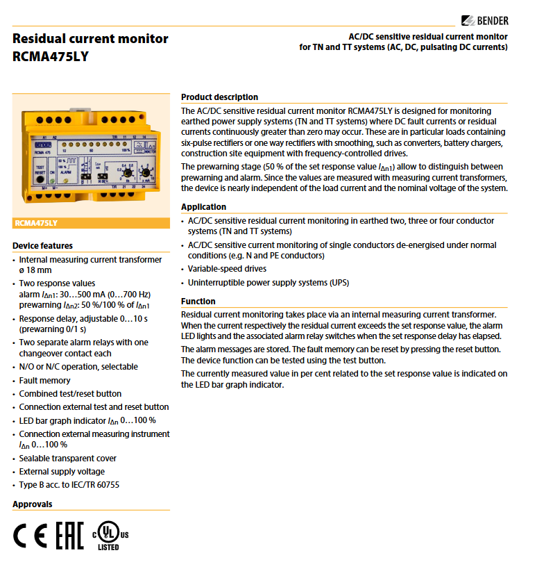
Product Name: RCMA475LY AC/DC Sensitive Residual Current Monitor
Applicable systems: TN system, TT system (grounded power supply system)
Monitoring objects: alternating current (AC), direct current (DC), pulsating DC current
Typical applications: Scenarios with six pulse rectifiers or unidirectional rectification filtering loads, such as frequency converters, uninterruptible power supplies (UPS), battery chargers, construction site variable frequency drive equipment, etc
Core value: Identify continuous DC fault currents or residual currents greater than zero, and prevent electrical safety risks through warning and alarm mechanisms
(2) Compliance and Certification
Following standards: IEC/TR 60755 (Type B), EN 61543, EN 61000-6-4, IEC 60664-1 (Insulation Coordination), etc
Protection level: The shell material meets the UL94V-0 flame retardant standard
Core functions and operational features
(1) Monitoring and threshold setting
Specific parameter adjustability of functional items
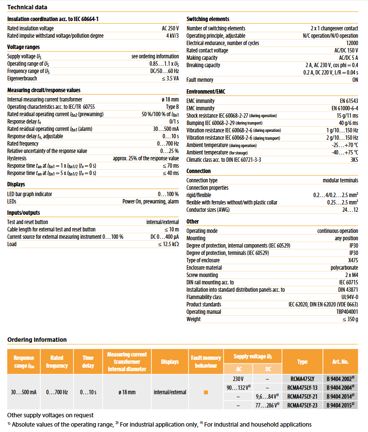
Monitoring frequency range 0... 700Hz fixed
Alarm threshold (I Δ n1) 30... 500mA continuously adjustable
Warning threshold (I Δ n2) 50% I Δ n1 or 100% I Δ n1 DIP switch switching
Alarm response delay 0... 10s potentiometer adjustment (x1/x10 gear)
Warning response delayed by 0s or 1s DIP switch switching
(2) Key functions
Dual independent alarm relay: 2 conversion contacts, supporting NO (normally open)/NC (normally closed) operation mode switching (DIP switch setting), meeting different control circuit requirements.
Fault memory: The alarm status is automatically stored and needs to be manually cleared through the test/reset button for easy fault tracing.
Testing and Reset:
Built in: Combination button (short press<1s=reset, long press>2s=test).
External: Supports connecting external test/reset buttons (cable length is not explicitly limited and needs to be matched with the load).
Display function:
Power On LED: The device is constantly on during operation, but flashes when the measurement range exceeds the limit.
Alarm LED: It lights up when the alarm threshold is reached and flashes when the warning threshold is reached.
LED bar chart: displays the proportion of measured residual current to the set threshold at a scale of 0... 100%.
Detailed technical parameters
(1) Electrical parameters
Category specific specifications
Measurement current transformer built-in, inner diameter ø 18mm (PE conductor must not pass through)
Relative uncertainty of response value ≤ 25%
Lag characteristic ≤ 25% set response value (I Δ n)
Response time (at tv=0s) 1 times I Δ n1: ≤ 70ms; 5 times I Δ n1: ≤ 40ms
Relay parameter contact voltage: 150V AC/DC; Rated current: 5A (AC/DC); Connection capacity: 2A (AC 230V, cos φ=0.4); Breaking capacity: 0.2A (DC 220V, L/R=0.04s)
External measuring instrument interface current source output, 0... 400 µ A (corresponding to 0... 100% I Δ n), load ≤ 12.5k Ω
Supply voltage (by model) RCMA475LY: 230V AC/DC; RCMA475LY-13:90…132V AC/DC; RCMA475LY-21:9.6…84V AC/DC; RCMA475LY-23:77…286V AC/DC
Power consumption ≤ 3.5 VA
(2) Environmental and mechanical parameters
Category specific specifications
Working environment temperature -25...+70 ℃
Storage environment temperature -40...+75 ℃
Climate grade DIN IEC 60721-3-3 (3K5)
Impact resistance performance during operation: 15g/11ms (IEC 60068-2-27); During transportation: 40g/6ms (IEC 60068-2-29)
Vibration resistance performance during operation: 1g/10... 150Hz; During transportation: 2g/10... 150Hz (IEC 60068-2-6)
Installation method: Screw installation (hole diameter 4.3mm)
Shell weight ≤ 350g
The external dimensions refer to DIN 43871/IEC 60715 standard (specific dimensions: 99mm × 91mm × 45mm, subject to the actual product)
(3) Working characteristics of different current types
Current type Operating current range (relative to I Δ n) Remarks
AC current (50Hz) 0.5... 1 × I Δ n sine wave AC
Pulsating DC current (positive and negative half waves) 0.5... 1.4 × I Δ n with half wave rectified current
Phase controlled half wave current (delay angle 90 ° el/135 ° el) 0.5... 1.4 × I Δ n controllable rectifier load
Overlay 6mA smooth DC half wave current 0.5... 1.4 × I Δ n mixed DC+pulsating DC scene
Smooth DC current 0.5... 2 × I Δ n pure DC fault current
Model and ordering information
(1) Model differentiation and order number
Model, Supply Voltage, Applicable Scenarios, Order Number
RCMA475LY 230V AC/DC Industrial+Household B 9404 2002
RCMA475LY-13 90... 132V AC/DC Industrial B 9404 2004
RCMA475LY-21 9.6... 84V AC/DC Industrial B 9404 2014
RCMA475LY-23 77... 286V AC/DC Industrial B 9404 2015
Note: Other power supply voltage versions can be customized according to needs
(2) Recommended supporting components
Component Name Function Model Order Number
External measuring instrument 0... 100% residual current display (size 96 × 96mm) 9604-4241 B 986 807
Measurement converter input 0... 400 µ A, output 0... 10V/4... 20mA RK170 B 9804 1500
Installation and wiring points
The internal diameter of the built-in measuring current transformer is ø 18mm, and PE conductors are strictly prohibited from passing through the transformer to avoid measurement interference.
It is recommended to connect 6A fuses in series in the power supply circuit to ensure the safety of the equipment itself.
The external test/reset button and external measuring instrument need to be connected according to the wiring diagram to ensure stable signal transmission.
The installation location should meet the environmental temperature requirements and be away from heat sources and strong electromagnetic interference sources.
- OMRON
- ABB
- General Electric
- EMERSON
- Honeywell
- HIMA
- ALSTOM
- Rolls-Royce
- MOTOROLA
- Rockwell
- Siemens
- Woodward
- YOKOGAWA
- FOXBORO
- KOLLMORGEN
- MOOG
- KB
- YAMAHA
- BENDER
- TEKTRONIX
- Westinghouse
- AMAT
- AB
- XYCOM
- Yaskawa
- B&R
- Schneider
- KONGSBERG
- NI
- WATLOW
- ProSoft
- SEW
- ADVANCED
- Reliance
- TRICONEX
- METSO
- MAN
- Advantest
- STUDER
- DANAHER MOTION
- Bently
- Galil
- EATON
- MOLEX
- DEIF
- B&W
- ZYGO
- Aerotech
- DANFOSS
- Beijer
- Moxa
- Rexroth
- Johnson
- WAGO
- TOSHIBA
- BMCM
- SMC
- HITACHI
- HIRSCHMANN
- Application field
- XP POWER
- CTI
- TRICON
- STOBER
- Thinklogical
- Horner Automation
- Meggitt
- Fanuc
- Baldor
- SHINKAWA
- Other Brands
- UniOP
- KUKA
- Iba
- Beckhoff
-
 OMRON C60H C6DR DE V1 Sysmac PLC
 -
 MITSUBISHI ELECTRIC A2ACPU21 S1 CPU Module
 -
 ABB BAILEY INNPM12 Network Process Module
 -
 HONEYWELL 620 0073C IPC PLC Module
 -
 Mitsubishi 15050 PR02B PLC Circuit Board
 -
 SIEMENS 6SY7000 0AC37 Drive Control Module
 -
 OMRON TJ2 ECT16 Traxial EtherCAT Controller
 -
 GE Fanuc IC698PSD300D Power Supply Module
 -
 Texas Instruments Series 505 16 Position Base
 -
 OMRON YASKAWA SGDH 10DE OY Servo Drive
 -
 Allen‑Bradley 440G-MT Safety Interlock Switch Specs
 -
 Rubycon PD27A 24V 8A Power Supply Module
 -
 SK-H1-GDB1-F11D PLC Gate Driver Board Kit
 -
 VIPA 441-4UA14 451-4UA14 PLC Module Rack
 -
 Mitsubishi FX5U-80MT ESS PLC Controller Specs
 -
 Mitsubishi Q64TCRTN Temperature PLC Module
 -
 GE 1C31170G Rev10 PLC Circuit Board Module
 -
 Schneider TWDLMDA40DTK PLC Controller Module
 -
 Omron FQM1-MMA22 Motion Control Module Specs
 -
 OMRON CJ1W-NCF71 Position Control Unit Specs
 -
 Schneider TSXETY4103 Ethernet Module
 -
 Mitsubishi Q12PHCPU Process CPU
 -
 Yaskawa 3G3HV-A4022-CE AC Drive
 -
 Cincinnati Milacron 3-533-0669G Temperature Control Board
 -
 Allen Bradley 20AC030A3AYNANC0 PowerFlex 70 Drive
 -
 Siemens 6ES7314-6BG03-0AB0 CPU 314C-2 DP
 -
 Carrier 17EX54007903 PLC Module
 -
 OMRON CS1W-V600C12 ID Controller Module
 -
 Honeywell 51402755-100 PCB Card
 -
 Heidenhain ECN 113 Rotary Encoder
 -
 OMRON B7AM-8B16 I/O Terminal Block
 -
 Fanuc A06B-6110-H026 Power Supply Module
 -
 Schneider TSXETG3021 Ethernet Gateway
 -
 OMRON CS1W-CLK21-V1 Controller Link Unit
 -
 NP1W6406T-Z704 PLC I/O Module
 -
 OMRON CJ1W-DA08C Analog Output Module
 -
 Yaskawa 3G3HV-A4022-CE AC Drive
 -
 OMRON NB7W-TW01B CP1L-EL20DR-D Power Panel
 -
 OMRON C500-NC103-E Position Control Unit
 -
 Steag Hamatech PLC DCS Servo Control System
 -
 Siemens 6SN1123-1AA00-0DA1 Power Supply Module
 -
 GE IC693CHS391H CPU & AD693CMM301A PLC Module
 -
 Siemens 6FC5303-0AF23-1AA1 PLC Control Panel
 -
 Square D CM4000T PowerLogic Circuit Monitor J1 F16
 -
 Siemens 6FX5002-5DG10-1BA0 MOTION-CONNECT 500 Cable
 -
 Schmersal SRB324ST 101195504 Safety Relay 24V
 -
 Mitsubishi 15050-PR02A PLC Circuit Board Module
 -
 OMRON CQM1-AD041 Analog Input PLC Module
 -
 Beckhoff EL5042 EtherCAT PLC Terminal Module
 -
 OMRON C200HW-MC402-E Motion Control Unit
 -
 C36TC0UA1100 Industrial Temperature Controller
 -
 NL8048BC24 12 Industrial Control LCD Module
 -
 OMRON R88D Servo Drive and Motor System
 -
 OMRON CS1W CLK21 V1 Controller Link Module
 -
 OMRON YASKAWA R7M A20030 S1 D Servo Motor
 -
 SIEMENS 6AV2128 3KB06 0AX1 Unified Comfort Panel
 -
 Schneider Electric METSEPM8240 PowerLogic Meter
 -
 Advanced AMCI 1PLC 1 31F Programmable Limit Switch
 -
 ABB PM582 ETH Programmable Logic Processor
 -
 SIEMENS 6FC5110 0CB01 0AA0 CPU Control Board
 -
 Schleicher P03GS13A CPU Module
 -
 Siemens 6SN1123-1AA00-0BA1 Power Module
 -
 Mitsubishi A1S61PN Power Supply Module
 -
 Yaskawa CPS-IONB DC Power Supply Module
 -
 Siemens 6ES7215-2BD00 CPU 215-2
 -
 Mitsubishi A2ACPU MELSEC PLC System Kit
 -
 ProSoft 3150-MCM Communication Module
 -
 Mitsubishi OSE104ET Incremental Encoder
 -
 OMRON CJ1W-AD081-V1 Analog Input Module
 -
 Broadcom BCM5464A1KRB Quad Port Ethernet IC
 -
 Modicon M221-24IO TM221C24 PLC 24 PNP Transistor
 -
 Allen-Bradley 1321-3R160-B Line Reactor 3R160B
 -
 Beckhoff CX1020-0012 Embedded PLC Module Specs
 -
 Turck BL20-PF-24VDC-D Power Feed Module Specs
 -
 Siemens 6SY7000-0AC37 Power Supply Module
 -
 Yaskawa SGDH-10DE-OY 1kW 400V Servo Drive Specs
 -
 Omron 3G3SV-BB015-E 1.5kW 220V VFD Specs
 -
 Uni-Pro CPU91-PLC J 23.020167X Processor Module
 -
 PASABAN MTC-3044 PLC Rack Power Supply 4835-A
 -
 XYCOM 3015T Operator Interface Panel BIN4.4.4
 -
 OMRON CJ1W-MD261 Mixed I/O Module
 -
 Omron NJ301-1100 PLC CPU eCat EIP Specs
 -
 Omron F500-C15-ETN Vision System PLC Module
 -
 Modicon M241-24IO TM/T2UK PLC with Ethernet
 -
 SIXNET YS-800-001 RTU PLC Module
 -
 BEMAC UST-202-D Interface Board 1307D V08B2
 -
 Yaskawa JANCD-MMOIC-02 Drive Circuit Board
 -
 ABB 3BSE005028R1 SDCS-COM-1 Comm Board
 -
 Omron 3G3MX2-A4110 A4150 Inverter Drives Specs
 -
 KEYENCE CA-E100 PLC Module
 -
 GE IC693ALG223-GB Analog Input Module Specs
 -
 ABB BAILEY IMMFP01 Multi Function Processor System
 -
 SIEMENS 6FC5372 0AA00 0AA1 NCU 7202 Controller
 -
Modicon TM241CE4 40I O Transistor Programmable Controller
-
 SIEMENS 6ES7 315 2EH13 0AB0 CPU 3152 PN DP
 -
 NORIS A1 91 PCB Card Rack Module System
 -
 SIEMENS 6ES7 313 5BE01 0AB0 Compact CPU
 -
 SCHNEIDER ELECTRIC S144B MICROLOGIC 60A Trip Unit
 -
 CNI PLC269 v3 Control Module Board Rev H
 -
ABB BAILEY IIMCP02 Processor Module
-
 OMRON NT20S ST121 EV3 Operator Interface Terminal
 -
 OMRON NS-CA001 Video Input Unit
 -
 GE Fanuc IC695CHS012 RX3i Backplane
 -
 Allen Bradley 2711E-K14C6 PanelView 1400e Terminal
 -
 Siemens Sinamics CCB 10000432.71 Power Cell
 -
 Siemens 6SL3210-1SE21-8UA0 Power Module PM340
 -
 Yaskawa CIMR-F7A20P4 AC Drive
 -
 Beckhoff EP1918-0002 EtherCAT Box I/O Module
 -
 OMRON CQM1-TC001 Temperature Control Module
 -
 GE Fanuc SGHA36AT0400 Industrial Contactor
 -
 OMRON NJ501-1500 PLC Machine Automation Controller
 -
 Mitsubishi MAZAK QX084 Power Supply MELDAS 500 CNC
 -
 B&R 0AC808.9 PLC Automation Module
 -
 OMRON CP1H-XA40DT1-D PLC Module
 -
 G&W Electric PLC15 5111 011 15kV Capnut Assembly
 -
 GE DS200SLCCG3AGH PCB Circuit Board
 -
 Siemens SINUMERIK 6FC3981-4FD PLC Extension
 -
 OMRON F300-DC I/O Image Processing Unit
 -
 FANUC A06B-0314-B002 AC Servo Motor
 -
 GC-S84 Programmable Controller Logic Module
 -
 PASABAN MONTELEC MTC3001-DC Drive Control PLC
 -
 Allen Bradley 100E460EJ11 Auxiliary Contactor
 -
 Bosch Rexroth 1070075337-101 Card Parameters
 -
 HMS Anybus AB7646-F Gateway Specifications
 -
 Bosch 062633-303401 CNC Servo PLC Card
 -
 TI 500-5023 Series PLC Power Supply
 -
 Siemens C98043-A7002-L1-12 Circuit Board
 -
 Omron E5CC-RX3A5M-000 Controller


