
RELIANCE ELECTRICI GV3000/SE AC General Purpose (Volts/Hertz) and Vector Duty Drive Version 6.06
GV3000/SE Communication Drive Professional Programming and Startup Guide
Introduction
The GV3000/SE AC drive is a universal frequency converter product launched by the Reliance Electric brand under Rockwell Automation, which supports two adjustment modes: voltage/frequency (V/Hz) and vector control. This article is based on the official technical manual (version 6.06), which systematically outlines its core contents such as hardware characteristics, startup configuration, parameter programming, and fault diagnosis. The aim is to provide engineers and technicians with a complete, professional, and easy-to-use technical reference.
Product Overview and Safety Notice
The GV3000/SE drive is suitable for industrial motor control and has Sensorless Enhanced functionality, supporting open-loop V/Hz and closed-loop vector control. The drive adopts solid-state electronic devices, and its operating characteristics are significantly different from traditional electromechanical devices. Users must read and understand the "Safety Guidelines for Application, Installation, and Maintenance of Solid State Control Devices" (SGI-1.1) before use, and ensure compliance with local safety regulations.
1.1 Important safety signs
Warning: Indicates operations or environments that may cause explosions, personal injury, or equipment damage.
Attention: Identify risks that may cause injury, damage, or economic loss.
SHOCK HAZARD: There may be dangerous voltage inside the equipment.
BURN HAZARD: The surface of the equipment may reach high temperatures.
ARC FLASH HAZARD: May generate an arc, causing serious injury, personal protective equipment (PPE) must be worn.
1.2 Overload protection instructions for electronic motors
This drive does not have speed sensitive overload protection, thermal memory retention, or motor over temperature detection functions. If terminal applications require such protection, it must be implemented through external means.
Initiate the configuration process
The driver supports two adjustment modes: V/Hz (default) and vector control. All hardware installations, including power supply, motor, encoder (optional vector control), and control terminal wiring, must be completed before startup.
2.1 V/Hz control startup process
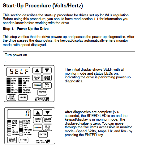
Step 1: Power on and Diagnosis
After the power is turned on, the display shows "SELF", all LEDs light up, and a self-test is performed (about 5-6 seconds). After completion, enter monitoring mode and the speed display will be zero.
Step 2: Enter programming mode
Press the "GRAM" key to enter programming mode and access the first menu's general parameters (P.000-P.006).
Step 3: Set the first menu parameters
P. 000 Control Source: Default is Local Control (LOCL).
P. 001 Acceleration Time 1: Set the time required for the motor to increase from zero speed to maximum speed (1.0-999.9 seconds).
P. 002 Deceleration Time 1: Set the time from maximum speed to zero speed.
P. 003 Minimum speed: Limit the speed reference lower limit (starting from 0.5 Hz).
P. 004 maximum speed: limit the speed reference upper limit (≤ H.022 overclocking limit).
P. 005 current limit: set based on the ratio of motor rated current to driver output current (50-110%).
Step 4: Enter the password for the second menu
Access P.006, enter password "107", unlock the second menu parameters (including V/Hz dedicated parameters H.000-H.022).
Step 5: Configure V/Hz dedicated parameters
H. 001 Motor nameplate fundamental frequency: usually 60 Hz, used to set the V/Hz ratio.
H. 002 Motor nameplate current: must be ≤ the rated current of the motor.
H. 003 Torque boost voltage: compensates for motor voltage drop (0-20%) at low speeds.
H. 017 Input power/braking resistor configuration: Select based on the power type (AC/DC) and whether to use braking resistors.
H. 018 V/Hz curve types: 0=linear (constant torque), 1=optimized curve (Reliance motor), 2=square curve (fan and pump type).
Step 6: Return to monitoring mode and test
Exit programming mode, manually set the speed reference through the keyboard, start the motor, and check the direction of rotation (should be counterclockwise). If the direction is incorrect, it is necessary to cut off the power and switch the wire sequence of any two-phase motor.
Step 7: Full speed operation and monitoring
Gradually increase the speed to the maximum value, and check the output current, voltage, frequency and other parameters through monitoring mode to confirm normal operation.
2.2 Vector control startup process
Vector control is divided into flux vector control with encoder feedback (FVC) and sensor vector control without encoder (SVC).
Step 1: Select Vector Adjustment Mode
In P.048, change the default "U-H" to "UEC", and the driver will be re diagnosed and enter vector control mode.
Step 2: Set basic parameters
Including motor pole number (U.002), nameplate fundamental frequency (U.003), rated current (U.004), rated speed (U.005), etc.
Step 3: Perform Self Tuning
By enabling the self-tuning function through U.008, the driver will automatically run tests to calculate the encoder PPR (FVC) and motor magnetization current (U.006). During the self-tuning period, the motor will run at no load to a certain speed, and it is necessary to ensure that the motor is disconnected from the load.
Step 4: Set the maximum speed of the motor (U.017)
For weak magnetic applications, a value higher than the rated speed can be set; Otherwise, it should be consistent with U.005.
Step 5: Adjust the speed loop parameters
U. 012 Speed loop proportional gain: affects dynamic response, and excessive gain can easily cause oscillation.
U. 013 Speed loop integral gain: usually does not require adjustment, high inertia loads can be adjusted appropriately.
Step 6: Trial operation and direction verification
Similar to the V/Hz process, conduct a low-speed start test to ensure correct steering.
Detailed Explanation of Parameter Programming
3.1 Parameter menu structure
First menu: Common general parameters (P.000-P.006), no password required.
Second menu: Advanced parameters, including:
General parameters (P.007 – P.099)
V/Hz parameters (H.000-H.022)
Vector parameters (U.000-U.048)
RMI board parameters (r.001 – r.066, optional)
Error log (Err)
3.2 Key Parameter Function Description
P. 025 Stop Type: 0=Free Parking, 1=Slope Parking.
P. 040 Motor Overload Enable: Enable electronic thermal overload protection, similar to a thermal relay function.
P. 047 Carrier frequency: selectable from 2, 4, and 8 kHz, affecting motor noise and driver output capability.
P. 054 Level Induction Start Enable: Suitable for remote control, the start signal is level hold rather than edge trigger.
U. 024 High DC Bus Fault Avoidance: After activation, the driver attempts to adjust the bus voltage to avoid faults caused by regenerative energy.
3.3 Programming Security and Password Protection
Keyboard parameter modification can be disabled through P.051, with password "26". P. 006 is used to protect access to the second menu, with a password of "107". The password function only restricts local keyboard modification and does not affect parameter writing through serial port or network.
Monitoring and operation interface
4.1 Keyboard and Display Layout
The keyboard contains 9 keys:
Program: Switch between monitoring/programming mode.
AUTO/MAN: Switch between automatic (external) and manual (local) speed references.
▲/▼: Adjust parameter values or reference speed.
ENTER: Confirm the selection or save of parameters.
START, STOP/RESET, RUN/JOG, FORWARD/REVERSE: Used for local control.
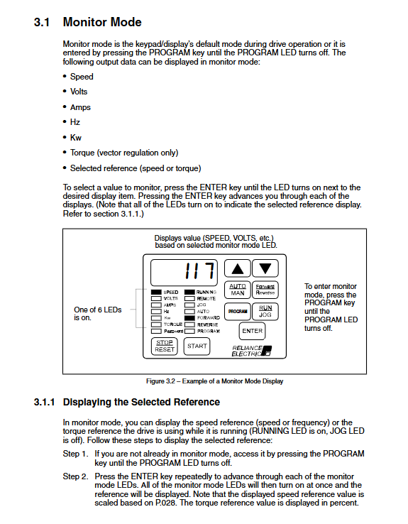
4.2 Monitoring Mode Display Content
Can display the following real-time data in a loop:
Speed (scalable, P.028 setting)
output voltage
output current
output frequency
power (kW)
Torque (specifically for vector control)
4.3 Status indicator lights
RUNNING: The motor is powered on.
Remote: The control source is remote.
AUTO: The speed reference comes from external sources.
FORWARD/REVERSE: Motor direction indicator.
Program: In programming mode.
PASSWORD: Parameter modification is disabled.
Fault diagnosis and error logs
5.1 Alarm and fault codes
Alarm code: Flashing display, driver continues to run (e.g. "LIL" indicates low input voltage).
Fault code: Flashing display, driver shutdown (e.g. "OL" indicates motor overload).
Fatal Fault: Starting with "F", it usually indicates a hardware failure of the regulator board.
5.2 Error log access
By entering the "Err" menu through programming mode, you can view the last 10 fault records, including the occurrence time (based on the 24-hour clock) and date (based on the 248 day counter). The logs can be cleared all at once through the "CLr" option.
5.3 Common Fault Handling
OC/OCA/OCb: overcurrent, check acceleration time, load inertia, and current limit settings.
HU: High DC bus voltage, extending deceleration time or installing braking resistors.
LU: Low DC bus voltage, check the input power supply or adjust the voltage drop time of P.042.
OL: Motor overload, check the rated current parameters of the motor (H.002 or U.004).
SF: Self tuning failed, check the specific reason for U.009.
Advanced features and option configuration
6.1 Network Communication Options
Support network cards such as DeviceNet, ControlNet, PROFIBUS, etc., configure network addresses, reference sources, and response methods through P.060-P.069.
6.2 Outer Loop Control (OCL) Function
Suitable for closed-loop applications such as tension and position, configured with feedback sources, PID parameters, and adjustment ranges through U.040-U.448.
6.3 Braking and Energy Management
Dynamic braking: Configure braking resistors through H.017 to absorb regenerative energy.
DC braking: Set the starting frequency, current, and time of braking through H.005-H.008.
Frequency avoidance: Set the resonance frequency range to be skipped through H.009-H.015.
- OMRON
- ABB
- General Electric
- EMERSON
- Honeywell
- HIMA
- ALSTOM
- Rolls-Royce
- MOTOROLA
- Rockwell
- Siemens
- Woodward
- YOKOGAWA
- FOXBORO
- KOLLMORGEN
- MOOG
- KB
- YAMAHA
- BENDER
- TEKTRONIX
- Westinghouse
- AMAT
- AB
- XYCOM
- Yaskawa
- B&R
- Schneider
- KONGSBERG
- NI
- WATLOW
- ProSoft
- SEW
- ADVANCED
- Reliance
- TRICONEX
- METSO
- MAN
- Advantest
- STUDER
- DANAHER MOTION
- Bently
- Galil
- EATON
- MOLEX
- DEIF
- B&W
- ZYGO
- Aerotech
- DANFOSS
- Beijer
- Moxa
- Rexroth
- Johnson
- WAGO
- TOSHIBA
- BMCM
- SMC
- HITACHI
- HIRSCHMANN
- Application field
- XP POWER
- CTI
- TRICON
- STOBER
- Thinklogical
- Horner Automation
- Meggitt
- Fanuc
- Baldor
- SHINKAWA
- Other Brands
- UniOP
- KUKA
- Iba
- Beckhoff
-
 Basler D90 96801 100 PCB Card
 -
 Basler XR2002F Voltage Regulator (110 VAC, 48-480 Hz)
 -
 Basler SR8A-2B14B3A Regulator
 -
 Basler 9561500100 Module
 -
 Basler DECS-400 BE1-11 System
 -
 Basler DECS-100-B15 Excitation Control
 -
 Basler SCP 210 Frequency Controller
 -
 Basler SR4A-2B15B3A Static Voltage Regulator
 -
 Basler BE1-32R Power Relay
 -
 Basler PIA2400-17GM Power Interface Adapter
 -
 Basler MVC 232 Manual Voltage Control Module
 -
 Basler SSR 32-12 Static Voltage Regulator
 -
 Basler 5MW AVR Generator Voltage Regulator
 -
 Basler VR63-4B Voltage Regulator
 -
 Basler DECS-100-A05 AVR for Engine Generator
 -
 Basler DECS-100-B15 Automatic Voltage Regulator
 -
 Basler BE1-32R Directional Power Relay
 -
 Basler BE1-87B Differential Relay
 -
 Basler UFOV 260A Protective Module
 -
 Basler 9-2614-02-100 PCB Rev M
 -
Basler DECS-100-B15 Digital AVR
-
 Basler 9284900103 PS DECS-400N
 -
 Basler D4N3H1U Intertie Protection
 -
 Basler DECS-100-B15 A15 AVR
 -
 Basler KR4F Voltage Regulator
 -
 Basler BE26434 T14 Transformer
 -
 Basler SR8A-2B15B3A Regulator
 -
 Westinghouse 774B472A12 AR Relay
 -
Basler DECS-100-B15 AVR
-
Basler XR2002F Regulator 110V
-
Basler SR125-E Static Regulator
-
 Basler SSR 125-12 Regulator
 -
 Basler MOC2599 Motor Pot
 -
 Basler BE1-DFPR Feeder Relay
 -
 Basler CBS 305 Current Boost
 -
 Basler BE1-25 AutoSync
 -
 Basler MVC 300 Voltage Control
 -
 Basler BE3-25A AutoSync
 -
 Basler KR7FF Static Regulator
 -
 Basler 90-49000-100 Regulator
 -
 Basler 880 kVA Dry Type Transformer Specs
 -
 Basler Electric BE1-25 Sync-Check Relay Specs
 -
 Basler SSR 125-12 Voltage Regulator Specs
 -
 Basler Electric BE1-851 Overcurrent Relay Review
 -
Basler Electric 149D930G02 Control Sub-Assembly
-
 Basler Electric BE1-81O/UT Frequency Relay Specs
 -
 Basler Electric BE1-51/27C Overcurrent Relay
 -
 Basler Electric 149D956G02 Industrial Component
 -
Basler Electric BE1-51A Overcurrent Relay Specs
-
 Basler Electric BE1-40Q Loss of Excitation Relay
 -
 Basler DECS-200 Excitation Control System
 -
 Basler DECS-200 Voltage Regulator 56-277V AC / 125V DC
 -
Basler BE1-87T Transformer Differential Relay
-
 Basler RDP-110-S1 Protection Relay
 -
 Basler BE1-700V Digital Protective Relay
 -
 Basler BE1-951 Overcurrent Protection System
 -
 Basler DECS-300 Digital Excitation Control
 -
 Basler DECS-200 Digital Excitation Control
 -
 Basler DECS-200-1C Excitation Control System
 -
Basler DECS-200-1L Digital Excitation Control
-
 Basler Electric BE1-GPS Generator Protection System
 -
Basler Electric DECS-200-1C Digital Excitation Controller
-
 Basler Electric DECS125-15 Excitation Control with Power Module
 -
 Basler Electric BE1-87G Differential Relay
 -
 Basler Electric BE1-11 Protection System I5A3M2P2N0EA00
 -
Basler Electric DECS-200-1C Excitation Control System
-
Basler Electric BE1-11g Generator Protection Relay
-
Basler Electric DECS 125-15-B2C1 V2.0.9 Excitation Control
-
 Basler Electric BE1-81O/UT3ED1JA7N2F Frequency Relay
 -
Basler Electric BE1-81O/UT3EE1YB7N1F Frequency Relay
-
 Basler Electric DECS-200-1L Digital Excitation Control System
 -
Basler DECS125-15-B2C1 Excitation Control
-
 Basler 9507900205 SSR Retrofit Voltage Regulator
 -
 Basler BE2000E Digital Voltage Regulator
 -
 Basler BE1-GPS Generator Protection System
 -
Basler DECS-250-CN1CN1N Digital Excitation Control
-
 Basler DGC-2020 Genset Controller
 -
 Basler BE1-81O UT3ED1LA7N0F Frequency Relay (Variant)
 -
 Basler BE1-81O UT3EE1YA9S0F Frequency Relay (Variant)
 -
Basler BE1-81O Over/Under Frequency Relay
-
Basler DECS125-15 Digital Excitation Control
-
Basler Electric BE1-951 Overcurrent Protection System
-
 Basler Electric BE1-700V Digital Protective Relay
 -
 Basler Electric APR63-5 Automatic Voltage Regulator
 -
Basler Electric BE1-851 Overcurrent Protection System
-
Basler Electric DECS-250-LN1SN1N Excitation Control
-
 Basler Electric BE1-87T Transformer Differential Relay
 -
Basler Electric DECS-200-1L Excitation Control System
-
 Basler Electric 9310300100 DECS-300 Excitation Control
 -
 Basler Electric SSE-N 125-4.5KW Shunt Exciter Regulator
 -
 Basler Electric DGC-2020HD-5NS1DNSBA Genset Controller
 -
Basler Electric BE1-81-O/UT3EE1JB7N1F Frequency Relay
-
Basler Electric BE1-81T1EE1WA0N1F Frequency Relay
-
 Basler Electric BE1-25M1EA6PN5R1F Sync-Check Relay
 -
 Basler Electric BE1-GPS Generator Protection System
 -
Basler Electric DECS-250-LN1SN1N Excitation Control Rev V
-
 Basler Electric DECS-250-CN2CN1N Excitation Control
 -
Basler Electric BE1-50/51B-207 Overcurrent Relay
-
Basler Electric DECS-300-C0N0 Excitation Control System
-
Basler Electric DECS-200 Digital Excitation Control System
-
Basler Electric DECS-250-LN1CN1N Excitation Unit
-
Basler Electric DECS-250 LN2SA1D Excitation Unit Specs
-
Basler Electric BE1-87T Transformer Relay Review
-
Basler Electric BE1-11 Protection System
-
Basler Electric BE1-GPS100-E4N1H1N Protection System
-
 Allen-Bradley 442G-MABH-R Safety Module
 -
 Beckhoff CX1030-0111 PLC Assembly Profile
 -
 FANUC IC693CPU364 PLC Module
 -
 Orange Denmark Type 200816 220 PLC Specs
 -
 OMRON C200H-SNT31 Sysmac PLC Module
 -
 Allen Bradley 20AB022A3AYNANC0 PowerFlex 70
 -
 OMRON C200HW-PCU01 Position Control Unit
 -
 ABB AO845A-eA Analog Output Module
 -
 OMRON CJ1M-CPU22 CPU Unit
 -
 Allen Bradley 100-E265ED11 Contactor
 -
 Honeywell 51304511-100 Interface Module
 -
 SOLEXY BXF3S0101N0018 Gateway Module
 -
 OMRON CJ2H-CPU65 CPU Unit
 -
 Automation Direct GS2-45P0 AC Drive
 -
 M68-2000 2-Axis Motion CNC Controller
 -
 OMRON CJ1M-CPU11 V3.0 PLC CPU Unit
 -
 OMRON CJ1W-NC413 4-Axis Positioning Controller
 -
 OMRON 3G2A3-PRO16 Programming Console HMI
 -
 Siemens 3VT8440-2AA04-2GA2 Molded Case Circuit Breaker
 -
 Siemens 3RT5045 Contactor Series
 -
 OMRON C200HS-CPU01-E SYSMAC PLC Controller
 -
 OMRON C500-NC103-E Positioning Control Unit
 -
 OMRON CJ1W-TC001 Temperature Control Unit


