
Siemens SINAMICS S120 AC frequency converter
Single machine drive scenarios, such as centrifuges, presses, extruders, elevators, conveyors, and transportation systems, have high requirements for accuracy, stability, and smooth operation.
Specific driving demand scenarios include drives without feedback to the grid (wire drawing, extrusion), drive groups with high availability requirements (incoming line failures do not cause all shafts to fail), as well as central drives (presses, printing, packaging) and modular machine single axis drives.
SINAMICS S120 AC frequency converter
System Overview
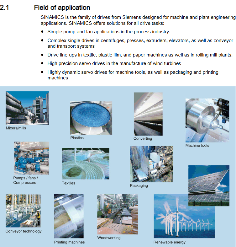
1. Application Fields
SINAMICS, as a Siemens driver product series, covers various industrial applications. The S120 AC frequency converter is specifically suitable for:
Single machine drive scenarios, such as centrifuges, presses, extruders, elevators, conveyors, and transportation systems, have high requirements for accuracy, stability, and smooth operation.
Specific driving demand scenarios include drives without feedback to the grid (wire drawing, extrusion), drive groups with high availability requirements (incoming line failures do not cause all shafts to fail), as well as central drives (presses, printing, packaging) and modular machine single axis drives.
2. Platform concept and integration
Platform concept: All SINAMICS products are based on a unified platform, sharing hardware and software components, using standardized design, configuration, and debugging tools, and can be flexibly combined without system gaps to meet diverse driving tasks.
Fully Integrated Automation (TIA): S120 is one of the core components of TIA, working in collaboration with SIMATIC, SIMOTION, and SINUMERIK. The STARTER debugging tool is an integral part of the TIA platform, supporting parameter setting, programming, and debugging of fully automated systems, and achieving efficient system communication through PROFIBUS DP, PROFINET, and other technologies.
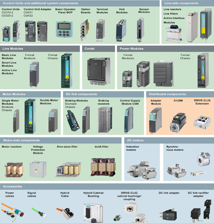
3. System components and data
Core components:
Power components on the grid side, such as fuses, contactors, reactors, and line filters, are used for grid connection and EMC compliance.
Power module (PM): a type that includes or does not include integrated circuit filters and integrated brake choppers, providing power to motors. It comes in series such as PM240-2 and PM340, and is available in formats such as Blocksize and Chassis.
Control Unit (CU) and Adapter: Provides driver and technical functions, such as CU310-2 PN (PROFINET interface), CU310-2 DP (PROFIBUS interface), and adapters such as CUA31 and CUA32 have expandable functions.
Auxiliary system components: such as sensor modules (SMC10/20/30), safety brake relays, safety brake adapters, etc., used for expanding functions and processing encoders, process signal interfaces.
Motor side components: including motor reactors, sine filters, dv/dt filters, etc., to reduce voltage stress on motor windings and lower capacitor charging and discharging currents.
Attachments: such as DRIVE CLiQ cabinet liners, couplers, installation frames, shielding connection kits, etc.
Key system data:
Voltage: Blocksize format supports 1-phase 200-240VAC ± 10%, 3-phase 200-240VAC ± 10%, and 3-phase 380-480VAC ± 10%; Chassis format supports 3-phase 380-480VAC ± 10%; The electronic power supply is 24VDC -15/+20% (PELV or SELV).
Frequency: Rated pulse frequency Blocksize format 4kHz, Chassis format 2kHz, higher than this frequency, current derating should be considered; The line frequency is 47-63Hz.
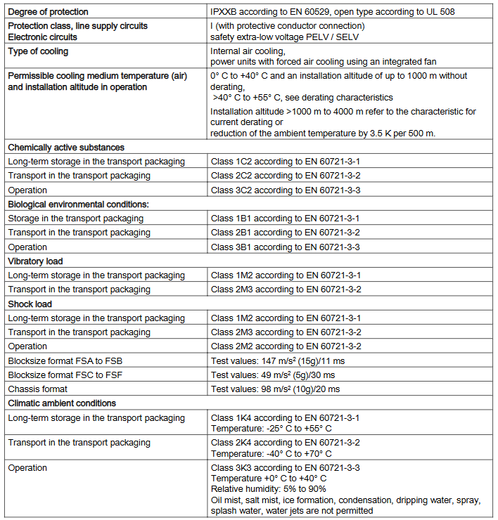
Protection and Environment: Protection level IPXXB (UL 508 open type), Line power supply circuit protection level I (with protective grounding), Working environment temperature 0-40 ℃ (no derating below 1000m), Humidity 5% -90%, No oil mist, salt mist, icing, condensation water, etc.
Core Component Details
1. Power Modules
Classification and Structure:
PM240-2 (Blocksize): Power range 0.55-15kW, including line side diode rectifier, DC link electrolytic capacitor (with pre charging circuit), output inverter, brake chopper, etc. It has built-in and through cooling methods, with and without line filter versions, suitable for different frame sizes (FSA/FSB/FSC), needs to be installed vertically, and maintains a specific ventilation gap (such as 80mm above FSA and 100mm below FSA).
PM340 (Blocksize): Power range 0.12-90kW, similar in structure to PM240-2, with more frame sizes (FSA-FSF), vertically installed, with different ventilation gaps for different frame sizes (such as FSA/FSB up and down 100mm, FSC up and down 125mm, etc.), some can be installed as basic components in combination with line reactors.
Chassis format power module: current range 210-490A, internal air cooling, short circuit/ground fault protection, with electronic nameplate and LED status display, communicating with the control unit through DRIVE CLiQ, paying attention to fan voltage regulation (setting transformer taps according to grid voltage), and removing interference suppression capacitor connection brackets in non grounded grids (IT systems).
Technical parameters: Different models of power modules have different rated currents, power losses, cooling air requirements, and adapted motor powers. For example, the PM240-2 FSA (200V) has a rated current of 3.9A and a power loss of 0.04kW; the Chassis format 1TE32-1AA3 model has a rated current of 210A and a power loss of 2.46kW, and attention should be paid to overload capacity (such as short-term overload current, overload duration) and derating characteristics (affected by environmental temperature, pulse frequency, and installation height).
2. Control unit and adapter
Control unit (CU310-2 series):
CU310-2 PN: PROFINET interface, including 11 isolated digital inputs, 8 non isolated digital inputs/outputs, 1 isolated digital output and other interfaces, supports HTL/TTL/SSI encoder evaluation, analog setpoint input, hot swappable, firmware version 4.4 and above available, LED display status (RDY, COM, etc.), switches analog input types through DIP switch S5, has a RESET button to restart the device and backup data.
CU310-2 DP: PROFIBUS interface, interface type similar to CU310-2 PN, PROFIBUS address set through two rotary encoding switches (0-127dec), supports synchronous operation, can connect to remote diagnostic teleservice adapter, and other functions (such as LED status, reset, analog input switching) are similar to CU310-2 PN.
Control Unit Adapter (CUA Series):
CUA31: Used to connect the power module as an additional axis to the existing DC/AC group, requiring a higher-level closed-loop control module with DRIVE CLiQ interface, EP terminal/temperature sensor interface, etc., and LED display status.
CUA32: Similar in function to CUA31, with additional support for evaluating HTL/TTL/SSI encoders, and corresponding addition of encoder interfaces for interface configuration. Other features (such as power supply and connection method) are similar to CUA31.
3. DC link components
Braking resistor (Blocksize): Used for energy conversion during regenerative operation of PM240-2 and PM340 power modules (such as braking rotating mass), with a constant temperature switch to monitor overheating. The resistance value, rated power, and size of the braking resistor vary depending on the frame size (such as FSA-FSF), and attention should be paid to installation clearance (such as 100mm on each side of PM340 braking resistor) and protection (to avoid contact burns and fire prevention).
Braking module and resistor (Chassis): The braking module is installed in the power module slot, with forced air cooling, including power electronics and control, requiring an external braking resistor. The interface includes DC link connection, braking resistor connection, digital input/output, etc. The braking resistor (25kW/50kW) is installed outside the cabinet, with temperature protection switch, and needs to be installed vertically and independently, maintaining a 200mm cooling gap to avoid water intrusion (IP20 protection, outdoor canopy required).
4. Power components on the motor side
Motor reactors: available in Blocksize and Chassis formats to reduce voltage stress on motor windings, lower capacitor charging and discharging currents, and adapt to different power modules. For example, Blocksize format is compatible with PM240-2 and PM340, while Chassis format is compatible with Chassis power modules. Technical parameters include inductance, rated current, power loss, etc. Attention should be paid to installation (near the power module, maximum 5m connecting cable), ventilation gap (around 100mm), and frequency limitation (maximum 150Hz output frequency, 4kHz pulse frequency).
Sinusoidal filter (Chassis): enables the power module to output a voltage close to sine, can use unshielded cables, does not require derating of motor power, adapts to Chassis power module, pulse frequency needs to be set to 4kHz (causing derating of power module output current), output voltage needs to be reduced by 15%, avoid no motor operation (damaging the filter), install and maintain a ventilation gap of 100mm, pay attention to the connection direction (input to power module, output to motor).
Dv/dt filter: includes dv/dt reactor and voltage peak limiter, which limits the voltage rise rate (such as<500V/μ s) and voltage peak value. It is used in scenarios where the voltage resistance of the motor insulation system is unknown or insufficient. It is divided into ordinary and compact types, and attention should be paid to grounding protection (to avoid high discharge current risks), installation clearance, frequency limitation (maximum 150Hz output, 4kHz pulse frequency), and cannot operate without a motor.
Installation and debugging related
1. Grid connection and line components
Connection component selection: Line circuit breakers, overcurrent protection (line fuses, circuit breakers), line contactors (electrical isolation), line filters (EMC compliance), line reactors (limiting low-frequency line harmonics) are required to adapt to different voltages (such as 1-phase 200-240V, 3-phase 380-480V) and power grid systems (TN, TT, IT systems, IT systems require motor reactors).
Installation and safety: Attention should be paid to the installation direction of line filters and reactors (correct connection of input and output terminals), ventilation gap (such as 100mm above and below the line filter), grounding (protective grounding in accordance with specifications), and overvoltage protection. It is recommended to install surge arresters (such as VZCA/VZCA2) at the incoming terminal. Residual current equipment (RCD/RCM) should be selected according to system requirements (such as TT system, RCM required for high-power incoming lines).
2. Cabinet design and EMC
Cabinet manufacturing safety: Follow safety instructions to ensure cabinet protection (such as IP54 to avoid conductive contamination), reasonable component layout (considering heat dissipation and electromagnetic interference), 24V DC power supply needs overcurrent and overvoltage protection, and select appropriate power units (based on component current consumption).
EMC compliance: Cable shielding and wiring must comply with specifications (such as DRIVE CLiQ signal cable selection and shielding connection), component grounding (protective grounding, equipotential connection), and follow the EMC installation guidelines (Configuration Manual 6FC5297-0AD30-0xPx). Different EMC categories (C1/C2/C3/C4) correspond to different application environments (such as C1 for public systems and C3 for industrial systems), and corresponding measures (such as line filters and reactors) must be taken to meet the limits.
3. Debugging and Tools
Debugging Tools: Use the STARTER debugging tool in conjunction with the SIZER configuration tool for driver selection and configuration. Document support includes SIZER and configuration manuals during the planning/engineering phase, STARTER, beginner's guides, debugging manuals during the debugging phase, and operation manuals and list manuals during the usage phase.
Debugging process: It is necessary to follow safety steps (such as power-off, discharge, and power verification), configure parameters (such as motor parameters and control modes), test functions (such as safety functions and braking functions), check EMC compliance, and ensure that all components (such as power modules, control units, and filters) are connected correctly and functioning properly.
Service and Maintenance
1. Safety maintenance requirements
Before maintenance, it is necessary to ensure that the equipment is powered off, wait for the DC link capacitor to discharge (up to 5 minutes), verify that there is no voltage, identify and isolate all hazardous energy sources (such as compressed air and hydraulic systems), ensure that the protective conductor connections are compliant (to avoid high discharge current risks), and only allow qualified personnel to operate.
Regularly check the tightening torque of power connections (such as lines, motors, DC link connections), pay attention to the status of vulnerable parts (such as fans, capacitors), and follow environmental requirements (temperature, humidity, no pollutants).
2. Component replacement and maintenance
Hardware replacement: such as control unit fan (CU310-2 DP/PN), power module fan (PM240-2, PM340, Chassis format), power module power block (Chassis format FX/GX), control interface module (Chassis format), etc., specific steps need to be followed (such as removing cover plate, disconnecting, installing new components, restoring cover plate), paying attention to tightening torque and wiring correctness.
Capacitor formation: DC link capacitors need to be formed regularly (such as after long-term storage), following the manual process (such as gradually applying voltage and monitoring current) to ensure capacitor performance.
- OMRON
- ABB
- General Electric
- EMERSON
- Honeywell
- HIMA
- ALSTOM
- Rolls-Royce
- MOTOROLA
- Rockwell
- Siemens
- Woodward
- YOKOGAWA
- FOXBORO
- KOLLMORGEN
- MOOG
- KB
- YAMAHA
- BENDER
- TEKTRONIX
- Westinghouse
- AMAT
- AB
- XYCOM
- Yaskawa
- B&R
- Schneider
- KONGSBERG
- NI
- WATLOW
- ProSoft
- SEW
- ADVANCED
- Reliance
- TRICONEX
- METSO
- MAN
- Advantest
- STUDER
- DANAHER MOTION
- Bently
- Galil
- EATON
- MOLEX
- DEIF
- B&W
- ZYGO
- Aerotech
- DANFOSS
- Beijer
- Moxa
- Rexroth
- Johnson
- WAGO
- TOSHIBA
- BMCM
- SMC
- HITACHI
- HIRSCHMANN
- Application field
- XP POWER
- CTI
- TRICON
- STOBER
- Thinklogical
- Horner Automation
- Meggitt
- Fanuc
- Baldor
- SHINKAWA
- Other Brands
- UniOP
- KUKA
- Iba
- Beckhoff
-
 OMRON B7AM-8B16 I/O Terminal Block
 -
 Fanuc A06B-6110-H026 Power Supply Module
 -
 Schneider TSXETG3021 Ethernet Gateway
 -
 OMRON CS1W-CLK21-V1 Controller Link Unit
 -
 NP1W6406T-Z704 PLC I/O Module
 -
 OMRON CJ1W-DA08C Analog Output Module
 -
 Yaskawa 3G3HV-A4022-CE AC Drive
 -
 OMRON NB7W-TW01B CP1L-EL20DR-D Power Panel
 -
 OMRON C500-NC103-E Position Control Unit
 -
 Steag Hamatech PLC DCS Servo Control System
 -
 Siemens 6SN1123-1AA00-0DA1 Power Supply Module
 -
 GE IC693CHS391H CPU & AD693CMM301A PLC Module
 -
 Siemens 6FC5303-0AF23-1AA1 PLC Control Panel
 -
 Square D CM4000T PowerLogic Circuit Monitor J1 F16
 -
 Siemens 6FX5002-5DG10-1BA0 MOTION-CONNECT 500 Cable
 -
 Schmersal SRB324ST 101195504 Safety Relay 24V
 -
 Mitsubishi 15050-PR02A PLC Circuit Board Module
 -
 OMRON CQM1-AD041 Analog Input PLC Module
 -
 Beckhoff EL5042 EtherCAT PLC Terminal Module
 -
 OMRON C200HW-MC402-E Motion Control Unit
 -
 C36TC0UA1100 Industrial Temperature Controller
 -
 NL8048BC24 12 Industrial Control LCD Module
 -
 OMRON R88D Servo Drive and Motor System
 -
 OMRON CS1W CLK21 V1 Controller Link Module
 -
 OMRON YASKAWA R7M A20030 S1 D Servo Motor
 -
 SIEMENS 6AV2128 3KB06 0AX1 Unified Comfort Panel
 -
 Schneider Electric METSEPM8240 PowerLogic Meter
 -
 Advanced AMCI 1PLC 1 31F Programmable Limit Switch
 -
 ABB PM582 ETH Programmable Logic Processor
 -
 SIEMENS 6FC5110 0CB01 0AA0 CPU Control Board
 -
 Schleicher P03GS13A CPU Module
 -
 Siemens 6SN1123-1AA00-0BA1 Power Module
 -
 Mitsubishi A1S61PN Power Supply Module
 -
 Yaskawa CPS-IONB DC Power Supply Module
 -
 Siemens 6ES7215-2BD00 CPU 215-2
 -
 Mitsubishi A2ACPU MELSEC PLC System Kit
 -
 ProSoft 3150-MCM Communication Module
 -
 Mitsubishi OSE104ET Incremental Encoder
 -
 OMRON CJ1W-AD081-V1 Analog Input Module
 -
 Broadcom BCM5464A1KRB Quad Port Ethernet IC
 -
 Modicon M221-24IO TM221C24 PLC 24 PNP Transistor
 -
 Allen-Bradley 1321-3R160-B Line Reactor 3R160B
 -
 Beckhoff CX1020-0012 Embedded PLC Module Specs
 -
 Turck BL20-PF-24VDC-D Power Feed Module Specs
 -
 Siemens 6SY7000-0AC37 Power Supply Module
 -
 Yaskawa SGDH-10DE-OY 1kW 400V Servo Drive Specs
 -
 Omron 3G3SV-BB015-E 1.5kW 220V VFD Specs
 -
 Uni-Pro CPU91-PLC J 23.020167X Processor Module
 -
 PASABAN MTC-3044 PLC Rack Power Supply 4835-A
 -
 XYCOM 3015T Operator Interface Panel BIN4.4.4
 -
 OMRON CJ1W-MD261 Mixed I/O Module
 -
 Omron NJ301-1100 PLC CPU eCat EIP Specs
 -
 Omron F500-C15-ETN Vision System PLC Module
 -
 Modicon M241-24IO TM/T2UK PLC with Ethernet
 -
 SIXNET YS-800-001 RTU PLC Module
 -
 BEMAC UST-202-D Interface Board 1307D V08B2
 -
 Yaskawa JANCD-MMOIC-02 Drive Circuit Board
 -
 ABB 3BSE005028R1 SDCS-COM-1 Comm Board
 -
 Omron 3G3MX2-A4110 A4150 Inverter Drives Specs
 -
 KEYENCE CA-E100 PLC Module
 -
 GE IC693ALG223-GB Analog Input Module Specs
 -
 ABB BAILEY IMMFP01 Multi Function Processor System
 -
 SIEMENS 6FC5372 0AA00 0AA1 NCU 7202 Controller
 -
Modicon TM241CE4 40I O Transistor Programmable Controller
-
 SIEMENS 6ES7 315 2EH13 0AB0 CPU 3152 PN DP
 -
 NORIS A1 91 PCB Card Rack Module System
 -
 SIEMENS 6ES7 313 5BE01 0AB0 Compact CPU
 -
 SCHNEIDER ELECTRIC S144B MICROLOGIC 60A Trip Unit
 -
 CNI PLC269 v3 Control Module Board Rev H
 -
ABB BAILEY IIMCP02 Processor Module
-
 OMRON NT20S ST121 EV3 Operator Interface Terminal
 -
 OMRON NS-CA001 Video Input Unit
 -
 GE Fanuc IC695CHS012 RX3i Backplane
 -
 Allen Bradley 2711E-K14C6 PanelView 1400e Terminal
 -
 Siemens Sinamics CCB 10000432.71 Power Cell
 -
 Siemens 6SL3210-1SE21-8UA0 Power Module PM340
 -
 Yaskawa CIMR-F7A20P4 AC Drive
 -
 Beckhoff EP1918-0002 EtherCAT Box I/O Module
 -
 OMRON CQM1-TC001 Temperature Control Module
 -
 GE Fanuc SGHA36AT0400 Industrial Contactor
 -
 OMRON NJ501-1500 PLC Machine Automation Controller
 -
 Mitsubishi MAZAK QX084 Power Supply MELDAS 500 CNC
 -
 B&R 0AC808.9 PLC Automation Module
 -
 OMRON CP1H-XA40DT1-D PLC Module
 -
 G&W Electric PLC15 5111 011 15kV Capnut Assembly
 -
 GE DS200SLCCG3AGH PCB Circuit Board
 -
 Siemens SINUMERIK 6FC3981-4FD PLC Extension
 -
 OMRON F300-DC I/O Image Processing Unit
 -
 FANUC A06B-0314-B002 AC Servo Motor
 -
 GC-S84 Programmable Controller Logic Module
 -
 PASABAN MONTELEC MTC3001-DC Drive Control PLC
 -
 Allen Bradley 100E460EJ11 Auxiliary Contactor
 -
 Bosch Rexroth 1070075337-101 Card Parameters
 -
 HMS Anybus AB7646-F Gateway Specifications
 -
 Bosch 062633-303401 CNC Servo PLC Card
 -
 TI 500-5023 Series PLC Power Supply
 -
 Siemens C98043-A7002-L1-12 Circuit Board
 -
 Omron E5CC-RX3A5M-000 Controller
 -
 CN-8032-L Profinet Network Adapter Module
 -
 Siemens 3TK2804-0BB4 Safety Relay Details
 -
 Toledo TTLM-2-1M I/O Load Module
 -
 NORIS A1-91 PLC Rack Board Specifications
 -
 Mitsubishi A3ACPUR21 MELSEC PLC CPU Module
 -
 Beckhoff EP7041‑3002 EtherCAT Box Digital Input Module
 -
 REER EOS2E 1053 EOS2R 1053 Safety Light Curtain
 -
 Mitsubishi Q80BD-J71BR11 MELSECNET/H Interface Board
 -
 Omron 3G3IV-B4220-EV2 VFD 400V 22kW
 -
 Allen-Bradley 96844671 1785-LT3 PLC-5/12 Processor Module
 -
 Pasaban MTC3001-DC Drive Control PLC Module
 -
 Omron CJ1M-CPU11 V4.0 PLC CPU Module
 -
 ABB CM579-PNIO B3 Communication Module
 -
 B&R X20 AI 4221 Analog Module
 -
 Siemens 6SY7000-0AC80 PLC Module
 -
 GE 531X300CCHAFM5 Control Card
 -
 AB 810-A15C Inverse Time Relay
 -
 WITTENSTEIN LP120X-MF2-20 Planetary Gear
 -
 Mitsubishi Kakoki E-01B-4130 PLC I/O Modules
 -
 ABB DSQC643 Safety Control Board
 -
 Siemens G26004-A2105-P100-2 PCB
 -
 OMRON F350-C10E Image Processing Unit
 -
 FUJI UG430H-TS1 HMI Touch Panel
 -
 Westronics CB100188-01 Rev F Board
 -
 Siemens 7MH4900-3AA01 Weighing Module
 -
 Gilbert & Nash Tracker 2000 Control Cabinet
 -
 OMRON CJ1M-CPU22 CPU Unit
 -
 OMRON F3SJ-E0625P25 Light Curtain
 -
 Siemens 3VA2340-5HL32-0AA0 Breaker
 -
 Mitsubishi Melsec A61P A2NCPU PLC System


