
Kollmorgen S700 series digital servo amplifier
Kollmorgen S700 series digital servo amplifier
Basic Information
Core positioning: The S700 series is a high-performance digital servo amplifier that supports 208-480VAC three-phase input (S7xx0 model) or 110-230VAC single/three-phase input (S7xx6 model), integrates CANopen and EtherCAT bus interfaces, and comes standard with dual channel STO (Safe Torque Off) function (up to SIL CL3/PLe level). Additional functions such as PROFIBUS, SERCOS, DeviceNet can be achieved through expansion cards. It is recommended to use it with Kollmorgen motors and direct connection to loads is prohibited for operation.
Version and hardware adaptation: The document corresponds to hardware version 02.20 and requires firmware version ≥ 5.18 (ND1/NDO data structure). The functional differences between different hardware versions mainly lie in DC bus parallel capability and memory compatibility (support for memory cards at 02.10 and above). For older versions (such as 00.20/01.21), reference should be made to the corresponding manual revision.
Core technical characteristics and classification of amplifiers
(1) General Technical Parameters
Category parameter item specification
Power characteristic input voltage S7xx0:3 × 208V-10%~3 × 480V+10% (50/60Hz); S7xx6:1×110V-10%~3×230V+10%(50/60Hz)
The maximum DC bus voltage is 900VDC (S7xx0) and 455VDC (S7xx6), with an undervoltage fault of 100VDC and an overvoltage fault of 900VDC (S7xx0)/455VDC (S7xx6)
Rated output current of 1.5-24ARMS (e.g. S70102 is 1.5ARMS, S72402 is 24ARMS), peak value of 4.5-72ARMS (lasting for 2 seconds)
Motor adaptation motor types: synchronous servo motor, asynchronous motor, DC motor, linear motor
Motor inductance range S7xx0 (320VDC bus): 50-200mH; S7xx6 (160VDC bus): 7-30mH
Feedback supports rotary transformers, SinCos encoders (EnDat 2.1/2.2, BiSS-C, HIPERFACE), incremental encoders (ROD), SSI encoders
Control characteristic switch frequency 8kHz (output stage)
Control cycle current loop 62.5 μ s, speed loop 62.5 μ s, position loop 250 μ s (optional 125 μ s)
Safety function dual channel STO (SIL CL3/PLe), supporting extended safety functions such as SS1/SS2/SOS/SLS (requires safety expansion card)
Environmental adaptability: Operating temperature range of 0-40 ℃ (rated working condition), with a reduction of 2.5%/℃ required for 40-55 ℃
Storage temperature -25-70 ℃
Humidity 95% relative humidity (no condensation)
Altitude ≤ 1000m (no downgrading), downgrading 1.5%/100m for 1000-2500m
Protection level IP20 (IEC 60529)
(2) Model classification and key parameters
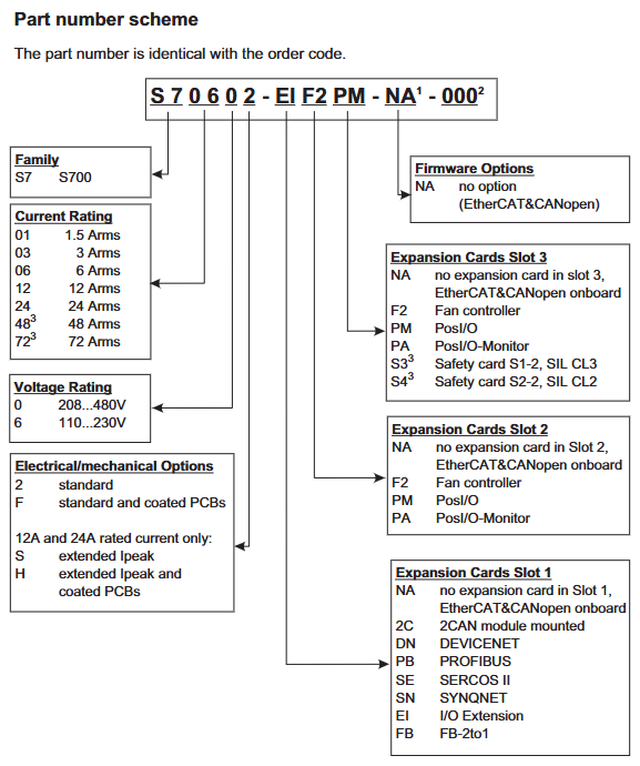
The S700 series is divided into two sub series based on rated output current and input voltage, with the following differences in core parameters:
Subseries models rated output current (ARMS) peak output current (ARMS/2s) input voltage DC bus voltage (VDC) weight (kg) heat dissipation method
S7xx0 (three-phase input) S70102 1.5 4.5 3 × 208-480VAC 900 4.4 Forced air cooling
S70302 3 9 3 × 208-480VAC 900 4.4 forced air cooling
S70602 6 18 3 × 208-480VAC 900 4.4 forced air cooling
S71202/S7120S 12 24/30 3 × 208-480VAC 900 5.5 forced air cooling
S72402/S7240S 24 48/72 3 × 208-480VAC 900 5.5 forced air cooling
S7xx6 (single/three-phase input) S70162 1.5 4.5 1 × 110-230VAC/3 × 110-230VAC 455 4.4 Forced air cooling
S70362 3 9 1 × 110-230VAC/3 × 110-230VAC 455 4.4 Forced air cooling
S70662 6 18 1 × 110-230VAC/3 × 110-230VAC 455 4.4 Forced air cooling
S71262/S7126S 12 24/30 1 × 110-230VAC/3 × 110-230VAC 455 5.5 forced air cooling
S72462/S7246S 24 48/72 1 × 110-230VAC/3 × 110-230VAC 455 5.5 forced air cooling
(3) Optional configurations and expansion cards
Core Function Expansion
Security Expansion Card: Slot 3 can be installed with S3 (S1-2, SIL CL3/PLe) or S4 (S2-2, SIL CL2/PLd) security cards, supporting security functions such as SS1/SS2/SOS/SLS/SPLP. The S3 card also supports safety brake control (SBC) and brake testing (SBT).
Communication expansion card: Slot 1 supports PROFIBUS(DE-106712)、SERCOS(DE-90879)、DeviceNet(DE-103571)、SynqNet(DE-200073),Slot 2/3 Supports PosI/O (DE-200881) to expand high-precision I/O interfaces.
Feedback extension card: FB-2to1 (DE-201664) supports simultaneous connection of digital primary feedback and analog secondary feedback, solving compatibility issues with multiple feedback devices.
Heat dissipation optimization: Option F2 (Slot 2/3) is a controllable fan that automatically adjusts the speed based on temperature (55-75 ℃) and braking power (20-45W) to reduce noise (default fan noise is 43-65dB (A)).
Storage and Communication: Supports MMC/SD memory cards (DE-201257), which can store firmware and parameters, enabling fast configuration of multi axis systems; Standard RS232 (X6), CANopen (X6), EtherCAT (X7) interfaces, EtherCAT supports CAN over EtherCAT protocol and automatically detects bus type.
Installation and wiring specifications
(1) Mechanical installation requirements
Installation preparation
Installation surface: It should be made of conductive material (such as galvanized steel plate) with a flatness error of ≤ 0.1mm. It should be fixed with M5 hexagon socket screws (torque 0.7-0.8Nm). The installation size of S701-S712 is 345 × 70 × 243mm (H × W × D), and S724 is 348 × 100 × 243mm. A heat dissipation space of ≥ 25.4mm should be reserved around it. It is prohibited to install it under a heat source (such as a frequency converter).
Temperature control: If the ambient temperature exceeds 40 ℃, forced air cooling (wind speed ≥ 2m/s) should be added. When the temperature of the heat sink exceeds 80 ℃, the amplifier will overheat and shut down (fault F01). It is recommended to use the S724 model with a cold plate (heat dissipation area ≥ 0.1m ²).
Fan installation
S701-S712 fan: Pinch the long side of the fan housing and pull it down. When installing, align it with the green connector and push it into the buckle lock.
S724 fan: Pinch the short side of the fan housing and pull it down. When installing, make sure the connector is aligned with the socket and press it until the buckle is fixed. The fan has no independent wiring and can be powered through the internal connector.
(2) Electrical wiring specifications
Wiring safety and sequence
Power off operation, ensure capacitor discharge (≥ 8 minutes after power off, measure DC bus voltage<60V), all power cables (motor/power) and control cables (feedback/I/O) need to be separately shielded, and the shielding layer should be grounded 360 ° through the amplifier front panel or metal connector (low impedance).
The distance between power cables and control cables should be ≥ 200mm to avoid cross interference; When the length of the motor cable exceeds 25m, Kollmorgen 3YL/3YLN motor choke coils should be connected in series (such as S70102 with 4 × 1mm ² cable) to reduce leakage current and EMI interference.
Core interface definition
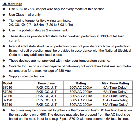
Power interface (X0): S7xx0 model L1/L2/L3 connected to three-phase live wire, PE connected to protective ground; S7xx6 single-phase connection L1/N, three-phase connection L1/L2/L3, PE wire section ≥ 10mm ² or dual PE wiring, external slow melting fuse needs to be configured (such as S70102 with 6A/600V, S72402 with 30A/600V).
Motor interface (X9): U2/V2/W2 is connected to the three-phase winding of the motor, PE is connected to the motor casing, BRAKE+/BRAKE - is connected to a 24V brake (only with a brake motor), the brake current is ≤ 2A, and a separate freewheeling component (such as a varistor) needs to be configured.
Safety interface (X4A/X4B): STO1 Enable (X4B/6) and STO2 Enable (X4A/3) are connected to external safety circuits (24V/33-40mA). In dual channel configuration, safety relay outputs need to be connected separately to ensure SIL CL3 level. When not in use, they need to be short circuited to+24V.
Feedback interface (X1/X2): X2 is the rotary transformer interface (9-pin SubD), R1/R2 is the reference signal, S1/S2/S3/S4 is the sine/cosine signal; X1 is an encoder interface (15 pin SubD) that supports protocols such as EnDat/BiSS/HIPERFACE. The FBTYPE parameter needs to be selected based on the feedback type (e.g. EnDat 2.2 is set to 32/34).
Typical wiring scheme
Three phase power supply (S70602): L1/L2/L3 connected to 3 × 400VAC, PE connected to cabinet ground, X0 terminal tightened with a torque of 0.7-0.8Nm, power supply side connected in series with 10A slow melting fuse (UL class RK5) to avoid damage from surge current.
Motor and brake (with brake motor): X9 terminal U2/V2/W2 is connected to the motor winding, BRAKE+is connected to 24V power supply, BRAKE - is connected to amplifier X9/1, the brake control wire uses shielded twisted pair (such as 2 × 0.75mm ²), the shielding layer is grounded at both ends, and additional mechanical braking is required for vertical axis applications (brake is only used for parking and frequent braking is prohibited).
STO safety circuit (dual channel): STO1 Enable (X4B/6) is connected to the normally closed contact of safety relay K1, STO2 Enable (X4A/3) is connected to the normally closed contact of safety relay K2, and the relay coil is controlled by the emergency stop button. When the emergency stop is triggered, the STO signal is disconnected, and the amplifier cuts off the motor torque (fault F27).
Security Features and System Configuration
(1) STO security function (core security feature)
Function definition and level
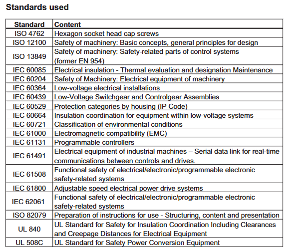
STO (Safe Torque Off) achieves no torque output of the motor by blocking the triggering pulse of the power transistor, which complies with EN 60204-1 stop category 0 (uncontrolled shutdown). The single channel configuration (STO1/STO2 series) reaches SIL CL2/PLd, and the dual channel+cycle test (safety controller monitoring feedback signal) reaches SIL CL3/PLe. The PFH_D is 1.04E-09 1/h, and the MTBF is 20 years.
Wiring and Testing
Single channel wiring: STO1 Enable and STO2 Enable are connected in series and then connected to a safety relay output. The reference ground is XGND (X4B/5), with an input voltage of 20-30VDC and a current of 33-40mA. When disconnected, the amplifier displays "- S -" and the motor has no torque.
Functional testing:
When the motor is stationary (the enable signal is valid), disconnect the STO input, the amplifier should immediately cut off the torque, display fault F27, and the BTB/RTO contact (X3B/14-15) is disconnected.
Reset STO input, use Fault Reset input (X3A/18) or software reset to restore the amplifier to normal state, with a test cycle of ≤ 8 hours (SIL CL3 requirement).
(2) System configuration (software and hardware settings)
Software Configuration (DRIVE GUI. EXE)
Installation and Connection: Supports Windows 2000/XP/Vista/7, connects PC and amplifier X6 interface through RS232 cable (P7S2-232-9D), baud rate 38400bps, data bit 8, even check, stop bit 1, software automatically recognizes amplifier model and firmware version.
Core configuration module:
Motor configuration: Select the motor model (such as AKM series) from the database, or manually input parameters such as rated current, torque constant, inductance, etc., and perform the "Motor Probe" to detect the motor inductance and optimize the current loop gain.
Security configuration: The STO function requires setting the STO Status output (such as X3A/6) and associating it with the security controller through the ASCII command OxMODE70 to achieve periodic testing; The security card S3/S4 needs to be configured with SS1 activation signal (X30/1) and reset signal (X30/20) to ensure the correct triggering timing of the security function.
Sports configuration: Set the electronic gear ratio for the position ring (e.g. set PGEAR1=2 and PGEAR0=1 for a 1:2 gearbox), gain for the speed ring (Kp=0.5-2.0, Tn=0.01-0.1s), and automatically optimize control parameters through "Autotuning" to reduce tracking errors (fault F03).
Hardware switch configuration
Address and baud rate: Set the CANopen station address (1-99) and baud rate (10-1000kbit/s) through the amplifier front-end buttons. After setting, restart the 24V power supply to take effect. The baud rate encoding is as follows: "25" corresponds to 250kbit/s, and "50" corresponds to 500kbit/s.
Expansion card recognition: After inserting the expansion card into Slot 1/2/3, the amplifier will automatically recognize it when powered on. The function can be configured through the DRIVE GUI "Expansion Card" interface (such as setting the PROFIBUS address to 3 and the baud rate to 1.5Mbit/s). If the expansion card is not recognized, it is necessary to check whether it is installed properly (card buckle locking).
Troubleshooting and Maintenance
1、 Troubleshooting System
(1) Fault diagnosis tools and processes
Front end LED display diagnosis
The 3-character LED display on the front end of the amplifier is the core fault indicator unit, and different states correspond to different fault types:
Red flashing: Fault code (such as F01-F32), it is necessary to locate the problem based on the fault table, and the number of flashes corresponds to the fault number (such as flashing once is F01).
Yellow constantly on: EOT (end of travel) input latch (such as n10/n11), the motor needs to be moved in reverse to disengage from the limit sensor.
Red constantly on: FLASH memory verification error (F09), firmware needs to be re downloaded (via memory card or PC software).
- S - "display: STO function activated (STO1/STO2 Enable is 0V), check the safety circuit wiring or safety relay status.
Troubleshooting process
Preliminary inspection: Confirm if the power supply voltage (X0 terminal), 24V auxiliary power supply (X4A), and STO signal (X4A/3/X4B/6) are normal, disconnect the load to test the motor for independent operation, and eliminate mechanical jamming.
Parameter verification: Read parameters (such as motor current, speed, and bus voltage) through DRIVE GUI software, confirm that I2/rms/I2 peak does not exceed the rated value, and provide feedback parameters (FBTYPE, ENCVON) that match the actual feedback type.
Hardware testing: Measure the resistance of the motor winding (three-phase balance, deviation ≤ 5%), feedback cable continuity (if there is no open circuit between terminal X1 A+/A -), and check the temperature of the power module (triggering F01 when the heat sink exceeds 80 ℃).
(2) Common fault codes and solutions
Fault code, fault description, possible causes, and solutions
F01 heat sink overheating: 1. The ambient temperature exceeds 40 ℃; 2. Fan malfunction; 3. The load duty cycle is too high. 1. Increase forced air cooling (wind speed ≥ 2m/s); 2. Replace the fan (S701-S712 fan model DE-200454); 3. Reduce the frequency of motion or increase the motor model
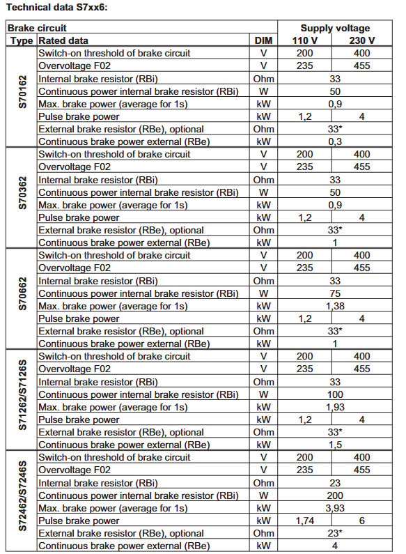
F02 DC bus overvoltage: 1. Input voltage exceeds the rated value (such as S7xx0 exceeding 480VAC); 2. Excessive braking power (failure to consume regenerative energy in a timely manner); 3. External braking resistor not connected. 1. Check the grid voltage and install a three-phase stabilized power supply; 2. Increase the power of the external braking resistor (such as S72402 with a 23 Ω/4kW resistor); 3. Connect the external braking resistor to the X8 terminal (remove the X8/3-X8/4 shorting bar)
F03 tracking error exceeds tolerance
1. Position loop gain (Kp) is too low; 2. The load inertia ratio exceeds the set value; 3. The motor current limit is too small. 1. Increase Kp through DRIVE GUI (such as adjusting from 0.5 to 1.0); 2. Reset the load inertia ratio (S2-5~S2-7 switches or software parameters); 3. Increase I2/RMS/I2 peak (not exceeding the rated value of the motor)
F04 feedback fault 1. Feedback cable breakage/short circuit; 2. Feedback equipment damage (such as encoder); 3. FBTYPE parameter setting error: 1. Use a multimeter to measure the continuity of the feedback cable (e.g. X1 terminal A+/A - resistance should be ≥ 1k Ω); 2. Replace feedback devices (such as EnDat encoder ECN1313); 3. Match FBTYPE with feedback type (e.g. BiSS-C set to 33)
F05 DC bus undervoltage 1. Input voltage too low (such as S7xx0 below 208VAC); 2. Power phase loss (S7xx0 three-phase phase loss); 3. Soft start circuit fault: 1. Check the grid voltage and eliminate the line voltage drop; 2. Measure the three-phase voltage of X0 terminal (deviation ≤ 5%); 3. Replace the soft start relay (located on the power board inside the amplifier)
F06 motor overheating 1. Motor PTC thermistor triggered; 2. The motor load exceeds the rated torque; 3. Poor heat dissipation of the motor: 1. Measure the PTC resistor of the motor (normal temperature ≤ 550 Ω, overheating ≥ 1330 Ω) and replace the thermistor; 2. Reduce the load or increase the motor model; 3. Clean the motor cooling channel and increase fan cooling
F27 STO operation fault 1. Simultaneous activation of STO signal and ENABLE signal; 2. STO circuit disconnection; 3. Safety card failure (S3/S4) 1. Ensure that the motor has stopped (speed ≤ 5rpm) before STO activation; 2. Check the wiring of X4A/3/X4B/6 (24V voltage is normal); 3. Reset the security card (power off for 8 minutes and restart)
(3) Special fault handling
Occasional faults caused by EMI interference (such as F17/A/D conversion errors)
Reason: The power cable and feedback cable are wired in parallel, with poor shielding grounding and large leakage current.
Solution:
The distance between the motor cable and the feedback cable should be ≥ 200mm, and they should be perpendicular at a 90 ° angle when crossing;
The feedback cable uses twisted pair shielded wire (such as Belden 82509, capacitance ≤ 120pF/m), and the shielding layer is grounded 360 ° through the amplifier front-end panel;
Connect a Corcom 6EQ1 power filter in series at the power input to reduce conducted interference.
DC bus parallel fault in multi axis system (such as F19/DC bus crash)
Reason: Different hardware versions of amplifiers are connected in parallel (such as mixing 01.21 and 02.20), and the DC bus cable is too long (exceeding 200mm).
Solution:
Ensure that the hardware versions of the parallel amplifiers are consistent (such as 02.20), and use 6mm ² shielded cables with a length of ≤ 200mm for the DC bus;
Connect KCM capacitor modules (such as KCM-S200, with a storage capacity of 1600Ws) in parallel at both ends of the DC bus to absorb regenerative energy;
Configure DC bus fuses (such as 30A/900VDC) for every group of 3 amplifiers to avoid individual failures affecting the overall system.
2、 Daily maintenance and lifecycle management
(1) Regular maintenance project (recommended cycle)
Standard requirements for maintenance project cycle operation content
Cooling system inspection: 1. Clean the dust on the fan filter every month; 2. Check the fan speed (S701 fan speed ≥ 2500rpm); 3. Measure the temperature of the heat sink. 1. There is no obvious dust accumulation on the filter screen; 2. The fan has no abnormal noise and the speed deviation is ≤ 10%; 3. The temperature of the heat sink during operation is ≤ 75 ℃
Quarterly inspection of wiring terminals: 1. Tighten the X0/X8/X9 terminal screws (torque 0.7-0.8Nm); 2. Check if the grounding of the cable shielding layer is loose; 3. Measure the conductivity resistance of the PE wire. 1. The terminals are not loose or oxidized; 2. The grounding resistance of the shielding layer is ≤ 0.1 Ω; 3. PE wire conductivity resistance ≤ 1 Ω
Feedback system verification every six months: 1. Read the feedback signal quality through DRIVE GUI (such as SinCos signal amplitude ≥ 1Vpp); 2. Test the forward and reverse positioning accuracy of the motor. 1. Signal amplitude deviation ≤ 10%; 2. Positioning error ≤ 0.1 ° (motor unloaded)
Monthly safety function testing: 1. Trigger the STO function and check if the motor has no torque output; 2. Test the SS1 function of the safety card S3/S4 (controlled motor shutdown after triggering). 1. The motor can rotate freely after STO activation; 2. After SS1 is triggered, the motor stops on an emergency stop ramp (≤ 1s from rated speed to 0)
(2) Long term storage and capacitor maintenance
Storage requirements
Environment: Temperature -25~55 ℃, humidity 5%~95% (no condensation), stacking height ≤ 8 boxes, away from corrosive gases/dust.
Over 1 year storage: The DC bus capacitor needs to be "reshaped" - disconnect all wiring, apply single-phase 230VAC to the X0 terminal for 30 minutes, to avoid capacitor capacity decay.
Capacitor lifespan management
Under normal operating conditions, the lifespan of DC bus capacitors is about 5 years (in a 40 ℃ environment), and the lifespan is halved for every 10 ℃ increase in ambient temperature.
Detection method: Use DRIVE GUI to read the DC bus voltage fluctuation (voltage ripple should be ≤ 5% under no-load), and replace the capacitor module (model KCM-E200) when the fluctuation exceeds 10%.
(3) Repair and scrapping process
Maintenance Request
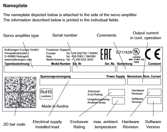
The faulty amplifier needs to be repaired through the official channels of Kollmorgen: fill out the repair application form (Appendix 10.3 of the manual), indicate the product model, serial number, and fault phenomenon, and send it to customer service in Europe (fax+49 (0) 2102-9394-3444) or China (fax+86-21-6128-9877).
Repair scope: Only authorized repair centers can disassemble amplifiers (unauthorized disassembly may cause warranty failure). Common repair components include power modules (IGBT), fans, and power boards.
scrap disposal
According to the requirements of the WEEE Directive (2002/96/EC), professional electronic waste disposal institutions are responsible for recycling, with a focus on separating metal casings, PCB boards, capacitors (including electrolytes), and prohibiting arbitrary disposal.
Before scrapping, it is necessary to clear the storage data (execute "Restore Default Configuration" through DRIVE GUI) to avoid parameter leakage.
3、 Preventive maintenance recommendations
environmental control
Install temperature sensors (such as PT100) inside the control cabinet. When the temperature exceeds 40 ℃, an alarm will be triggered and the linked axial fan (such as 24V/0.5A) will start;
Install a dehumidifier when the humidity exceeds 90% to prevent the PCB board from getting damp and short circuiting.
Software monitoring
Set up "maintenance reminders" through DRIVE GUI software (such as reminding to check the fan after running for 2000 hours), regularly backup parameters (saved as. par files), and avoid parameter loss;
Enable the "Fault Log" function (ASCII command LOGENABLE=1) to automatically record the time, current, and speed of the fault occurrence, making it easy to trace the root cause of the fault.
Spare Parts Management
It is recommended to reserve 1-2 sets of key spare parts (such as fans, power filters, and braking resistors), and the spare parts model should match the amplifier (such as S70102 fan model DE-200454, braking resistor model BAR-23-4kW).
- OMRON
- ABB
- General Electric
- EMERSON
- Honeywell
- HIMA
- ALSTOM
- Rolls-Royce
- MOTOROLA
- Rockwell
- Siemens
- Woodward
- YOKOGAWA
- FOXBORO
- KOLLMORGEN
- MOOG
- KB
- YAMAHA
- BENDER
- TEKTRONIX
- Westinghouse
- AMAT
- AB
- XYCOM
- Yaskawa
- B&R
- Schneider
- KONGSBERG
- NI
- WATLOW
- ProSoft
- SEW
- ADVANCED
- Reliance
- TRICONEX
- METSO
- MAN
- Advantest
- STUDER
- DANAHER MOTION
- Bently
- Galil
- EATON
- MOLEX
- DEIF
- B&W
- ZYGO
- Aerotech
- DANFOSS
- Beijer
- Moxa
- Rexroth
- Johnson
- WAGO
- TOSHIBA
- BMCM
- SMC
- HITACHI
- HIRSCHMANN
- Application field
- XP POWER
- CTI
- TRICON
- STOBER
- Thinklogical
- Horner Automation
- Meggitt
- Fanuc
- Baldor
- SHINKAWA
- Other Brands
- UniOP
- KUKA
- Iba
- Beckhoff
-
 Basler DECS-100-B15 Digital AVR
 -
 Basler 9284900103 PS DECS-400N
 -
 Basler D4N3H1U Intertie Protection
 -
 Basler DECS-100-B15 A15 AVR
 -
 Basler KR4F Voltage Regulator
 -
 Basler BE26434 T14 Transformer
 -
 Basler SR8A-2B15B3A Regulator
 -
 Westinghouse 774B472A12 AR Relay
 -
Basler DECS-100-B15 AVR
-
 Basler XR2002F Regulator 110V
 -
 Basler SR125-E Static Regulator
 -
 Basler SSR 125-12 Regulator
 -
 Basler MOC2599 Motor Pot
 -
 Basler BE1-DFPR Feeder Relay
 -
 Basler CBS 305 Current Boost
 -
 Basler BE1-25 AutoSync
 -
 Basler MVC 300 Voltage Control
 -
 Basler BE3-25A AutoSync
 -
 Basler KR7FF Static Regulator
 -
 Basler 90-49000-100 Regulator
 -
 Basler 880 kVA Dry Type Transformer Specs
 -
 Basler Electric BE1-25 Sync-Check Relay Specs
 -
 Basler SSR 125-12 Voltage Regulator Specs
 -
 Basler Electric BE1-851 Overcurrent Relay Review
 -
Basler Electric 149D930G02 Control Sub-Assembly
-
 Basler Electric BE1-81O/UT Frequency Relay Specs
 -
 Basler Electric BE1-51/27C Overcurrent Relay
 -
 Basler Electric 149D956G02 Industrial Component
 -
Basler Electric BE1-51A Overcurrent Relay Specs
-
 Basler Electric BE1-40Q Loss of Excitation Relay
 -
 Basler DECS-200 Excitation Control System
 -
 Basler DECS-200 Voltage Regulator 56-277V AC / 125V DC
 -
 Basler BE1-87T Transformer Differential Relay
 -
 Basler RDP-110-S1 Protection Relay
 -
 Basler BE1-700V Digital Protective Relay
 -
 Basler BE1-951 Overcurrent Protection System
 -
 Basler DECS-300 Digital Excitation Control
 -
 Basler DECS-200 Digital Excitation Control
 -
 Basler DECS-200-1C Excitation Control System
 -
Basler DECS-200-1L Digital Excitation Control
-
 Basler Electric BE1-GPS Generator Protection System
 -
Basler Electric DECS-200-1C Digital Excitation Controller
-
 Basler Electric DECS125-15 Excitation Control with Power Module
 -
 Basler Electric BE1-87G Differential Relay
 -
 Basler Electric BE1-11 Protection System I5A3M2P2N0EA00
 -
Basler Electric DECS-200-1C Excitation Control System
-
Basler Electric BE1-11g Generator Protection Relay
-
 Basler Electric DECS 125-15-B2C1 V2.0.9 Excitation Control
 -
 Basler Electric BE1-81O/UT3ED1JA7N2F Frequency Relay
 -
Basler Electric BE1-81O/UT3EE1YB7N1F Frequency Relay
-
 Basler Electric DECS-200-1L Digital Excitation Control System
 -
Basler DECS125-15-B2C1 Excitation Control
-
 Basler 9507900205 SSR Retrofit Voltage Regulator
 -
 Basler BE2000E Digital Voltage Regulator
 -
 Basler BE1-GPS Generator Protection System
 -
Basler DECS-250-CN1CN1N Digital Excitation Control
-
 Basler DGC-2020 Genset Controller
 -
 Basler BE1-81O UT3ED1LA7N0F Frequency Relay (Variant)
 -
 Basler BE1-81O UT3EE1YA9S0F Frequency Relay (Variant)
 -
Basler BE1-81O Over/Under Frequency Relay
-
Basler DECS125-15 Digital Excitation Control
-
Basler Electric BE1-951 Overcurrent Protection System
-
 Basler Electric BE1-700V Digital Protective Relay
 -
 Basler Electric APR63-5 Automatic Voltage Regulator
 -
Basler Electric BE1-851 Overcurrent Protection System
-
Basler Electric DECS-250-LN1SN1N Excitation Control
-
 Basler Electric BE1-87T Transformer Differential Relay
 -
Basler Electric DECS-200-1L Excitation Control System
-
 Basler Electric 9310300100 DECS-300 Excitation Control
 -
 Basler Electric SSE-N 125-4.5KW Shunt Exciter Regulator
 -
 Basler Electric DGC-2020HD-5NS1DNSBA Genset Controller
 -
Basler Electric BE1-81-O/UT3EE1JB7N1F Frequency Relay
-
Basler Electric BE1-81T1EE1WA0N1F Frequency Relay
-
 Basler Electric BE1-25M1EA6PN5R1F Sync-Check Relay
 -
 Basler Electric BE1-GPS Generator Protection System
 -
Basler Electric DECS-250-LN1SN1N Excitation Control Rev V
-
 Basler Electric DECS-250-CN2CN1N Excitation Control
 -
Basler Electric BE1-50/51B-207 Overcurrent Relay
-
Basler Electric DECS-300-C0N0 Excitation Control System
-
Basler Electric DECS-200 Digital Excitation Control System
-
Basler Electric DECS-250-LN1CN1N Excitation Unit
-
Basler Electric DECS-250 LN2SA1D Excitation Unit Specs
-
Basler Electric BE1-87T Transformer Relay Review
-
Basler Electric BE1-11 Protection System
-
Basler Electric BE1-GPS100-E4N1H1N Protection System
-
 Allen-Bradley 442G-MABH-R Safety Module
 -
 Beckhoff CX1030-0111 PLC Assembly Profile
 -
 FANUC IC693CPU364 PLC Module
 -
 Orange Denmark Type 200816 220 PLC Specs
 -
 OMRON C200H-SNT31 Sysmac PLC Module
 -
 Allen Bradley 20AB022A3AYNANC0 PowerFlex 70
 -
 OMRON C200HW-PCU01 Position Control Unit
 -
 ABB AO845A-eA Analog Output Module
 -
 OMRON CJ1M-CPU22 CPU Unit
 -
 Allen Bradley 100-E265ED11 Contactor
 -
 Honeywell 51304511-100 Interface Module
 -
 SOLEXY BXF3S0101N0018 Gateway Module
 -
 OMRON CJ2H-CPU65 CPU Unit
 -
 Automation Direct GS2-45P0 AC Drive
 -
 M68-2000 2-Axis Motion CNC Controller
 -
 OMRON CJ1M-CPU11 V3.0 PLC CPU Unit
 -
 OMRON CJ1W-NC413 4-Axis Positioning Controller
 -
 OMRON 3G2A3-PRO16 Programming Console HMI
 -
 Siemens 3VT8440-2AA04-2GA2 Molded Case Circuit Breaker
 -
 Siemens 3RT5045 Contactor Series
 -
 OMRON C200HS-CPU01-E SYSMAC PLC Controller
 -
 OMRON C500-NC103-E Positioning Control Unit
 -
 OMRON CJ1W-TC001 Temperature Control Unit
 -
 OMRON NJ301-1100 NJ-PA3001 PLC System EtherCAT
 -
 Pilz 773100 M1P Safety Relay Base Unit
 -
 Siemens SINUMERIK 840D SL NCU 720.3B with PLC 317-3 PN/DP
 -
 Siemens 6AV6618-7GD01-3AB0 HMI Panel
 -
 OMRON F150-C15E-3 Vision Mate Controller PLC Overview
 -
 Mitsubishi MELSEC A Series PLC System A63P A3ACPU A616AD A68RD3
 -
 M68-2000 2 Axis Motion Controller SCE SERVO CNC
 -
 OMRON FZ-S2M PLC Camera Vision System
 -
 VISOLUX SLVA-4K PLC Module from Elektronik GmbH
 -
 OMRON CJ1M-CPU23 V2.0 PLC CPU Unit
 -
 ABB AI86-16CHF PCB Card 5761751-9 B Specifications
 -
 Allen-Bradley 100-D140ZJ22L Contactor Overview
 -
 Merlin Gerin PB80 PLC Rack
 -
 WEIR WE203 Power Supply PLC
 -
 OMRON NX-TS3102 Temperature Input Unit
 -
 Siemens 6ES7146-6FF00-0AB0 I/O Module
 -
 Fanuc A16B-3300-0057 Circuit Board
 -
 OMRON CJ1W-IDP01 Input Module
 -
 Siemens 6FX2007-1AD13 Handheld Unit
 -
 Gems EM54 PLC Module PCB


