
SINAMICS A10: Intelligent Servo Drive System with Integrated Safety and Efficient Debugging
SINAMICS A10: Intelligent Servo Drive System with Integrated Safety and Efficient Debugging
Introduction
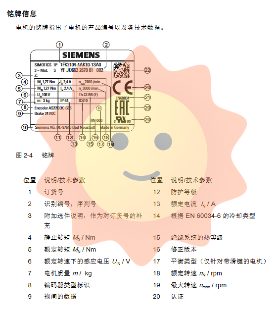
SINAMICS A10 is a compact single axis servo drive system launched by Siemens, designed specifically for high dynamic performance industrial automation applications. The system is perfectly matched with SIMOTICS S-1FK2 servo motors and pre installed MOTION-CONNECT cables, forming a highly integrated, easy to debug, and safe reliable drive solution. This article is based on its official operating manual (firmware version V5.2, January 2019), providing in-depth analysis of its system architecture, core security functions, installation and debugging process, and key technical points, providing engineers with comprehensive professional references.
System Overview and Design Philosophy
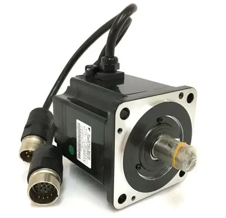
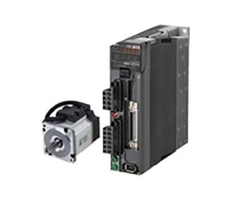
The SINAMICS A10 drive system consists of three core components: SINAMICS A10 driver, SIMOTICS S-1FK2 servo motor, and MOTION-CONNECT cable using One Cable Connection (OCC) technology. The system is connected to the upper controller (such as SIMATIC S7-1500) through PROFINET and supports real-time (RT) and synchronous real-time (IRT) communication.
The design of the driver emphasizes compactness and high performance, with a power range covering 0.1 kW to 0.75 kW for single-phase 230V version and 0.4 kW to 7 kW for three-phase 400V version. Its key features include:
Integrated safety functions: Safety functions that comply with SIL 2/PL d/Cat.3 standards can be achieved without the need for external components.
Optimization matching: The driver has undergone servo control optimization for the 1FK2 motor to ensure optimal dynamic response.
Network server integration: Built in web server, supports debugging, diagnosis, and parameter settings through standard browsers, without the need for specialized software.
Core safety function: Driver Integrated Safety
Safety is the core advantage of SINAMICS A10. The integrated security functions are divided into two categories, both of which perform security monitoring with a cycle of 4ms.
1. Basic Functions
Included in the standard supply scope of the drive, no additional authorization is required:
Safe Torque Off (STO): Complies with EN 60204-1 stop category 0, immediately blocks motor torque output to prevent accidental restart. Suitable for situations where the motor can safely stop by inertia.
Safe Stop 1 (Time Controlled) (SS1-t): Meets Stop Category 1, drives the braking along the OFF3 slope, and triggers STO after a preset delay time. Suitable for situations where the load friction torque is insufficient or there is a risk of inertia parking. There are two modes to choose from: Drive Self Control (SS1-t) or Stop by External Controller (SSSE-t).
Safe Brake Control (SBC): linked with STO, controls the motor brake to close, preventing the hanging load from sagging. Suitable for applications such as lifting and coiling.
2. Extended Functions
Additional license activation is required to provide richer security monitoring:
Safe Stop 2 (SS2): Stop the motor and reliably monitor the stationary position (transition to SOS state), and resume operation without returning to zero after cancellation.
Safe Operating Stop (SOS): Reliable closed-loop monitoring of the stationary position of the drive to resist external forces.
Safely Limited Speed (SLS): Safety monitors whether the speed exceeds the preset limit (up to 4 switchable gears), and triggers a preset stop response if it exceeds the limit.
Other functions include Safety Speed Monitoring (SSM), Safety Direction (SDI), Safety Limited Acceleration (SLA), and Safety Braking Test (SBT) for diagnosing brake performance.
The safety function can be controlled through Fault Safety Digital Input (F-DI) or PROFIsafe communication (recommended message 30 for basic functions and message 901 for extended functions). The system has detailed response time analysis and error tolerance processing to ensure the reliability and timeliness of safety response.
Installation and configuration points
Correct installation and configuration are the foundation for reliable system operation.
1. Electromagnetic compatibility (EMC) installation
To ensure stable operation, EMC guidelines must be followed:
Control cabinet: Use metal mounting plates with good grounding, and install shielding plates for cable shielding layer extraction.
Cable wiring: Distinguish between high interference level cables (motor cables, brake resistor cables) and low interference level cables (signal/data cables). The two should be laid separately, with a minimum spacing of 25cm, and intersect at a right angle. Be sure to use shielded cables with both ends grounded.
Motor cable length: Depending on whether an external filter is used and whether a DC bus is shared, the allowed cable length ranges from 10 meters to 250 meters and must strictly comply with the manual regulations.
2. Grid connection
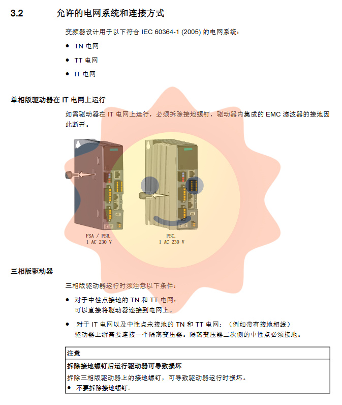
Support TN, TT, and IT power grid systems. When operating in IT power grids or phase line grounding systems, special attention should be paid to removing specific grounding screws for single-phase drivers, and additional isolation transformers may be required for three-phase drivers.
Provide options for input cascading and common DC bus. The common DC bus allows up to 6 drivers to parallel the DC bus, effectively recovering braking energy and reducing the use of external braking resistors. Drivers need to be arranged in descending order of power during construction.
3. Braking resistor configuration
The driver is integrated with an internal braking resistor. When the regenerative energy generated by motor braking exceeds its capacity, an external braking resistor needs to be connected. The manual provides detailed formulas for calculating braking energy and a selection table for external resistors (including continuous power, peak power, and resistance value requirements), and emphasizes the importance of using intrinsically safe resistors with temperature monitoring function, which must be activated on the driver side (through digital input DI4).
Debugging and Diagnosis: Application of Network Server
The revolutionary feature of SINAMICS A10 lies in its integrated network server debugging interface.
1. Debugging process
Debugging can be performed by accessing the driver service interface (default IP: 169.254.11.22) through a browser (supporting Chrome, Firefox, Edge, Safari, etc.). The main steps include:
Basic settings: Set the driver name and adjust the motor rotation direction.
One click optimization (OBT): Automatically optimizes the control parameters of the driver speed loop and current loop, and users can choose "conservative", "standard", or "dynamic" optimization modes.
Parameter settings: Configure speed/torque limits, brake control parameters, digital input functions (such as probes, external brake resistor temperature monitoring), etc.
Security integration debugging: Through a wizard interface, gradually configure security functions, select control methods (PROFIsafe/F-DI), set delay time, differential time, etc., and set security passwords to prevent unauthorized modifications.
Data backup and recovery: It is easy to backup all parameters to local files or restore settings from files, making it convenient for batch debugging or device replacement.
2. Diagnosis and maintenance
The network server provides a comprehensive diagnostic view:
Message Center: Centralized display of fault and alarm information, supporting filtering and viewing of details.
Drive status: Real time monitoring of key parameters such as speed, torque, current, temperature, etc.
Communication status: Display IP address, PROFINET connection status, and process data exchange status.
Security diagnosis: The dedicated page displays information such as the activation status of security functions, mandatory potential fault check (Teststop) timer, security logs (CRC checksum and changes), etc., for easy tracking of security status and recording of acceptance testing documents.
Technical advantages and application areas
The SINAMICS A10 servo drive system excels in the following areas with its high integration, excellent safety, and minimalist debugging experience:
Robots and robotic arm systems
Packaging, plastic, and textile machinery
Printing machinery
Glass, ceramic, stone and wood processing machinery
The system deeply integrates security functions into the driver, reducing the number of external security components and wiring complexity, while lowering debugging thresholds and maintenance costs through standardized network interfaces. The pre installed OCC cable and optimized motor driver combination ensure high reliability and consistent performance for plug and play use.
- ABB
- General Electric
- EMERSON
- Honeywell
- HIMA
- ALSTOM
- Rolls-Royce
- MOTOROLA
- Rockwell
- Siemens
- Woodward
- YOKOGAWA
- FOXBORO
- KOLLMORGEN
- MOOG
- KB
- YAMAHA
- BENDER
- TEKTRONIX
- Westinghouse
- AMAT
- AB
- XYCOM
- Yaskawa
- B&R
- Schneider
- Kongsberg
- NI
- WATLOW
- ProSoft
- SEW
- ADVANCED
- Reliance
- TRICONEX
- METSO
- MAN
- Advantest
- STUDER
- KONGSBERG
- DANAHER MOTION
- Bently
- Galil
- EATON
- MOLEX
- DEIF
- B&W
- ZYGO
- Aerotech
- DANFOSS
- Beijer
- Moxa
- Rexroth
- Johnson
- WAGO
- TOSHIBA
- BMCM
- SMC
- HITACHI
- HIRSCHMANN
- Application field
- XP POWER
- CTI
- TRICON
- STOBER
- Thinklogical
- Horner Automation
- Meggitt
- Fanuc
- Baldor
- SHINKAWA
- Other Brands
- UniOP
- KUKA
- Iba
-
 ABB SCC-C 23070-0-10232110 gas cooler
 -
 Sick LGTN101-521 CPU Module
 -
 Okuma 1911-2836 PLC Circuit Board
 -
 Mitsubishi Melsec PM-120M PLC
 -
 Omron F210-C15 Vision Mate Controller System
 -
 Siemens 7ML5110-1GD07-4AF3 Ultrasonic Level Gauge
 -
 ABB Pluto S46 V2 Safety Relay
 -
 Omron Z3RN-5A Optical Serial Link
 -
 Omron R7D-APA3H 30W Servo Drive
 -
 Giddings Lewis 502-03638-41R3 PLC Processor
 -
 Omron SCY-P1 Sequencer Controller
 -
 Siemens C98043-A7002-L1-13 PCB Board
 -
 SACS TECNICA Palletizer PC PLC Control System
 -
 AutomationDirect T1F-14THM PLC Module T1F14THM
 -
 OMRON C200H-AD003 Analog Input Unit PLC Module
 -
 Applied Materials 0010-A0000 Electricity Box PLC 200mm
 -
 ABB RVT-6 Power Factor Controller RVT6
 -
 Allen-Bradley 2094-BC01-MP5-M Kinetix 6000 Axis Module
 -
 OMRON FQM1S-MC233 Motion Controller PLC Module
 -
 OMRON C200H-SNT31 PLC Special I-O Module
 -
 Yaskawa SGMPH-04AAA61D-OY Servo Motor 400W 200V
 -
 Yaskawa SGMGH-09DCA6F-OY AC Servo Motor 850W 400V
 -
 REFU ELEKTRONIK SR17002 PLC Logic Module Circuit Board
 -
 Siemens 6DP1231-7AA PLC Board Module Industrial Control
 -
 ABB SACE ISOMAX S3 N 160 Molded Case Circuit Breaker
 -
 OMRON C120-SC024-V1 SYSMAC C120 Compact PLC Unit
 -
 OMRON CJ1W-SCU41-V1 Serial Communication Unit PLC Module
 -
 OMRON 3G3MX2-A4110-ZV1 MX2 Variable Frequency Drive
 -
 Yaskawa SGDH-04AE-OY Sigma-II Servo Driver 400W 200V
 -
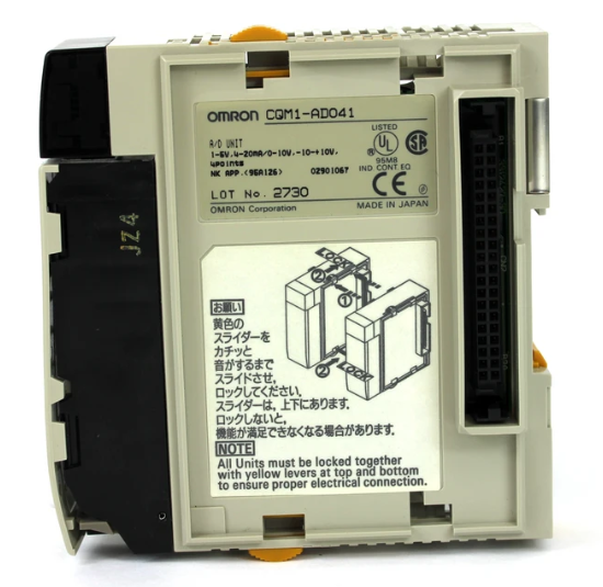 OMRON CQM1-AD041 Analog Input Module PLC I/O Unit
 -
 Delta Omega XML2-0060-45-4/S-A Servo Drive
 -
 Omron CJ1W-AD041 Analog Input
 -
 Omron CJ1W-NC271 Position Control Unit
 -
 Omron CJ1G-CPU45H PLC CPU
 -
 Omron CJ1W-EIP21 EtherNet/IP Unit
 -
 Omron F210-C15 Vision Mate Controller
 -
 Omron CQM1H-ADB21 Analog I/O Board
 -
 Omron GRT1-PRT PROFIBUS DP-V1 Adapter
 -
 Omron CP1H-Y20DT-D PLC CPU
 -
 TE.CO TFX 4G 1.5 Grey Cable 470m
 -
 Yaskawa SGDH-04AE-OY Servo Driver 400W 200V
 -
 OMRON CJ1H-CPU66H V4.0 PLC CPU
 -
 OMRON R7M-A10030-BS1 Servo Motor 200W 100V
 -
 OMRON FQM1-MMA21 Motion Controller
 -
 Yaskawa SJDE-08APA Servo Amplifier
 -
 OMRON CQM1-AD041 Analog Input Unit
 -
 Siemens OCI55 Dialogue Module Landis
 -
 OMRON F350-C10E Image Processing Unit
 -
 OMRON NT10S-SF121 HMI Terminal
 -
 SIEMENS 3RB1262-0LB31 Overload Relay
 -
 OMRON YASKAWA SGDS-02A12A Servo Drive
 -
 TE.CO TFX 4G 1.5 Grey Cable ST 500m
 -
 FANUC A16B-3200-0362 PCB Control Board
 -
OMRON CQM1-ARM21 Analog Output Unit
-
 Allen-Bradley 1788-EN2DN Ethernet DeviceNet Gateway
 -
 Siemens 3VL9440-7EE40 3VL4740-2AA46-0AA0 Circuit Breaker
 -
 OMRON CJ1W-AD041-V1 Analog Input Unit
 -
 OMRON CQM1-AD041 CQM1-IPS02 Analog Input Power Supply
 -
 Texas Instruments System 505 PLC 525-110 525-1102
 -
 OMRON CQM1-AD042 Analog Input Unit
 -
 Yaskawa SGDH-04AE-OY Servo Driver 200V 400W
 -
 CTI 2512 75W Power Supply for CTI 2500
 -
 Omron F300-B5 Image Processing Unit
 -
 Mitsubishi 15050-PR01A PLC Board
 -
 Omron CQM1-TC101 Temperature Controller
 -
 SCE M68-2000 2 Axis Motion Controller HW 2.3/B
 -
 Omron 3Z4SP-C22 Visual Positioning Sensor
 -
 Omron 3G3SV-BB007-E 0.75kW VFD
 -
 CML 6622 IRD Entek AW10528 Vibration Monitor
 -
 Omron CP1L-EL20DR-D PLC CPU
 -
 TE.CO TFX 4G 1.5 Grey Cable 500m
 -
 Mitsubishi Electric 3BK23057 Circuit Board Module
 -
 OMRON FQM1-MMP21 Motion Control Module
 -
 OMRON CP1E-E40SDR-A Micro PLC CPU Unit
 -
 KEBA CU201 PLC Control Unit
 -
 OMRON F150-C10E-2 Vision Sensor Controller
 -
 YASKAWA SGDH-04AE-OY Sigma-II Servo Driver
 -
 OMRON CS1H-CPU65-V1 PLC Central Processing Unit
 -
 OMRON NB7W-TX01B Interactive Display HMI
 -
 OMRON C500-TU002E Programmable Logic Controller Timer Unit
 -
 OMRON C200HW-PRT21 PROFIBUS DP Slave Unit
 -
 ExcelTech MX-5-S-I-6-4 Static Transfer Switch
 -
 Allen-Bradley 100-B300ND3 Contactor 304A 600V
 -
 Pasaban MTC-3052 Fast I/O PLC Card
 -
 OMRON CQM1-TC101 Temperature Control Unit
 -
 OMRON 3G3SV-BB007-E VFD 0.75kW 220V
 -
 OMRON CQM1H-MAB42 PLC Module
 -
 OMRON R88M-K75030T-S2 Servo Motor
 -
 Yaskawa SGMAH-03DAAA61 Servo Motor 200V 300W
 -
 OMRON F300-P Power Supply Unit
 -
 Land System 4 M1 Thermometer 65071800C-L35-A50
 -
 Yamatake MAH10-ME0100 ME-NET Module
 -
 Siemens Simatic 505 16 Slot PLC Rack
 -
 Yaskawa SGDH-02AE-OY Servo Driver 200W
 -
 SCE M68-2000 2-Axis Motion Controller
 -
 Zenith Controls K-1201 Transfer Switch Controller
 -
 Yaskawa SGDH-02AE-OY 200W Servo Driver
 -
 Yaskawa SGMAH-02AAA61D-0Y 200W Servo Motor
 -
 Schneider TSX P573634M Modicon Premium CPU
 -
 Siemens 6FX5002-5DN31-1DA0 Power Cable
 -
 Omron CJ1G-CPU43H CPU Unit 30K Steps
 -
 OMRON C28P-EDR-D PLC Unit
 -
 SIEMENS S7-300 PLC System
 -
 Schneider TP400-PLC-1411 Board
 -
 Siemens 6FC5203-0AF00-0AA3 Panel
 -
 ALLEN BRADLEY 1754-L28BBB GuardPLC
 -
 Omron E6C3-AG5B-C Encoder
 -
 SCE M68-2000/5 CNC Controller
 -
 SCHNEIDER TM2ALM3LT Module
 -
 OMRON C200H-OV001 Voice Module
 -
 OMRON R88M-H30030 Servo Motor
 -
 Bosch RD500 Indramat Servo Drive RD51.2-4B
 -
 Siemens 6SE7090-0XX84-0AH2 T300 Module
 -
 Omron GRT1-TS2P SmartSlice Thermocouple Input
 -
 Xaar XP55500016 XUSB Drive Electronics
 -
 Siemens 6SL3210-1SE21-8UA0 PM340 Power Module
 -
 Mitsubishi GT2708-VTBA Touch Display 8.4 Inch
 -
 Pasaban Fast I/O MTC-3052 PLC Card
 -
 ABB ACS355-01U-02A4-2 VFD 0.37kW
 -
 Yamatake MAH20-PC2100 Processor Module
 -
 Allen Bradley 1774-P1 PLC Power Supply
 -
 Yaskawa SGDH-04AE-OY 400W Servo Driver
 -
 Omron CPH-X40DT1-D PLC CPU Unit
 -
 Pilz PNOZ mm0.2p Safety PLC Mini 772002
 -
 Siemens 6SL3555-OPR01-0AA0 Sinamics G110M Panel
 -
 Sanyo PLC-XTC50L LCD Projector
 -
 SCE M68-2000 2-Axis Motion Controller
 -
 Omron CS1W-CT021 High-Speed Counter Unit


