
Watlow Series 146 Temperature Regulator
Watlow Series 146 Temperature Regulator
Product basic information
Core positioning: A DIN rail mounted temperature regulation controller that supports thermocouple or RTD sensor input, with both DIN rail quick installation and embedded installation methods. Designed for various safety application scenarios, it can achieve high/low limit temperature control and is suitable for industrial heating equipment, commercial cooking equipment and other scenarios that require temperature safety protection, such as ovens, reactors, heaters, etc.
Core Features and Advantages
Flexible and convenient installation: Supports DIN EN50022 standard 35mm × 7.5mm rail installation, which can be completed with simple manual tools. Embedded installation can also be selected to adapt to different installation environment requirements.
Diverse control modes: The factory can preset high/low limit control modes, support manual or automatic reset after power failure, and meet different safety control logics; Equipped with temperature over limit latch alarm function, requiring manual reset to enhance safety and reliability.
Intuitive and easy to understand operation: equipped with output status LED indicator lights, providing real-time feedback on working status; Support built-in/remote adjustable or fixed setpoints, calibrated dial to compensate for sensor nonlinearity errors; Simultaneously compatible with both Celsius (° C) and Fahrenheit (° F) temperature scales, suitable for different usage habits.
Comprehensive safety protection: equipped with thermocouple and RTD disconnection protection function, automatically cutting off output in case of sensor failure to avoid equipment damage; Obtained multiple certifications such as CE and FM Class 3545, compliant with EN61010 safety standards, EN61326 industrial electromagnetic compatibility standards (Class B emission), installation category II, pollution level 2, suitable for specific scenarios such as commercial cooking.
Strong adaptability: Supports multiple thermocouple (E, J, K, T type, etc.) and RTD (100 Ω, 1000 Ω) inputs, with optional power supply voltages of 24VAC, 120VAC, 230-240VAC to meet different on-site power supply and sensing needs.

Product Technical Specifications
(1) Control and operation specifications
Control mode: The factory can choose high limit or low limit control; The power-off reset mode can be selected manually or automatically; When the temperature exceeds the limit (too high/too low), a latch alarm is triggered and manual reset is required; Support built-in reset switch or external reset switch provided by the user.
Operation interface: LED indicator light displays output status (power on/off); Adjustable set point (built-in/remote) equipped with calibration dial to compensate for sensor nonlinearity; Fixed set point factory calibration according to user specified values; Dual temperature scale (° C/° F) switching.
(2) Enter specifications
Sensor type: Supports thermocouples (E, J, K, T, etc.) or platinum resistance RTDs, thermocouples have automatic cold junction compensation function, and can choose isolation or grounding type; RTD supports 2-wire or 3-wire system, calibrated at 100 Ω @ 0 ° C, and conforms to the 0.003850 Ω/Ω·° C curve.
Input protection: thermocouple and RTD disconnection protection function, automatically cuts off the output when the sensor is disconnected, preventing equipment from losing control.
Measurement range: Depending on the sensor type and model configuration, for example, E-type thermocouple 0-799 ° C (32-1470 ° F), J-type thermocouple 0-315 ° C (32-600 ° F), T-type thermocouple -200-350 ° C (-328-662 ° F); RTD measurement range -73-600 ° C (-100-1112 ° F), etc., fixed set points can be customized according to user needs (such as 200 ° C, 350 ° C, etc.).
(3) Output specifications
Output type: 8A electromagnetic relay, Form C (single pole double throw, SPDT), rated load: 8A@240VAC (obstructive) 8A@28VDC (Resistive), with a rated load of 275VA, can directly drive small heating equipment, contactor coils, and other loads.
Load protection: When switching inductive loads (such as relay coils, solenoid valves, etc.), an RC suppressor (Watlow recommended model Quencharc, part number 0804-0147-0000) needs to be installed to avoid electromagnetic interference damaging the controller.
(4) Accuracy and stability
Calibration accuracy: The adjustable set point (built-in/remote) is within ± 1% of the range at an ambient temperature of 25 ° C ± 3 ° C (77 ° F ± 5 ° F) and a rated line voltage of ± 1%, with a minimum range of 540 ° C (1000 ° F); The fixed set point has an error of ± 6 ° C/± 10 ° F under the same environmental and voltage conditions.
Setpoint accuracy: The precision of the adjustable set point dial is ± 3%.
Temperature stability: When the thermocouple is input, for every 1 ° C change in ambient temperature, the input reference drift typical value is 9 µ V/° C (5 µ V/° F); When inputting RTD, for every 1 ° C change in ambient temperature, the typical drift value is 0.2 ° C/° C (0.2 ° F/° F).
Voltage stability: For every 1% change in rated line voltage, the range drift is ± 0.01% (minimum range 540 ° C or 1000 ° F).
(5) Power and environmental specifications
Power parameters: Supports 24VAC (+10%/-15%), 120VAC (+10%/-15%), 230-240VAC (+10%/-15%), frequency 50/60Hz, maximum power consumption 10VA, power type needs to be specified by model (such as 1=120VAC, 2=230-240VAC, 3=24VAC).
Environmental conditions: working temperature 0-55 ° C (32-131 ° F), storage temperature -20-85 ° C (-4-185 ° F); Relative humidity 0-90% (non condensing), suitable for most industrial and commercial environments.
(6) Physical and installation specifications
Dimensions: Width 60mm (2.28 inches), height 115mm (4.45 inches), depth 100mm (3.89 inches), weight 0.3kg (0.7 pounds).
Terminal specifications: Captive screw cage clamping connection, supports maximum 4mm (0.155 inch) screwdriver head operation, compatible with 14-30 gauge wires.
Installation method: DIN rail installation (compatible with 35mm × 7.5mm rails) or embedded installation. Embedded installation requires drilling two 5mm (0.19 inch) holes on the panel and fixing them with # 8-32 screws.
Installation and Wiring Guide
(1) Installation process
1. Sub Panel Mounting
Attention: FM certification requires that limit switches be appropriately closed to reduce arbitrary adjustments to the set temperature.
Step 1: Use the controller as a template and mark two installation hole positions on the panel (refer to the hole size in Figure 2a of the document).
Step 2: Drill two 5mm (0.19 inch) diameter holes at the marked location.
Step 3: Use two # 8-32 screws to secure Series 146 to the panel.
2. DIN Rail Mounting
Step 1: Align the upper mounting clip of the controller with the upper edge of the DIN rail (refer to Figure 2b in the document).
Step 2: Press firmly on the upper edge of the front part of the controller, and the controller will be firmly fixed on the guide rail in a "snap" manner; If it cannot be fastened, check if the guide rail is bent. The clamping distance range of the guide rail is 34.8mm (1.37 inches) to 35.3mm (1.39 inches).
3. Disassemble from DIN rail
Step 1: Use your fingers to hold down the release lever at the bottom of the controller.
Step 2: Gently press the top of the controller (above terminals 1-9) and pull the release lever forward to remove the controller.
(2) Wiring specifications
1. General wiring rules
Use sensor types that match the device label model to ensure correct polarity of thermocouples or RTDs.
Thermocouples should be insulated from the installation surface during installation to avoid input errors caused by thermal conduction; Thermocouple leads should be made of twisted pair wires, wired separately, and kept away from other circuits.
In environments with severe electromagnetic interference (such as frequent switching of contactors, motors, and solenoid valves), shielded thermocouple leads should be used, and the shielding layer should only be grounded at the sensor end.
All wiring and fuse configurations must comply with the National Electrical Code (NEC NFPA70) and applicable local regulations; The independent load voltage needs to be fused on the L1 (live) side and connected to the common terminal (COM) of the relay.
It is recommended to install a power isolation switch near the controller to cut off the power supply in case of controller failure; The lead resistance of a 2-wire RTD can introduce errors (every 1 Ω lead resistance leads to additional errors). It is recommended to use a 3-wire RTD to compensate for lead resistance, and the three extension wires must have the same resistance (same wire gauge, copper stranded wire).
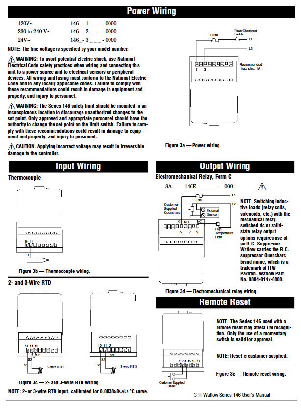
2. Power wiring
The power supply type is specified by the model: 120VAC corresponds to model 146_ -1_ -00000 230-240VAC corresponds to 146-2_ -0000, 24VAC corresponds to 146-3_ -0000.
Warning: To avoid the risk of electric shock, wiring must comply with national electrical safety standards. All wiring and fuses must comply with NEC and local regulations, otherwise it may cause equipment damage, property damage, or personal injury; The controller should be installed in an inconspicuous location to prevent unauthorized personnel from adjusting the set point. Only authorized personnel can operate the set point change, and unauthorized operation may cause safety risks; Applying incorrect voltage can cause irreversible damage to the controller.
3. Input wiring
Thermocouple wiring: Connect the positive and negative poles to the corresponding terminals as shown in Figure 3b of the document to ensure that the cold end compensation function is normal. Isolation and grounding thermocouples should be wired according to the model requirements.
RTD wiring: Refer to Figure 3c in the document for the wiring methods of 2-wire and 3-wire RTDs. The three leads of the 3-wire RTD need to have the same resistance. When wiring, pay attention to the correspondence between terminals S1 and S3 to ensure that the calibration curve matches (0.003850 Ω/Ω·° C).
4. Output wiring
The wiring of the electromagnetic relay (Form C type) should refer to Figure 3d in the document. The load should be connected in series between the normally open (NO) or normally closed (NC) terminal and the common terminal (COM). A fuse (recommended specification 1A) should be installed on the L1 side, and an RC suppressor should be connected in series for inductive loads.
5. Remote reset wiring
The remote reset switch is provided by the user, and the wiring method refers to Figure 3e in the document (terminals 13, 15, 16, 17, 14). Only the momentary switch meets FM certification requirements, and remote reset may affect the validity of FM certification.
6. System wiring example
Typical system wiring includes components such as power isolation switches, fuses, controllers, sensors, loads (heaters), contactors, solid-state relays, etc. Please refer to the two system wiring schemes in Figure 4 of the document to ensure that the power supply, input, output, and reset circuit wiring are complete and comply with safety regulations.
Model selection and order information
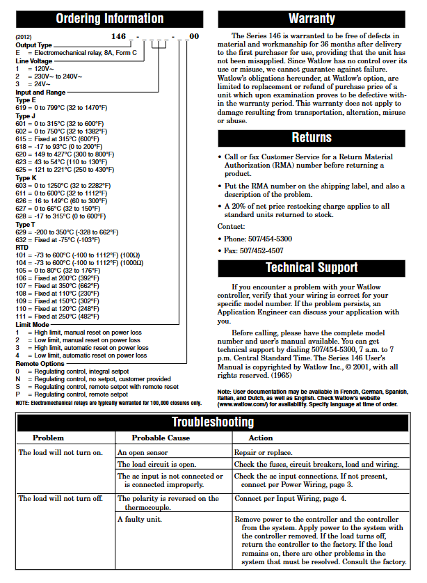
(1) Model Structure
The model format is 146E - (1/2/3) (100-999) - (1/2/3/4) (any three letters/numbers), and the meanings of each part are as follows:
146E: Product series and output type, E=8A electromagnetic relay (Form C type).
Line voltage code: 1=120VAC, 2=230-240VAC, 3=24VAC.
Input and Range Code: Represents sensor type and measurement range, for example:
E-type thermocouple: 619=0-799 ° C (32-1470 ° F).
J-type thermocouple: 601=0-315 ° C (32-600 ° F), 602=0-750 ° C (32-1382 ° F), 615=fixed 315 ° C (600 ° F), etc.
K-type thermocouple: 603=0-1250 ° C (32-2282 ° F), 611=0-600 ° C (32-1112 ° F), etc.
T-type thermocouple: 629=-200-350 ° C (-328-662 ° F), 632=fixed -75 ° C (-103 ° F), etc.
RTD: 101=-73-600 ° C (-100-1112 ° F, 100 Ω), 104=-73-600 ° C (-100-1112 ° F, 1000 Ω), 106=fixed 200 ° C (392 ° F), etc.
Limit mode code: 1=high limit+power-off manual reset, 2=low limit+power-off manual reset, 3=high limit+power-off automatic reset, 4=low limit+power-off automatic reset.
Remote option codes: 0=adjustable control+built-in setting potentiometer, N=adjustable control+no setting potentiometer (provided by the user), S=adjustable control+remote setting potentiometer+remote reset, P=adjustable control+remote setting potentiometer.
(2) Selection precautions
Confirm the on-site power supply voltage and select the corresponding line voltage code (1/2/3).
Select the sensor type (thermocouple/RTD) and corresponding range code based on the temperature measurement range and accuracy requirements, and specify the target temperature for the fixed set point.
Select the limit mode (high/low limit) and power-off reset mode (manual/automatic) according to safety control requirements.
Select remote options according to installation and operation requirements (built-in/remote setpoints, whether remote reset is required).
The warranty period for electromagnetic relays is usually 100000 closing operations, and the service life needs to be evaluated in conjunction with the load switching frequency.
Troubleshooting and Maintenance
(1) Common faults and solutions
Possible causes and solutions for the fault phenomenon
Load cannot start sensor open circuit maintenance or replacement of sensor
Check if the fuse, circuit breaker, load, and wiring of the load circuit are normal for an open circuit
Check the AC input connection according to the "Power Wiring" section (page 3) if it is not connected or connected incorrectly. If it is not connected, reconnect it
The load cannot be turned off. Connect the thermocouple correctly by reversing the thermocouple according to the "Input Wiring" section (page 4)
Controller failure cuts off the power supply of the controller and removes it from the system, only supplying power to the system; If the load is turned off, it indicates a controller malfunction and needs to be returned to the factory for repair; If the load is still running, it indicates that there are other faults in the system. Please contact the factory for consultation
(2) Maintenance
Regularly check whether the wiring terminals are loose, whether the sensors are damaged or aged, and ensure reliable connections.
Keep the controller clean, avoid dust and oil accumulation, and stay away from corrosive environments and severe vibrations.
Regularly verify the accuracy of set points and the reliability of output actions, and promptly troubleshoot sensor or wiring issues if any abnormalities are found.
- OMRON
- ABB
- General Electric
- EMERSON
- Honeywell
- HIMA
- ALSTOM
- Rolls-Royce
- MOTOROLA
- Rockwell
- Siemens
- Woodward
- YOKOGAWA
- FOXBORO
- KOLLMORGEN
- MOOG
- KB
- YAMAHA
- BENDER
- TEKTRONIX
- Westinghouse
- AMAT
- AB
- XYCOM
- Yaskawa
- B&R
- Schneider
- KONGSBERG
- NI
- WATLOW
- ProSoft
- SEW
- ADVANCED
- Reliance
- TRICONEX
- METSO
- MAN
- Advantest
- STUDER
- DANAHER MOTION
- Bently
- Galil
- EATON
- MOLEX
- DEIF
- B&W
- ZYGO
- Aerotech
- DANFOSS
- Beijer
- Moxa
- Rexroth
- Johnson
- WAGO
- TOSHIBA
- BMCM
- SMC
- HITACHI
- HIRSCHMANN
- Application field
- XP POWER
- CTI
- TRICON
- STOBER
- Thinklogical
- Horner Automation
- Meggitt
- Fanuc
- Baldor
- SHINKAWA
- Other Brands
- UniOP
- KUKA
- Iba
- Beckhoff
-
 Basler Electric DECS-200-1L Digital Excitation Control System
 -
 Basler DECS125-15-B2C1 Excitation Control
 -
 Basler 9507900205 SSR Retrofit Voltage Regulator
 -
 Basler BE2000E Digital Voltage Regulator
 -
 Basler BE1-GPS Generator Protection System
 -
 Basler DECS-250-CN1CN1N Digital Excitation Control
 -
 Basler DGC-2020 Genset Controller
 -
 Basler BE1-81O UT3ED1LA7N0F Frequency Relay (Variant)
 -
 Basler BE1-81O UT3EE1YA9S0F Frequency Relay (Variant)
 -
 Basler BE1-81O Over/Under Frequency Relay
 -
 Basler DECS125-15 Digital Excitation Control
 -
 Basler Electric BE1-951 Overcurrent Protection System
 -
 Basler Electric BE1-700V Digital Protective Relay
 -
 Basler Electric APR63-5 Automatic Voltage Regulator
 -
 Basler Electric BE1-851 Overcurrent Protection System
 -
 Basler Electric DECS-250-LN1SN1N Excitation Control
 -
 Basler Electric BE1-87T Transformer Differential Relay
 -
 Basler Electric DECS-200-1L Excitation Control System
 -
 Basler Electric 9310300100 DECS-300 Excitation Control
 -
 Basler Electric SSE-N 125-4.5KW Shunt Exciter Regulator
 -
 Basler Electric DGC-2020HD-5NS1DNSBA Genset Controller
 -
Basler Electric BE1-81-O/UT3EE1JB7N1F Frequency Relay
-
 Basler Electric BE1-81T1EE1WA0N1F Frequency Relay
 -
 Basler Electric BE1-25M1EA6PN5R1F Sync-Check Relay
 -
 Basler Electric BE1-GPS Generator Protection System
 -
Basler Electric DECS-250-LN1SN1N Excitation Control Rev V
-
 Basler Electric DECS-250-CN2CN1N Excitation Control
 -
 Basler Electric BE1-50/51B-207 Overcurrent Relay
 -
Basler Electric DECS-300-C0N0 Excitation Control System
-
Basler Electric DECS-200 Digital Excitation Control System
-
Basler Electric DECS-250-LN1CN1N Excitation Unit
-
Basler Electric DECS-250 LN2SA1D Excitation Unit Specs
-
Basler Electric BE1-87T Transformer Relay Review
-
Basler Electric BE1-11 Protection System
-
Basler Electric BE1-GPS100-E4N1H1N Protection System
-
 Allen-Bradley 442G-MABH-R Safety Module
 -
 Beckhoff CX1030-0111 PLC Assembly Profile
 -
 FANUC IC693CPU364 PLC Module
 -
 Orange Denmark Type 200816 220 PLC Specs
 -
 OMRON C200H-SNT31 Sysmac PLC Module
 -
 Allen Bradley 20AB022A3AYNANC0 PowerFlex 70
 -
 OMRON C200HW-PCU01 Position Control Unit
 -
 ABB AO845A-eA Analog Output Module
 -
 OMRON CJ1M-CPU22 CPU Unit
 -
 Allen Bradley 100-E265ED11 Contactor
 -
 Honeywell 51304511-100 Interface Module
 -
 SOLEXY BXF3S0101N0018 Gateway Module
 -
 OMRON CJ2H-CPU65 CPU Unit
 -
 Automation Direct GS2-45P0 AC Drive
 -
 M68-2000 2-Axis Motion CNC Controller
 -
 OMRON CJ1M-CPU11 V3.0 PLC CPU Unit
 -
 OMRON CJ1W-NC413 4-Axis Positioning Controller
 -
 OMRON 3G2A3-PRO16 Programming Console HMI
 -
 Siemens 3VT8440-2AA04-2GA2 Molded Case Circuit Breaker
 -
 Siemens 3RT5045 Contactor Series
 -
 OMRON C200HS-CPU01-E SYSMAC PLC Controller
 -
 OMRON C500-NC103-E Positioning Control Unit
 -
 OMRON CJ1W-TC001 Temperature Control Unit
 -
 OMRON NJ301-1100 NJ-PA3001 PLC System EtherCAT
 -
 Pilz 773100 M1P Safety Relay Base Unit
 -
 Siemens SINUMERIK 840D SL NCU 720.3B with PLC 317-3 PN/DP
 -
 Siemens 6AV6618-7GD01-3AB0 HMI Panel
 -
 OMRON F150-C15E-3 Vision Mate Controller PLC Overview
 -
 Mitsubishi MELSEC A Series PLC System A63P A3ACPU A616AD A68RD3
 -
 M68-2000 2 Axis Motion Controller SCE SERVO CNC
 -
 OMRON FZ-S2M PLC Camera Vision System
 -
 VISOLUX SLVA-4K PLC Module from Elektronik GmbH
 -
 OMRON CJ1M-CPU23 V2.0 PLC CPU Unit
 -
 ABB AI86-16CHF PCB Card 5761751-9 B Specifications
 -
 Allen-Bradley 100-D140ZJ22L Contactor Overview
 -
 Merlin Gerin PB80 PLC Rack
 -
 WEIR WE203 Power Supply PLC
 -
 OMRON NX-TS3102 Temperature Input Unit
 -
 Siemens 6ES7146-6FF00-0AB0 I/O Module
 -
 Fanuc A16B-3300-0057 Circuit Board
 -
 OMRON CJ1W-IDP01 Input Module
 -
 Siemens 6FX2007-1AD13 Handheld Unit
 -
 Gems EM54 PLC Module PCB
 -
 Beckhoff CX2030-0121 Embedded PC CPU
 -
 OMRON NJ301-1100 Machine Automation Controller
 -
 Biesse Rover CNI PLC 2153 030 7146.30 Numerical Control Module
 -
 OMRON CJ1W DA08V Analog Output Module
 -
 OMRON CS1D ETN21D Ethernet Module
 -
 Allen Bradley 1768 L43 CompactLogix Controller
 -
 Schneider TWDLMDA40DTK Twido PLC Module
 -
 Mitsubishi NZ2EX2B 60AD4 Analog Input Module
 -
 OMRON NS8 TV00B V2 Touch Display Panel
 -
 Mitsubishi AY71 CMOS TTL Output Module
 -
 OMRON C500 CPU11 E Processor Module
 -
 OMRON CJ1W PTS51 Temperature Input Module
 -
 Siemens 6SL3100-1DE22-0AA1 600V DC Supply
 -
 OMRON CJ1M-CPU23 PLC CPU 9‑Pin Serial
 -
 Schlumberger IMT4N 24‑250VAC 48‑230VAC PLC Timer
 -
 OMRON CJ1M-CPU22 PLC CPU Unit V2.0
 -
 Allen‑Bradley 2711P-B7C6D2 Touch Screen PanelView
 -
 ADSP-2181KST-160 Analog Devices DSP IC Specs
 -
 Schneider LC1F400 400A Contactor Specifications
 -
 Yaskawa SGDH-10DE-OY 1kW 400V Servo Drive
 -
 Schneider TM262L10MESE8T M262 PLC 5ns Inst
 -
 Mitsubishi AA104VJ05 10.4in LCD Panel Specs
 -
 Allen Bradley 1761-L32BWA MicroLogix 1000 PLC
 -
 Siemens 6ES7431-7KF00-0AB0 Analog Input Module
 -
 Allen Bradley 1769-OB16 Output Module
 -
 Siemens 6ES7131-1BL12-0XB0 Input Module
 -
 Beckhoff EP7041-3002 EtherCAT Box Module
 -
 Siemens RK7243-2AA30-0XB0 Communication Module
 -
 Siemens 4AM5742-8DD40-0FA0 Transformer
 -
 Siemens 3TK2834-1BB40 Safety Relay
 -
 Brother BAS 311 Sewing Machine Circuit Board
 -
Yaskawa SGDH-10DE-OY Servo Driver
-
 OMRON C60H C6DR DE V1 Sysmac PLC
 -
 MITSUBISHI ELECTRIC A2ACPU21 S1 CPU Module
 -
 ABB BAILEY INNPM12 Network Process Module
 -
 HONEYWELL 620 0073C IPC PLC Module
 -
 Mitsubishi 15050 PR02B PLC Circuit Board
 -
 SIEMENS 6SY7000 0AC37 Drive Control Module
 -
 OMRON TJ2 ECT16 Traxial EtherCAT Controller
 -
 GE Fanuc IC698PSD300D Power Supply Module
 -
 Texas Instruments Series 505 16 Position Base
 -
 OMRON YASKAWA SGDH 10DE OY Servo Drive
 -
 Allen‑Bradley 440G-MT Safety Interlock Switch Specs
 -
 Rubycon PD27A 24V 8A Power Supply Module
 -
 SK-H1-GDB1-F11D PLC Gate Driver Board Kit
 -
 VIPA 441-4UA14 451-4UA14 PLC Module Rack
 -
 Mitsubishi FX5U-80MT ESS PLC Controller Specs
 -
 Mitsubishi Q64TCRTN Temperature PLC Module
 -
 GE 1C31170G Rev10 PLC Circuit Board Module
 -
 Schneider TWDLMDA40DTK PLC Controller Module


