
Watlow Series 942 Controller
Input type: compatible with J, K, T, N, R, S, B, C, Pt2 thermocouples, RTD (2-wire or 3-wire) and 0-5VDC, 4-20mA process inputs.
Programming ability: Supports 24 step program curves, including four step types: set point (StPt), constant temperature (SoAh), jump cycle (JL), and end, and can achieve multi-stage temperature control.
Auxiliary functions: optional dual auxiliary output (alarm or time triggered event), set point/process value retransmission output, supports RS-422A/RS-423A/EIA-485 communication interface.
Data storage: Non volatile memory automatically saves all parameters, and data is not lost after power failure; Lithium battery backup operation parameters, with a service life of about 10 years.
Watlow Series 942 Controller
Core features and specifications of the product
core functionality
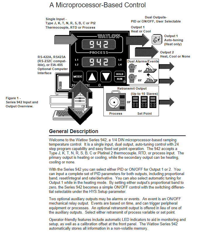
Control mode: Supports PID or ON/OFF control, can be manually selected; Dual output design, output 1 can be set as heating or cooling, and output 2 can be set as heating, cooling, or off.
Input type: compatible with J, K, T, N, R, S, B, C, Pt2 thermocouples, RTD (2-wire or 3-wire) and 0-5VDC, 4-20mA process inputs.
Programming ability: Supports 24 step program curves, including four step types: set point (StPt), constant temperature (SoAh), jump cycle (JL), and end, and can achieve multi-stage temperature control.
Auxiliary functions: optional dual auxiliary output (alarm or time triggered event), set point/process value retransmission output, supports RS-422A/RS-423A/EIA-485 communication interface.
Data storage: Non volatile memory automatically saves all parameters, and data is not lost after power failure; Lithium battery backup operation parameters, with a service life of about 10 years.
Key specifications
Temperature range: thermocouple (-328 ° F~4200 ° F/-200 ° C~2315 ° C), RTD (-328 ° F~1112 ° F/-200 ° C~600 ° C), process input (-500~3500 units).
Accuracy: ± 0.1% ± 1 LSD of full scale (ambient temperature 77 ° F ± 5 ° F, rated voltage ± 10%).
Output specifications:
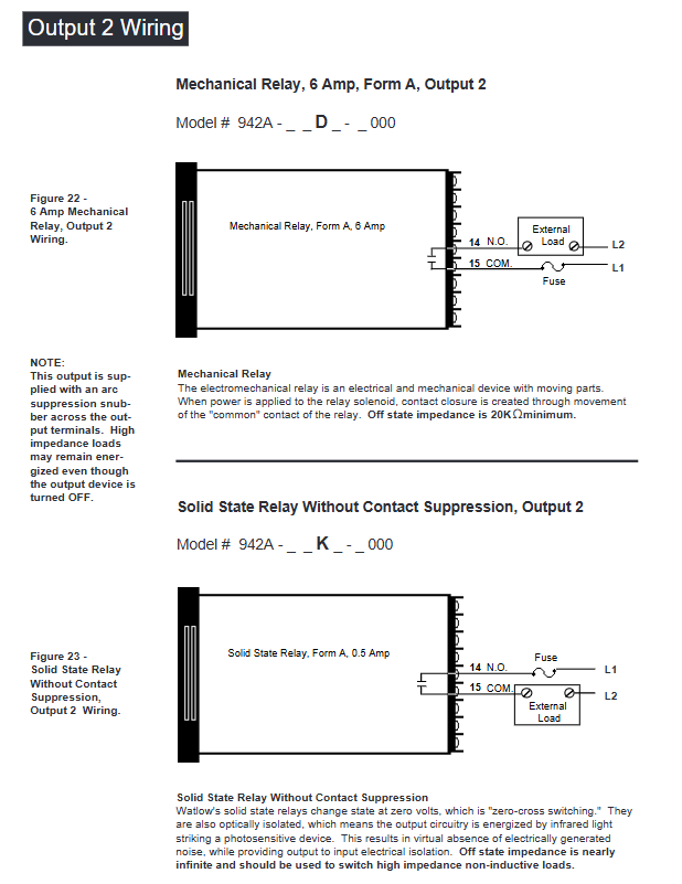
Solid state relay output: 0.5A@24-264VAC Optical isolation and zero crossing switching.
Mechanical relay output: 6A@120 /240VAC or 28VDC.
Process output: 0-5VDC/0-10VDC (minimum load 10K Ω), 4-20mA/0-20mA (maximum load 600 Ω).
Working environment: Temperature range of 32 ° F~149 ° F (0 ° C~65 ° C), humidity range of 0~90% (no condensation).
Installation and wiring process
Installation preparation
Panel Hole: Process panel holes according to size requirements (nominal 3.625 × 3.625 inches/92.08 × 92.08mm, thickness 0.06~0.25 inches/1.5~6.35mm).
Equipment fixation: Insert the controller housing into the opening, fix it from the back of the panel with the matching bracket, then insert the control chassis into the housing and lock it by rotating the front plate screw 90 ° clockwise (note that the screw should only be rotated 90 ° to avoid excessive force damage).
Wiring operation
Power wiring
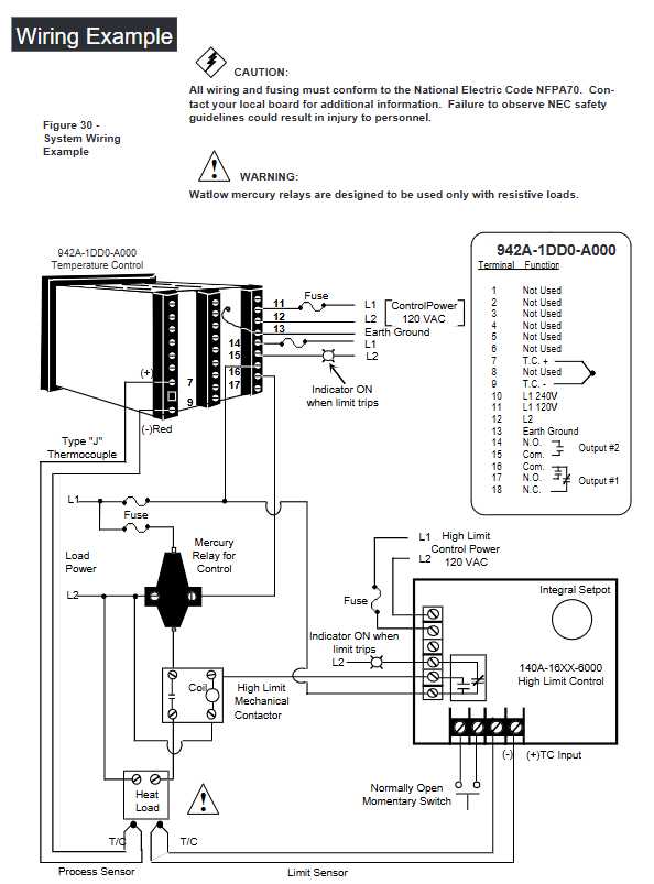
Supports 120VAC or 240VAC power supply (50/60Hz universal, no adjustment required), requires connection to L1 and L2 power terminals and grounding terminals, and wiring must comply with the National Electrical Code (NEC) to avoid the risk of electric shock.
The power supply end needs to be connected in series with a fuse. When powered by 120VAC, the L1 end needs to be connected in series with a fuse. When powered by 240VAC, both the L1 and L2 ends need to be connected in series with a fuse.
Sensor wiring
Thermocouple: Use extension cords made of the same material as the thermocouple to avoid errors; If connecting non isolated external devices, an isolated thermocouple should be selected, with positive and negative terminals corresponding to terminals 7 (+) and 9 (-).
RTD: 2-wire RTD needs to short-circuit terminals 5 and 6, and 3-wire RTD needs to ensure that the resistance of the three extension wires is consistent (with the same wire diameter and material) to compensate for lead resistance errors (every 1 Ω lead resistance of 2-wire RTD will cause an error of about+2 ° C).
Process input: 0-5VDC input is connected to terminals 1 (+) and 3 (-), with an input impedance of 100K Ω; 4-20mA input requires short circuiting terminals 2 and 3, followed by connecting the positive and negative poles of the signal, with an input impedance of 249 Ω.
Output wiring
Output 1/2: Select the wiring method according to the model (solid-state relay, mechanical relay, DC switch, process output, etc.), refer to the wiring diagram of the corresponding model in the manual for details, and ensure that the load impedance matches (such as process output 4-20mA maximum load 600 Ω).
Auxiliary output: 6 auxiliary options are available (single relay, dual relay, relay+retransmission, etc.), wired according to the corresponding terminals (24-27) of the model, and the alarm/event output is a mechanical relay( 6A@28VDC /120VAC)。
Wiring precautions
Separation of strong and weak electricity: The sensor signal line (low power) is wired separately from the power line and output line (high power), with a minimum spacing of 12 inches (305mm) to avoid cross interference; When crossing, use a 90 ° crossing.
Shielding and grounding: Shielded cables are used for low-level signal lines, and the shielding layer is only grounded at the controller end; The system is grounded at a single point to avoid grounding loops, and all grounding terminals are connected to a unified grounding body.
Parameter Configuration Guide
Enter the configuration menu
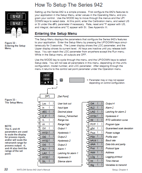
Press the UP and DOWN keys simultaneously for 3 seconds to enter the Setup menu (displaying LOC parameters); Continue holding down the UP and DOWN keys under the LOC parameter to enter the calibration menu.
During the configuration process, press the MODE key to switch parameters, use the UP/DOWN key to adjust values, and if there is no operation for 5 seconds, it will automatically save and return to the previous level, or press the MODE key to manually save and switch.
Key configuration parameters (Setup menu)
Parameter Category Core Parameter Function Description Default Values
Security and Permission LOC Operation Permission Lock (Level 0-3): Level 0 Full Permission, Level 3 Only View Setpoint/Process Values 0
Input configuration In Select input type (such as J, K, RTD, 4-20, etc.) J or r
Temperature unit (° F/° C), only displays F when input as thermocouple/RTD
The upper and lower limits of the range for the rL/rH set point/process input, as well as the default range for scaling and retransmitting the output range of the sensor
Output configuration Ot1/Ot2 output 1/2 action type (ht heating/CL cooling/no off) ht/CL
HYS1/HYS2 output 1/2 ON/OFF switching hysteresis (effective when Pb=0) 3 ° F
Alarm and event Ot3/Ot4 auxiliary output 3/4 function (AL alarm/Ent event/PrOC retransmission) AL/PrOC
AL1/AL2 alarm type (Pr process alarm/DE deviation alarm) Pr
Programming configuration PtYP program type (ti time basis/ratE ramp rate basis) ti
GSD constant temperature deviation window (program pauses when out of range) 0 (disabled)
Power outage recovery Pout program recovery method after power outage (Cont continue/HOLD hold/Abrt abort) Cont
Communication configuration: bAUD baud rate (300-9600), only models with communication function display 1200
Addr device address (0-31), only displaying 0 under FULL protocol
Operation menu parameters (Operation menu)
Setpoint (SP): Adjust the control target value within the range of rL~rH, and display OFF (disable all outputs) when it is lower than rL.
PID parameters (Pb1/Pr2, rE1/rE2, rA1/rA2): proportional band, reset/integral, rate/derivative, automatically generated after automatic tuning, or manually adjustable.
Automatic tuning (Aut): Only output 1 for heating display, select tuning rate (1 slow/2/3 fast), and the controller automatically optimizes PID parameters after startup.
Alarm setting (A1LO/A1HI, A2LO/A2HI): Process alarm setting upper and lower limits (Pr type) or deviation alarm offset (dE type).
Program Programming and Running
Fundamentals of Programming
Program structure: Up to 24 steps, each step can be selected from four types: StPt (Setpoint Slope), SoAh (Constant Temperature Holding), JL (Jump Loop), and End (Program End), supporting multiple program concatenation (a new program can start after one End step).
Programming entrance: Select Prog=YES from the Operation menu to enter the Program menu. Press the StEP parameter to select steps (1-24), and press StYP to select the step type.
Detailed explanation of four step programming methods
1. Set point step (StPt)
Core parameters:
SP: Target Set Point (rL~rH).
Time basis (PtYP=ti): HOUr/Min/SEC, total time is the sum of the three (0-23h59m59s).
Rate basis (PtYP=rAtE): rAtE, temperature change rate (0-360 ° F/min or 0-200 ° C/min).
Ent1/Ent2: On/Off status of event 1/2, displayed only when Ot3/Ot4 is set to Ent.
Example: Step 1 is set to StPt, SP=75 ° F, Min=0, SEC=1, Ent1=OFF, achieving the initial setting of reaching 75 ° F within 1 second.
2. Constant temperature step (SoAh)
Core parameters: HOUr/Min/SEC (constant temperature duration), Ent1/Ent2 (event switch), no SP parameter (inherited from the previous set point).
Example: Set Step 3 to SoAh, Min=0, SEC=25, Ent1=On, achieve 25 seconds of constant temperature and trigger Event 1.
3. Jump loop step (JL)
Core parameters:
JS: Jump to the target step (must be smaller than the current step, cannot jump to itself).
JC: Jump count (0=infinite loop, 1-100=finite loop).
Example: Set Step 6 to JL, JS=2, JC=1, implement a jump to Step 2 and repeat once (execute Steps 2-5 twice in total).
4. End step
Core parameters: End (HOLD remains in the last state/OFF closes all outputs/OFFA closes control outputs, retains alarms).
Example: Step 4 is set to End, End=OFF. After the program ends, all outputs are turned off, and 'lower' displays' OFF '.
Program Execution and Control
Start program: In the non Setup menu interface, press the HOLD/RUN button, the RUN LED flashes, select the Start Step (StP), then press the HOLD/RUN button to confirm, the RUN LED stays on, and the program starts.
Pause and Resume: Press the HOLD/RUN button once to pause (RUN LED flashes); Press the HOLD/RUN key again to switch to the rESU parameter, and press the HOLD/RUN key to resume operation (only when the program has not been modified).
View operating status: Press the MODE key to switch parameters in the RUN menu, where you can view remaining time (HOUr/Min/SEC), current rate (rAtE), event status (Ent1/Ent2), etc.
Programming Example (Slope Constant Temperature Cycle)
Requirement: Initial temperature of 75 ° F → 25 seconds to rise to 100 ° F (event 1 activated) → 25 seconds constant temperature → 25 seconds to rise to 125 ° F (event 2 activated) → 25 seconds constant temperature → jump to step 1 and repeat twice → maintain the final state.
Step by step SP (° F) Time (minutes: seconds) Ent1 Ent2 JS JC End
1 StPt 75 0:01 OFF OFF - - -
2 StPt 100 0:25 ON OFF - - -
3 SoAh - 0:25 ON OFF - - -
4 StPt 125 0:25 OFF ON - - -
5 SoAh - 0:25 ON OFF - - -
6 JL - - - - 1 2 -
7 End - - - - - - HOLd
Tuning operation (automatic and manual)
Automatic tuning (recommended)
Applicable scenario: Quickly obtain optimized PID parameters after first use and system load changes.
Operation steps:
Enter the Operation menu and find the Aut parameter (displayed only when Ot1=ht).
Press the UP/DOWN keys to select the tuning rate (1 slow/2/3 fast, mostly 2 in most scenarios).
Press the MODE key to start tuning, and the lower display alternately flashes Aut and the current parameter. During tuning, the cooling output is turned off, and the heating output runs at 90% set point ON/OFF.
Complete tuning within 80 minutes, automatically save PID parameters, restore Aut to 0, and return to normal control mode; Modifying the set point during tuning will restart tuning. Press the UP/DOWN key to set Aut=0 to abort (restore the original parameters).
Manual tuning (precise optimization)
Operation steps:
Initialization parameters: Pb1=1, Ct1=5, rE1=rA1=0, CAL=0, Aut=0, set target temperature.
Proportional band (Pb1) adjustment: gradually increase Pb1 until the process temperature stabilizes (initial reset to 0, temperature may deviate from the set point).
Reset/Integral (rE1) Adjustment: Gradually increase rE1 until the temperature begins to oscillate, then slowly decrease until the temperature stabilizes near the set point.
Rate/Differential (rA1) Adjustment: Assuming rA1=1.00 minutes, raise the set point by 20-30 ° F. If the temperature is overshoot, increase rA1 (maximum 9.99) to avoid overshoot and slow response.
Cycle time (Ct1) adjustment: Optimized within the range of 1-60 seconds. It is recommended to choose a longer cycle time for mechanical contactors (to reduce wear) and a shorter time for electronic loads (to improve control accuracy).
Alarm and fault handling
Alarm function operation
Alarm type:
Process alarm (Pr): Based on the absolute temperature threshold (A1LO/A1HI), an alarm is triggered when the temperature exceeds the range.
Deviation alarm (dE): Based on the set point offset (such as+7 ° F/-5 ° F), the alarm threshold synchronously shifts when the set point changes.
Alarm status:
Non Locked (nLA): Automatically resets after the alarm condition disappears.
Lock (LAt): Manual reset is required (first eliminate the alarm condition, then press the HOLD/RUN button).
Alarm indication: The lower display alternately flashes "LO"/"HI" and the current parameter, the L3/L4 LED lights up, and the auxiliary output triggers (N.O. closed/N.C. open).
Common faults and solutions
Fault symptoms, error codes, possible causes, and solutions
The upper display shows "----", the lower display shows Er7 Er7 A/D overflow, the sensor is open/polarity reversed, check the sensor wiring (positive and negative poles, terminal contact), confirm that the In parameter is consistent with the sensor type
The upper display shows "----", the lower display shows Er1/Er2 Er1/Er2 sensor over/under range, A/D fault confirms that the sensor range matches rL/rH, checks if the sensor is damaged, and recalibrates the A/D
Pause during program operation - gSD deviation window enabled, adjust gSD value if temperature exceeds ± gSD range (increase window), check if heating/cooling system is normal, eliminate load interference
Communication failure - baud rate/protocol/address mismatch, wiring error. Confirm that bAUd (baud rate), Prot (protocol), Addr (address) in the Setup menu are consistent with the host, and check the communication line wiring (RS-485 requires corresponding A/B lines)
Large temperature measurement error - sensor wiring error, calibration offset, environmental interference. Reconnect and confirm sensor type, enter Cal menu to adjust CAL offset, check signal line shielding and grounding
Output unresponsive - Set the set point to OFF, configure the output type incorrectly, adjust the SP to the rL~rH range for load faults, confirm the Ot1/Ot2 parameters (ht/CL), check if the load impedance matches the output type, and test if the load is normal
Calibration operation (accuracy calibration)
Calibration prerequisite
Only enter under LOC parameters and require precise equipment (such as precision millivolt source, resistance box, voltage/current source, 4.5-inch multimeter).
Backup all parameters (Setup/Operation/Program) before calibration, turn off all outputs during calibration (except for process outputs), and automatically save calibration values when the RUN LED lights up.
Core Calibration Process (Taking Thermocouples as an Example)
Wiring: Connect the precision millivolt source to terminals 7 (+) and 9 (-), connect to AC power and ground.
Preheating: Power on for 15 minutes, enter the Cal menu (hold down the UP/DOWN key under LOC parameters), press the MODE key to select the tCL parameter.
Low range calibration: The millivolt source outputs 0.00mV, and after stabilizing for 10 seconds, press the MODE button.
High range calibration: J-type thermocouple outputs 50.00mV, R/S/B type outputs 16.035mV. After stabilizing for 10 seconds, press the MODE button.
Compensation calibration: Disconnect the millivolt source and connect the J-type reference compensator (32 ° F/0 ° C). After stabilizing for 10 seconds, press the HOLD/RUN button to exit the RUN mode and complete the calibration.
Other calibrations (RTD/process input/output)
RTD calibration: Use a 1K Ω precision resistance box to connect terminals 4-6, and input low/high resistance values according to the rLO/rHI parameters (refer to Table 7 in the manual).
4-20mA input calibration: Short circuit terminals 2-3, output 4.00mA (4A parameter) and 20.00mA (20A parameter) from the current source, and calibrate sequentially.
Process output calibration: Connect a multimeter and a matching resistor (such as 4-20mA connected to a 470 Ω resistor), adjust the output to the target value (such as 4.00mA/20.00mA) according to the O1LO/O1HI parameters.
Maintenance and Precautions
routine maintenance
Regular inspection: Check whether the sensor wiring is loose or corroded, whether the panel screws are tightened, and whether the heat dissipation is good.
Battery replacement: Lithium batteries (with backup operating parameters) have a lifespan of about 10 years. In case of abnormal Pout or Run parameters, they need to be returned to the factory for replacement.
Cleaning and maintenance: Wipe the panel with a dry soft cloth to prevent liquid from seeping into the interior of the equipment; Avoid using in damp, dusty, and corrosive environments.
Safety precautions
Disconnect the power supply before wiring, strictly follow NEC and local electrical regulations, and ensure reliable grounding (to avoid electric shock and interference).
The front plate screws should only be rotated 90 °, and excessive force should be avoided to avoid damaging the chassis locking structure.
Mercury relays are only suitable for resistive loads and are prohibited from being used for inductive loads (such as motors without buffering).
Calibration and maintenance must be carried out by professional personnel, and unauthorized disassembly of the equipment casing is prohibited (which may affect warranty).
- OMRON
- ABB
- General Electric
- EMERSON
- Honeywell
- HIMA
- ALSTOM
- Rolls-Royce
- MOTOROLA
- Rockwell
- Siemens
- Woodward
- YOKOGAWA
- FOXBORO
- KOLLMORGEN
- MOOG
- KB
- YAMAHA
- BENDER
- TEKTRONIX
- Westinghouse
- AMAT
- AB
- XYCOM
- Yaskawa
- B&R
- Schneider
- KONGSBERG
- NI
- WATLOW
- ProSoft
- SEW
- ADVANCED
- Reliance
- TRICONEX
- METSO
- MAN
- Advantest
- STUDER
- DANAHER MOTION
- Bently
- Galil
- EATON
- MOLEX
- DEIF
- B&W
- ZYGO
- Aerotech
- DANFOSS
- Beijer
- Moxa
- Rexroth
- Johnson
- WAGO
- TOSHIBA
- BMCM
- SMC
- HITACHI
- HIRSCHMANN
- Application field
- XP POWER
- CTI
- TRICON
- STOBER
- Thinklogical
- Horner Automation
- Meggitt
- Fanuc
- Baldor
- SHINKAWA
- Other Brands
- UniOP
- KUKA
- Iba
- Beckhoff
-
 Basler Electric DECS-200-1L Digital Excitation Control System
 -
 Basler DECS125-15-B2C1 Excitation Control
 -
 Basler 9507900205 SSR Retrofit Voltage Regulator
 -
 Basler BE2000E Digital Voltage Regulator
 -
 Basler BE1-GPS Generator Protection System
 -
 Basler DECS-250-CN1CN1N Digital Excitation Control
 -
 Basler DGC-2020 Genset Controller
 -
 Basler BE1-81O UT3ED1LA7N0F Frequency Relay (Variant)
 -
 Basler BE1-81O UT3EE1YA9S0F Frequency Relay (Variant)
 -
 Basler BE1-81O Over/Under Frequency Relay
 -
 Basler DECS125-15 Digital Excitation Control
 -
 Basler Electric BE1-951 Overcurrent Protection System
 -
 Basler Electric BE1-700V Digital Protective Relay
 -
 Basler Electric APR63-5 Automatic Voltage Regulator
 -
 Basler Electric BE1-851 Overcurrent Protection System
 -
 Basler Electric DECS-250-LN1SN1N Excitation Control
 -
 Basler Electric BE1-87T Transformer Differential Relay
 -
 Basler Electric DECS-200-1L Excitation Control System
 -
 Basler Electric 9310300100 DECS-300 Excitation Control
 -
 Basler Electric SSE-N 125-4.5KW Shunt Exciter Regulator
 -
 Basler Electric DGC-2020HD-5NS1DNSBA Genset Controller
 -
Basler Electric BE1-81-O/UT3EE1JB7N1F Frequency Relay
-
 Basler Electric BE1-81T1EE1WA0N1F Frequency Relay
 -
 Basler Electric BE1-25M1EA6PN5R1F Sync-Check Relay
 -
 Basler Electric BE1-GPS Generator Protection System
 -
Basler Electric DECS-250-LN1SN1N Excitation Control Rev V
-
 Basler Electric DECS-250-CN2CN1N Excitation Control
 -
 Basler Electric BE1-50/51B-207 Overcurrent Relay
 -
Basler Electric DECS-300-C0N0 Excitation Control System
-
Basler Electric DECS-200 Digital Excitation Control System
-
Basler Electric DECS-250-LN1CN1N Excitation Unit
-
Basler Electric DECS-250 LN2SA1D Excitation Unit Specs
-
Basler Electric BE1-87T Transformer Relay Review
-
Basler Electric BE1-11 Protection System
-
Basler Electric BE1-GPS100-E4N1H1N Protection System
-
 Allen-Bradley 442G-MABH-R Safety Module
 -
 Beckhoff CX1030-0111 PLC Assembly Profile
 -
 FANUC IC693CPU364 PLC Module
 -
 Orange Denmark Type 200816 220 PLC Specs
 -
 OMRON C200H-SNT31 Sysmac PLC Module
 -
 Allen Bradley 20AB022A3AYNANC0 PowerFlex 70
 -
 OMRON C200HW-PCU01 Position Control Unit
 -
 ABB AO845A-eA Analog Output Module
 -
 OMRON CJ1M-CPU22 CPU Unit
 -
 Allen Bradley 100-E265ED11 Contactor
 -
 Honeywell 51304511-100 Interface Module
 -
 SOLEXY BXF3S0101N0018 Gateway Module
 -
 OMRON CJ2H-CPU65 CPU Unit
 -
 Automation Direct GS2-45P0 AC Drive
 -
 M68-2000 2-Axis Motion CNC Controller
 -
 OMRON CJ1M-CPU11 V3.0 PLC CPU Unit
 -
 OMRON CJ1W-NC413 4-Axis Positioning Controller
 -
 OMRON 3G2A3-PRO16 Programming Console HMI
 -
 Siemens 3VT8440-2AA04-2GA2 Molded Case Circuit Breaker
 -
 Siemens 3RT5045 Contactor Series
 -
 OMRON C200HS-CPU01-E SYSMAC PLC Controller
 -
 OMRON C500-NC103-E Positioning Control Unit
 -
 OMRON CJ1W-TC001 Temperature Control Unit
 -
 OMRON NJ301-1100 NJ-PA3001 PLC System EtherCAT
 -
 Pilz 773100 M1P Safety Relay Base Unit
 -
 Siemens SINUMERIK 840D SL NCU 720.3B with PLC 317-3 PN/DP
 -
 Siemens 6AV6618-7GD01-3AB0 HMI Panel
 -
 OMRON F150-C15E-3 Vision Mate Controller PLC Overview
 -
 Mitsubishi MELSEC A Series PLC System A63P A3ACPU A616AD A68RD3
 -
 M68-2000 2 Axis Motion Controller SCE SERVO CNC
 -
 OMRON FZ-S2M PLC Camera Vision System
 -
 VISOLUX SLVA-4K PLC Module from Elektronik GmbH
 -
 OMRON CJ1M-CPU23 V2.0 PLC CPU Unit
 -
 ABB AI86-16CHF PCB Card 5761751-9 B Specifications
 -
 Allen-Bradley 100-D140ZJ22L Contactor Overview
 -
 Merlin Gerin PB80 PLC Rack
 -
 WEIR WE203 Power Supply PLC
 -
 OMRON NX-TS3102 Temperature Input Unit
 -
 Siemens 6ES7146-6FF00-0AB0 I/O Module
 -
 Fanuc A16B-3300-0057 Circuit Board
 -
 OMRON CJ1W-IDP01 Input Module
 -
 Siemens 6FX2007-1AD13 Handheld Unit
 -
 Gems EM54 PLC Module PCB
 -
 Beckhoff CX2030-0121 Embedded PC CPU
 -
 OMRON NJ301-1100 Machine Automation Controller
 -
 Biesse Rover CNI PLC 2153 030 7146.30 Numerical Control Module
 -
 OMRON CJ1W DA08V Analog Output Module
 -
 OMRON CS1D ETN21D Ethernet Module
 -
 Allen Bradley 1768 L43 CompactLogix Controller
 -
 Schneider TWDLMDA40DTK Twido PLC Module
 -
 Mitsubishi NZ2EX2B 60AD4 Analog Input Module
 -
 OMRON NS8 TV00B V2 Touch Display Panel
 -
 Mitsubishi AY71 CMOS TTL Output Module
 -
 OMRON C500 CPU11 E Processor Module
 -
 OMRON CJ1W PTS51 Temperature Input Module
 -
 Siemens 6SL3100-1DE22-0AA1 600V DC Supply
 -
 OMRON CJ1M-CPU23 PLC CPU 9‑Pin Serial
 -
 Schlumberger IMT4N 24‑250VAC 48‑230VAC PLC Timer
 -
 OMRON CJ1M-CPU22 PLC CPU Unit V2.0
 -
 Allen‑Bradley 2711P-B7C6D2 Touch Screen PanelView
 -
 ADSP-2181KST-160 Analog Devices DSP IC Specs
 -
 Schneider LC1F400 400A Contactor Specifications
 -
 Yaskawa SGDH-10DE-OY 1kW 400V Servo Drive
 -
 Schneider TM262L10MESE8T M262 PLC 5ns Inst
 -
 Mitsubishi AA104VJ05 10.4in LCD Panel Specs
 -
 Allen Bradley 1761-L32BWA MicroLogix 1000 PLC
 -
 Siemens 6ES7431-7KF00-0AB0 Analog Input Module
 -
 Allen Bradley 1769-OB16 Output Module
 -
 Siemens 6ES7131-1BL12-0XB0 Input Module
 -
 Beckhoff EP7041-3002 EtherCAT Box Module
 -
 Siemens RK7243-2AA30-0XB0 Communication Module
 -
 Siemens 4AM5742-8DD40-0FA0 Transformer
 -
 Siemens 3TK2834-1BB40 Safety Relay
 -
 Brother BAS 311 Sewing Machine Circuit Board
 -
Yaskawa SGDH-10DE-OY Servo Driver
-
 OMRON C60H C6DR DE V1 Sysmac PLC
 -
 MITSUBISHI ELECTRIC A2ACPU21 S1 CPU Module
 -
 ABB BAILEY INNPM12 Network Process Module
 -
 HONEYWELL 620 0073C IPC PLC Module
 -
 Mitsubishi 15050 PR02B PLC Circuit Board
 -
 SIEMENS 6SY7000 0AC37 Drive Control Module
 -
 OMRON TJ2 ECT16 Traxial EtherCAT Controller
 -
 GE Fanuc IC698PSD300D Power Supply Module
 -
 Texas Instruments Series 505 16 Position Base
 -
 OMRON YASKAWA SGDH 10DE OY Servo Drive
 -
 Allen‑Bradley 440G-MT Safety Interlock Switch Specs
 -
 Rubycon PD27A 24V 8A Power Supply Module
 -
 SK-H1-GDB1-F11D PLC Gate Driver Board Kit
 -
 VIPA 441-4UA14 451-4UA14 PLC Module Rack
 -
 Mitsubishi FX5U-80MT ESS PLC Controller Specs
 -
 Mitsubishi Q64TCRTN Temperature PLC Module
 -
 GE 1C31170G Rev10 PLC Circuit Board Module
 -
 Schneider TWDLMDA40DTK PLC Controller Module


