
Watlow Series 988 Controller
Watlow Series 988 Controller
The Watlow Series 988 controller is a 1/8 DIN microprocessor based temperature/process controller that integrates multiple functions, covering four models: 986, 987, 988, and 989. It has flexible configuration, compact size, and high durability, and can adapt to various temperature and process control scenarios. It supports multiple input/output options and complex control algorithms.
Core characteristics of controller
1. Hardware and functional highlights
Compact design: 1/8 DIN size, integrated with rich functions, balancing flexibility and durability
Control capability: Supports single unit cascade control, covering various process variables such as temperature, pressure, flow rate, etc
Featured features: including heater current monitoring, remote setpoint input, proportional control, and sliding line feedback valve control
Algorithm and Alarm: Equipped with extended self-tuning function, enhanced alarm function, and multiple unique control algorithms
2. Model coverage
When referring to "Series 988", it includes both horizontal and low-voltage versions (986, 987, 988, 989)
There are differences in power specifications and installation methods among different models (such as 986/988 for vertical installation and 987/989 for horizontal installation)

Installation and hardware settings
1. DIP switch configuration
Number of switches: Depending on the model, the controller contains 1-6 DIP switches inside
Core functions: Configure input sensor types, provide power for external signal conditioners, lock some functions of the front panel
Operation steps: Press the release tabs on both sides/top of the panel to remove the controller chassis. After setting the switch as shown in the diagram, reset the chassis and ensure that all four tabs are securely fastened
2. Panel installation
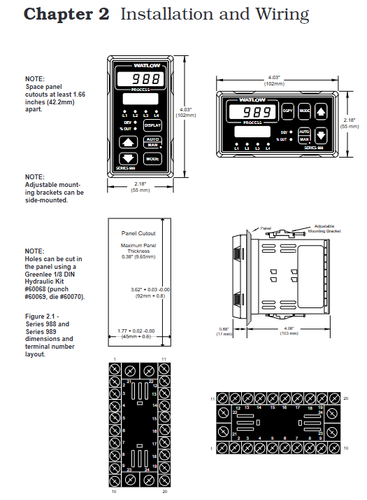
Installation preparation: Contact the back of the panel and cut the panel cut according to the size requirements (recommended to use Greenlee 1/8 DIN hydraulic kit)
Installation steps: Slide the controller housing into the panel cut, ensure that the sealing gasket is flat, install the bracket and tighten the screws (to avoid deformation of the housing due to over tightening), and finally insert the chassis and clamp it tightly
Sealing requirements: Strictly follow the installation process to ensure NEMA 4X sealing level and prevent equipment damage
3. Wiring specifications
Safety prerequisite: Follow the National Electrical Code (NEC) safety standards to avoid the risk of electric shock
Core wiring: including power wiring (100-240V AC/DC or 24-28V AC/DC), sensor wiring (thermocouples, RTDs, etc.), input/output wiring (supporting up to 4 inputs and 4 outputs)
Isolation requirement: Optical isolation (500V AC isolation barrier) is used between analog input and controller output/digital input to avoid grounding loops
Operation interface and menu navigation
1. Front panel buttons and display
Core keys: Up arrow key (increase value), Down arrow key (decrease value), Mode key (confirm/switch menu), Display key (return to display loop), Auto/Manual key (mode switch/alarm reset)
Display function: upper displays actual process values, parameter values, or error codes; Lower displays set points, deviations, percentage outputs, etc; L1-L4 LED indicates whether the corresponding output is activated
Special operation: Press the up and down arrow keys simultaneously for 3 seconds to enter the settings menu, and press again for 3 seconds to enter the factory menu (which can be locked through DIP switch)
2. Core menu system
(1) Display Loop
Definition: The controller defaults to the "home" state and automatically returns after 1 minute of inactivity. Pressing the display button can return at any time
Display content: including input 1 reading, set point 1, input 2 reading (if equipped), deviation value, percentage output, temperature unit, etc
(2) Setup menus
Entry method: In the display loop state, press the up and down arrow keys simultaneously for 3 seconds
Includes menus: Input menu (InPt), Output menu (OtPt), Global menu (GLbL), Communication menu (COM, visible only for models equipped with communication function)
Operation rules: Output disabled during menu navigation. Use the up and down arrow keys to select the menu, and the mode key to step through the menu options
(3) Operation menus
Entry method: Press the mode key while displaying the loop state
Includes menus: System Menu (SYS), PID A Menu (PidA), PID B Menu (Pidb)
Core functions: Set second set point, idle set point, alarm trigger value, start self-tuning, etc
(4) Factory menus
Entry method: In the settings menu state, continue pressing the up and down arrow keys for 3 seconds
Includes menus: Panel Lock Menu (PLOC), Diagnostic Menu (diAg), Calibration Menu (CAL)
Restriction: When the hardware lock DIP switch is turned on, the menu cannot be accessed
Core functional configuration
1. Input/output configuration
Input settings: Select sensor type (thermocouple, RTD, 4-20mA, etc.), set decimal places, range upper and lower limits, calibration offset
Output settings: Configure output response mode (heating/cooling, alarm activation/deactivation), set lag value, alarm type (process alarm, deviation alarm, rate alarm)
- OMRON
- ABB
- General Electric
- EMERSON
- Honeywell
- HIMA
- ALSTOM
- Rolls-Royce
- MOTOROLA
- Rockwell
- Siemens
- Woodward
- YOKOGAWA
- FOXBORO
- KOLLMORGEN
- MOOG
- KB
- YAMAHA
- BENDER
- TEKTRONIX
- Westinghouse
- AMAT
- AB
- XYCOM
- Yaskawa
- B&R
- Schneider
- KONGSBERG
- NI
- WATLOW
- ProSoft
- SEW
- ADVANCED
- Reliance
- TRICONEX
- METSO
- MAN
- Advantest
- STUDER
- DANAHER MOTION
- Bently
- Galil
- EATON
- MOLEX
- DEIF
- B&W
- ZYGO
- Aerotech
- DANFOSS
- Beijer
- Moxa
- Rexroth
- Johnson
- WAGO
- TOSHIBA
- BMCM
- SMC
- HITACHI
- HIRSCHMANN
- Application field
- XP POWER
- CTI
- TRICON
- STOBER
- Thinklogical
- Horner Automation
- Meggitt
- Fanuc
- Baldor
- SHINKAWA
- Other Brands
- UniOP
- KUKA
- Iba
- Beckhoff
-
 Basler BE1-700V Digital Protective Relay
 -
 Basler BE1-951 Overcurrent Protection System
 -
 Basler DECS-300 Digital Excitation Control
 -
 Basler DECS-200 Digital Excitation Control
 -
 Basler DECS-200-1C Excitation Control System
 -
Basler DECS-200-1L Digital Excitation Control
-
 Basler Electric BE1-GPS Generator Protection System
 -
Basler Electric DECS-200-1C Digital Excitation Controller
-
 Basler Electric DECS125-15 Excitation Control with Power Module
 -
 Basler Electric BE1-87G Differential Relay
 -
 Basler Electric BE1-11 Protection System I5A3M2P2N0EA00
 -
Basler Electric DECS-200-1C Excitation Control System
-
Basler Electric BE1-11g Generator Protection Relay
-
 Basler Electric DECS 125-15-B2C1 V2.0.9 Excitation Control
 -
 Basler Electric BE1-81O/UT3ED1JA7N2F Frequency Relay
 -
 Basler Electric BE1-81O/UT3EE1YB7N1F Frequency Relay
 -
 Basler Electric DECS-200-1L Digital Excitation Control System
 -
 Basler DECS125-15-B2C1 Excitation Control
 -
 Basler 9507900205 SSR Retrofit Voltage Regulator
 -
 Basler BE2000E Digital Voltage Regulator
 -
 Basler BE1-GPS Generator Protection System
 -
 Basler DECS-250-CN1CN1N Digital Excitation Control
 -
 Basler DGC-2020 Genset Controller
 -
 Basler BE1-81O UT3ED1LA7N0F Frequency Relay (Variant)
 -
 Basler BE1-81O UT3EE1YA9S0F Frequency Relay (Variant)
 -
Basler BE1-81O Over/Under Frequency Relay
-
Basler DECS125-15 Digital Excitation Control
-
Basler Electric BE1-951 Overcurrent Protection System
-
 Basler Electric BE1-700V Digital Protective Relay
 -
 Basler Electric APR63-5 Automatic Voltage Regulator
 -
Basler Electric BE1-851 Overcurrent Protection System
-
Basler Electric DECS-250-LN1SN1N Excitation Control
-
 Basler Electric BE1-87T Transformer Differential Relay
 -
 Basler Electric DECS-200-1L Excitation Control System
 -
 Basler Electric 9310300100 DECS-300 Excitation Control
 -
 Basler Electric SSE-N 125-4.5KW Shunt Exciter Regulator
 -
 Basler Electric DGC-2020HD-5NS1DNSBA Genset Controller
 -
Basler Electric BE1-81-O/UT3EE1JB7N1F Frequency Relay
-
Basler Electric BE1-81T1EE1WA0N1F Frequency Relay
-
 Basler Electric BE1-25M1EA6PN5R1F Sync-Check Relay
 -
 Basler Electric BE1-GPS Generator Protection System
 -
Basler Electric DECS-250-LN1SN1N Excitation Control Rev V
-
 Basler Electric DECS-250-CN2CN1N Excitation Control
 -
 Basler Electric BE1-50/51B-207 Overcurrent Relay
 -
Basler Electric DECS-300-C0N0 Excitation Control System
-
Basler Electric DECS-200 Digital Excitation Control System
-
Basler Electric DECS-250-LN1CN1N Excitation Unit
-
Basler Electric DECS-250 LN2SA1D Excitation Unit Specs
-
Basler Electric BE1-87T Transformer Relay Review
-
Basler Electric BE1-11 Protection System
-
Basler Electric BE1-GPS100-E4N1H1N Protection System
-
 Allen-Bradley 442G-MABH-R Safety Module
 -
 Beckhoff CX1030-0111 PLC Assembly Profile
 -
 FANUC IC693CPU364 PLC Module
 -
 Orange Denmark Type 200816 220 PLC Specs
 -
 OMRON C200H-SNT31 Sysmac PLC Module
 -
 Allen Bradley 20AB022A3AYNANC0 PowerFlex 70
 -
 OMRON C200HW-PCU01 Position Control Unit
 -
 ABB AO845A-eA Analog Output Module
 -
 OMRON CJ1M-CPU22 CPU Unit
 -
 Allen Bradley 100-E265ED11 Contactor
 -
 Honeywell 51304511-100 Interface Module
 -
 SOLEXY BXF3S0101N0018 Gateway Module
 -
 OMRON CJ2H-CPU65 CPU Unit
 -
 Automation Direct GS2-45P0 AC Drive
 -
 M68-2000 2-Axis Motion CNC Controller
 -
 OMRON CJ1M-CPU11 V3.0 PLC CPU Unit
 -
 OMRON CJ1W-NC413 4-Axis Positioning Controller
 -
 OMRON 3G2A3-PRO16 Programming Console HMI
 -
 Siemens 3VT8440-2AA04-2GA2 Molded Case Circuit Breaker
 -
 Siemens 3RT5045 Contactor Series
 -
 OMRON C200HS-CPU01-E SYSMAC PLC Controller
 -
 OMRON C500-NC103-E Positioning Control Unit
 -
 OMRON CJ1W-TC001 Temperature Control Unit
 -
 OMRON NJ301-1100 NJ-PA3001 PLC System EtherCAT
 -
 Pilz 773100 M1P Safety Relay Base Unit
 -
 Siemens SINUMERIK 840D SL NCU 720.3B with PLC 317-3 PN/DP
 -
 Siemens 6AV6618-7GD01-3AB0 HMI Panel
 -
 OMRON F150-C15E-3 Vision Mate Controller PLC Overview
 -
 Mitsubishi MELSEC A Series PLC System A63P A3ACPU A616AD A68RD3
 -
 M68-2000 2 Axis Motion Controller SCE SERVO CNC
 -
 OMRON FZ-S2M PLC Camera Vision System
 -
 VISOLUX SLVA-4K PLC Module from Elektronik GmbH
 -
 OMRON CJ1M-CPU23 V2.0 PLC CPU Unit
 -
 ABB AI86-16CHF PCB Card 5761751-9 B Specifications
 -
 Allen-Bradley 100-D140ZJ22L Contactor Overview
 -
 Merlin Gerin PB80 PLC Rack
 -
 WEIR WE203 Power Supply PLC
 -
 OMRON NX-TS3102 Temperature Input Unit
 -
 Siemens 6ES7146-6FF00-0AB0 I/O Module
 -
 Fanuc A16B-3300-0057 Circuit Board
 -
 OMRON CJ1W-IDP01 Input Module
 -
 Siemens 6FX2007-1AD13 Handheld Unit
 -
 Gems EM54 PLC Module PCB
 -
 Beckhoff CX2030-0121 Embedded PC CPU
 -
 OMRON NJ301-1100 Machine Automation Controller
 -
 Biesse Rover CNI PLC 2153 030 7146.30 Numerical Control Module
 -
 OMRON CJ1W DA08V Analog Output Module
 -
 OMRON CS1D ETN21D Ethernet Module
 -
 Allen Bradley 1768 L43 CompactLogix Controller
 -
 Schneider TWDLMDA40DTK Twido PLC Module
 -
 Mitsubishi NZ2EX2B 60AD4 Analog Input Module
 -
 OMRON NS8 TV00B V2 Touch Display Panel
 -
 Mitsubishi AY71 CMOS TTL Output Module
 -
 OMRON C500 CPU11 E Processor Module
 -
 OMRON CJ1W PTS51 Temperature Input Module
 -
 Siemens 6SL3100-1DE22-0AA1 600V DC Supply
 -
 OMRON CJ1M-CPU23 PLC CPU 9‑Pin Serial
 -
 Schlumberger IMT4N 24‑250VAC 48‑230VAC PLC Timer
 -
 OMRON CJ1M-CPU22 PLC CPU Unit V2.0
 -
 Allen‑Bradley 2711P-B7C6D2 Touch Screen PanelView
 -
 ADSP-2181KST-160 Analog Devices DSP IC Specs
 -
 Schneider LC1F400 400A Contactor Specifications
 -
 Yaskawa SGDH-10DE-OY 1kW 400V Servo Drive
 -
 Schneider TM262L10MESE8T M262 PLC 5ns Inst
 -
 Mitsubishi AA104VJ05 10.4in LCD Panel Specs
 -
 Allen Bradley 1761-L32BWA MicroLogix 1000 PLC
 -
 Siemens 6ES7431-7KF00-0AB0 Analog Input Module
 -
 Allen Bradley 1769-OB16 Output Module
 -
 Siemens 6ES7131-1BL12-0XB0 Input Module
 -
 Beckhoff EP7041-3002 EtherCAT Box Module
 -
 Siemens RK7243-2AA30-0XB0 Communication Module
 -
 Siemens 4AM5742-8DD40-0FA0 Transformer
 -
 Siemens 3TK2834-1BB40 Safety Relay
 -
 Brother BAS 311 Sewing Machine Circuit Board
 -
Yaskawa SGDH-10DE-OY Servo Driver
-
 OMRON C60H C6DR DE V1 Sysmac PLC
 -
 MITSUBISHI ELECTRIC A2ACPU21 S1 CPU Module


