
Watlow Series L Temperature Limiting Controller
Watlow Series L Temperature Limiting Controller
Product series and core positioning
1. Product series division and applicable scenarios
The Watlow Series L series is divided into three sub series: LF, LV, and LS, all of which are industrial grade temperature limit controllers. Its core function is to serve as a redundant safety device for the main control system, independently monitoring temperature and triggering protective actions to prevent equipment damage, product scrapping, or personnel injury caused by thermal runaway. The differences in adaptation scenarios are as follows:
Series Core Features Operating Interface Setpoint Types Applicable Scenarios
The LF series has no operating interface, low cost, no display screen, and no operation keys to fix the set point (customizable at the time of ordering and cannot be modified on site). It does not require on-site adjustment of the set point in scenarios such as standardized production lines and fixed temperature protection for enclosed equipment (such as protection for the heating section of plastic extruders)
The LV series comes with an operation interface that supports on-site adjustment of 4-digit 7-segment LED display screens (displaying set points), ° F/° C indicator lights, ALARM indicator lights, and adjustable set points through rotary encoders/buttons (supporting on-site modification, with "press setting" to prevent misoperation). Scenes that require frequent adjustment of set points, such as food processing equipment (baking ovens, sterilizers), and small laboratory equipment
LS series safety level design, redundant protection only LED status indicator light (no set point display), fixed set point (customizable at the time of ordering, cannot be modified on site), high safety demand scenarios, such as heating equipment that may cause fires (industrial ovens, painting production lines), medical equipment auxiliary heating protection
2. Core values and differentiation advantages
Independent safety protection: completely independent from the main controller, equipped with sensors, power circuits, and output actuators. Even if the main controller fails (such as sensor failure or output adhesion), it can still reliably trigger protection and avoid the risk of "single point failure".
Multi installation adaptation: Supports 1/8 DIN panel installation, DIN rail installation, open circuit board installation, and encapsulation module installation, covering various installation needs from standardized cabinets to customized equipment.
Complete authoritative certifications: The entire series has passed UL 873 (temperature regulator), CSA C22.2 # 24 (temperature control), and FM Class 3545 (temperature limit switch) certifications; The LS series additionally complies with UL/EN 60730-1/2-9 (automatic control for household and similar equipment), suitable for harsh scenarios such as food service and medical assistance.
Wide compatibility of sensors: Supports thermocouples (E/J/K/T type) and RTDs (100 Ω platinum resistors), adapting to different temperature ranges and accuracy requirements, such as K-type thermocouples for high-temperature industrial furnaces (-270~1370 ° C) and T-type thermocouples for low-temperature refrigeration equipment (-270~400 ° C).
Product basic specifications
1. Physical and installation specifications
(1) Installation method and size
Installation type size (width x height x depth) Installation requirements Protection level
1/8 DIN panel installation 72.4mm × 72.4mm × 51.7mm (depth behind the panel) panel opening 72.4mm × 72.4mm, thickness 1.52-3.18mm, requires the use of a matching installation bracket to lock the foundation IP20; Optional NEMA 4X/IP65 with buttons (splash proof, dustproof)
DIN rail installation 78.1mm × 112.3mm × 90.7mm (including rail depth 94.7mm) compatible with 35mm × 7.5mm standard DIN rail (DIN 50022), fixed with a snap on structure IP10 (only prevents solid foreign objects)
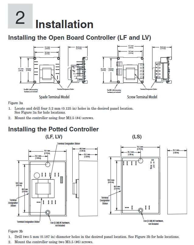
Installation of an open circuit board with dimensions of 61.7mm × 61.7mm × 45.1mm requires drilling four 3.2mm installation holes, which should be fixed using M2.5 (# 4) screws without protection (to be installed in a closed cabinet)
The installation of the sealing module requires drilling two 5mm installation holes of 70.1mm × 102.9mm × 46.6mm, and fixing them with M3.5 (# 6) screws to IP65 (corrosion-resistant, splash proof, suitable for humid/dusty environments)
(2) Terminal specifications
Terminal type: Two types of terminals can be selected, specify when ordering:
Quick connect terminals: 6.3mm spacing, compatible with AMP P/N 3-520406-2 (terminals 1/2/6-10) and AMP P/N 2-520405-2 (terminals 3-5), requiring AMP 58078-3 crimping tool.
Removable screw terminal: Supports 12-30 AWG wires, with a stripping length of 8mm and a maximum terminal torque of 0.8 Nm (7 in lb) to avoid damage to the terminal due to over tightening.
Wiring identification: Terminal function labels are affixed on the back, clearly indicating terminal definitions such as power supply (L1/L2), sensor (TC+/TC -, RTD S1/S2/S3), output (COM/NO/NC), reset (RESET), etc.
2. Power supply and environmental adaptability
(1) Power supply parameters
Series power supply voltage range, frequency, power consumption, power-off data storage
LF/LV 24V AC(+10%/-15%)、120V AC(+10%/-15%)、230-240V AC(+10%/-15%) 50/60Hz ± 5% maximum 10VA non-volatile memory (parameters not lost)
LS 100-240V AC (+10%/-15%) 50/60Hz ± 5% maximum 10VA non-volatile memory
(2) Environmental parameters
Working environment: Temperature 0-70 ° C (32-158 ° F), relative humidity 0-90% RH (non condensing), avoid direct contact of condensed water with equipment.
Storage environment: Temperature -40-85 ° C (-40-185 ° F), relative humidity 0-95% RH (non condensing).
Anti interference capability: Complies with EN 61326-1 standard, industrial environment anti electromagnetic interference (EMI), sensor cables are recommended to use shielded wires (only grounded at the sensor end), away from high-voltage power lines (spacing ≥ 10cm).
3. Sensor and input specifications
(1) Thermocouple input
Thermocouple Type Range (Example) Accuracy Key Requirements
E-type -200-800 ° C (-328-1470 ° F) ± 1% range ± 1 ° C (standard conditions 25 ° C ± 3 ° C) needs to distinguish between positive and negative poles (red is negative), and extension requires the same type of compensating wire to avoid errors caused by copper wires
J-type 0-750 ° C (32-1382 ° F); LS series: -18-406 ° C (0-763 ° F) ± 1% range ± 1 ° C Suitable for medium and low temperature scenarios, low cost, good oxidation resistance
K-type -270-1370 ° C (-328-2282 ° F); LS series: -18-537 ° C (0-999 ° F) ± 1% range ± 1 ° C Suitable for high temperature scenarios, good stability, widely used in industrial furnaces and kilns
T-type -200-350 ° C (-328-662 ° F) ± 2.4% range (-200-0 ° C), ± 1% range (0-350 ° C) suitable for low temperature scenarios (such as refrigeration equipment), resistant to humidity corrosion
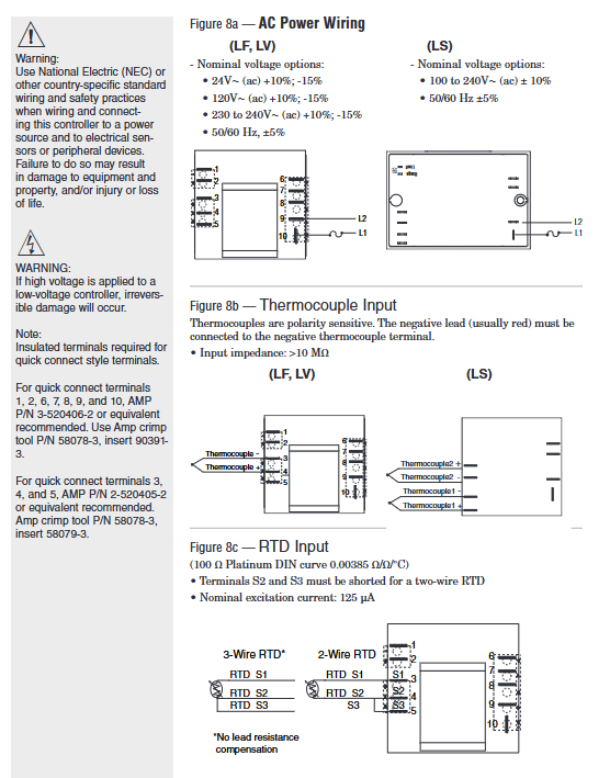
Input impedance:>10M Ω, to avoid errors caused by external circuit shunting; Cold end compensation: Built in electronic cold end compensation with an accuracy of ± 0.1 ° C, without the need for additional compensation wires.
(2) RTD input (only supported by LF/LV)
Type: 100 Ω platinum resistor, in accordance with DIN 0.00385 temperature coefficient curve.
Range: -200-800 ° C (-328-1472 ° F).
Wiring method:
3-wire system: S1 (signal+), S2 (signal -), S3 (compensation), automatically compensates for wire resistance.
2-wire system: S2 and S3 terminals need to be short circuited. For every 1 Ω increase in wire resistance, the measurement error increases by 2.6 ° C (4.7 ° F). It is recommended that the wire length be ≤ 10 meters.
Excitation current: 125 µ A (nominal), to avoid excessive current causing RTD self heating error.
4. Output and protection specifications
(1) Output type and parameters
Series output types, rated parameters, applicable load life
LF/LV Form C mechanical relay (single pole double throw) 8A/240V AC (resistive load), 250VA (inductive load, 120/240V AC), 30V DC (maximum) contactor coil, solenoid valve, alarm light, etc. Inductive load requires parallel RC suppressor (Watlow P/N 08040147-0000) 100000 cycles (at rated current)
LS Form A mechanical relay (single pole single throw) 8A/240V AC (resistive load), 120VA (inductive load, 120/240V AC) is only used to cut off high-risk loads (such as heating tube power supply), without the need for RC suppressors for 6000 cycles (at rated current)
Output logic: Under normal conditions, the NO (normally open) contact of LF/LV is closed and the NC (normally closed) contact is open; After triggering the restriction condition, the output is locked, the NO contact is disconnected, and the NC contact is closed (cutting off the load power or triggering an alarm).
(2) Protection function
Temperature limit:
High temperature limit (full series): Protection is triggered when the temperature exceeds the set point.
Low temperature limit (LF/LV only): Protection is triggered when the temperature is below the set point (such as freezing of refrigeration equipment).
Sensor fault protection:
Sensor open circuit: triggers output lockout, displays fault code [Er; In] (only LV is displayed).
Sensor short circuit: When the thermocouple is short circuited, the ambient temperature is displayed, and when the RTD is short circuited, the low range value is displayed, both triggering protection.
LS series additional protection:
Dual sensor deviation monitoring: When the temperature difference between the two sensors exceeds 20 ° C, protection is triggered to prevent single sensor failure.
Environmental over temperature protection: When the internal temperature of the controller exceeds 85 ° C, the protection is triggered to avoid self failure.
Reset method:
LF/LV: Supports panel RESET button reset or external momentary normally open switch reset (terminal 9), reset requires temperature to drop below "set point hysteresis".
LS: Only supports power-off reset (power must be disconnected for ≥ 3 seconds) to prevent accidental operation and release protection, in compliance with safety level design.
Core functions and operation guide
1. Core functional features
(1) Independent security logic
It has no electrical connection with the main controller, independent power supply, independent sampling, and independent output. Even if the main controller loses control (such as output adhesion), it can still monitor the temperature and cut off the load through its own sensors, avoiding "common cause faults".
Setpoint locking: LF/LS setpoints cannot be modified on site, LV needs to press the SET button to adjust, to prevent unauthorized personnel from operating them incorrectly.
(2) Operation interface functions (LV series only)
The LV series offers two versions of the operating interface, adapted to different operating habits:
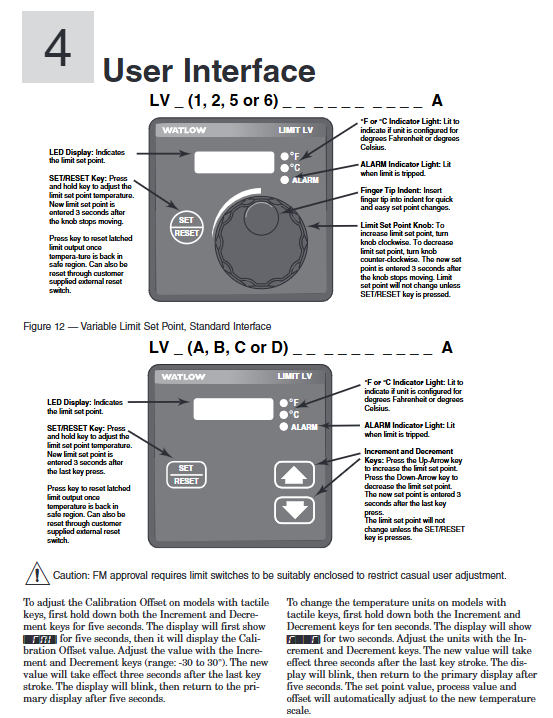
Rotary encoder version (Figure 12):
Display screen: 4-digit LED displays the set point, the ° F/° C indicator light displays the current unit, and the ALARM indicator light is on to trigger protection.
Operation: Press the SET/RESET button and rotate the encoder to adjust the set point. After the encoder stops for 3 seconds, it will automatically save; After triggering the protection, press the RESET button to reset (if the temperature meets the standard).
Button version (Figure 13):
Buttons: UP (increase), DOWN (decrease), SET/RESET (confirm/reset). Press the SET button for 3 seconds to enter adjustment mode, UP/DOWN button to modify the set point, no operation saved for 3 seconds.
Advanced function: Press and hold the UP+DOWN button for 5 seconds to enter calibration offset (-30~30 ° C); Press and hold for 10 seconds to switch between ° F/° C units, and the set point and measured value will be automatically converted after switching.
(3) Fault diagnosis and status indication
Solution to the meaning of series fault codes/indicator lights
LV [Er; In] sensor input fault (open/short circuit). Check the sensor wiring and replace the sensor
LS two LED alternate flashing dual sensors temperature difference>20 ° C or polarity reversed check sensor polarity, adjust installation position to ensure temperature difference ≤ 20 ° C
LS Limit LED flashes, Range LED lights up, temperature does not drop to reset threshold, wait for temperature to drop below "set point hysteresis", or power off to reset
The full range of ALARM LEDs are constantly on, triggering temperature limit protection to investigate the cause of overheating (such as heating tube adhesion), and ensuring temperature safety before resetting
2. Key configuration points
(1) Set point configuration
LF series: The set point is specified by the ordering model, such as "0120" in "LFC4JW0120AAAA" indicating a set point of 120 ° F. It is necessary to ensure that the set point is within the sensor range (such as 0-750 ° C for J-type thermocouples).
LV series: on-site adjustment, the steps are as follows:
Press the SET button for 3 seconds, and the display screen will flash to enter adjustment mode.
Rotary encoder (or press UP/DOWN key) to modify the set point, the range should be within the "low limit set point - high limit set point" (customized when ordering).
Stop the operation for 3 seconds, the display screen stops flashing, and the set point is saved.
LS series: The set point and hysteresis loop are specified by the ordering model, for example, in "LSF4HW0900220AA", "0900" represents the set point of 900 ° F and "220" represents the hysteresis loop of 20 ° F, which cannot be modified on site.
(2) Temperature unit configuration
LF/LS: Unit specified by ordering model (such as J-type thermocouple with "J" in ° C and "H" in ° F), cannot be switched on site.
LV: The button version supports unit switching, steps:
Press and hold the UP+DOWN key for 10 seconds, and the display screen will show "F" and "C".
Press the UP key to switch to ° F, and press the DOWN key to switch to ° C.
No operation for 3 seconds, the unit takes effect, and the set point and measured value are automatically converted (such as 100 ° C → 212 ° F).
(3) External reset configuration (LF/LV only)
Wiring: Connect an external momentary normally open switch (such as a button) to terminal 9 (RESET) and the common terminal (COM).
Function: After triggering the protection, press the external switch (or panel RESET button), and if the temperature has dropped to the reset threshold, output a reset; If the temperature does not meet the standard, resetting will be ineffective to avoid danger relief.
Installation and wiring specifications
1. Installation process (taking panel installation and rail installation as examples)
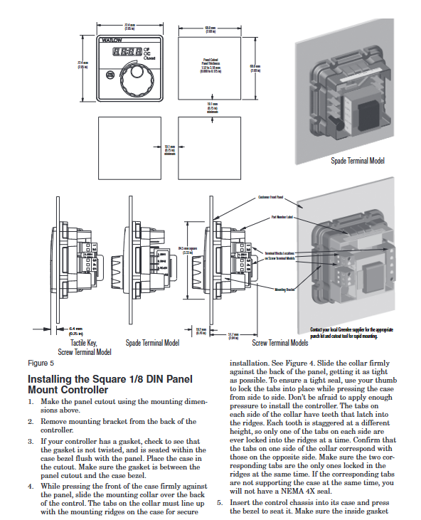
(1) 1/8 DIN panel installation (LV series, IP65 protection)
Preparation for Drilling: Drill holes on the panel in a size of 72.4mm × 72.4mm, with smooth edges and no burrs, and a panel thickness of 1.52-3.18mm.
Sealing gasket inspection: Confirm that the rubber sealing gasket on the front of the controller is not twisted and fits snugly into the groove of the housing to ensure IP65 protection.
Embedded controller: Insert the controller from the front of the panel, with the sealing gasket completely covering the edge of the opening without any offset.
Fixed bracket: Install the bracket from the back of the panel, ensuring that the bracket buckle is aligned with the ridge of the controller housing, press the bracket tightly against the panel, and lock the buckle with your thumb (both side buckles need to be locked at the same time to avoid uneven force causing sealing failure).
Check installation: Gently shake the controller without looseness; The front of the panel has no protrusions/indentations, and the sealing gasket has no compression deformation.
(2) DIN rail installation (LF series)
Rail preparation: Confirm that the DIN rail complies with DIN 50022 standard (35mm × 7.5mm), and is installed on a flat surface inside the cabinet, away from heat sources such as frequency converters and contactors.
Buckle installation: Insert the upper hook of the controller into the upper edge of the guide rail, press the lower part of the controller until the lower buckle "clicks" to lock onto the lower edge of the guide rail (if unable to lock, check if the guide rail is bent, adjust and retry).
Disassembly method: Press the release button on the upper part of the controller, while pulling the lower part forward to disengage the buckle from the guide rail, and remove the controller (disconnect the power and wiring before disassembly).
2. Wiring specifications and safety requirements
(1) Preparation before wiring
Power off confirmation: Before wiring, all relevant power sources must be disconnected, and a multimeter must be used to confirm that there is no voltage to avoid electric shock.
Wire selection:
Power wire: 12-18 AWG copper wire, current carrying capacity ≥ controller maximum current (LF/LV ≤ 0.5A, LS ≤ 0.1A).
Sensor wires: Thermocouples use the same type of compensating wire (such as JX-HS-FF for J-type), RTDs use 3-core shielded wire (20-24 AWG), and the shielding layer is only grounded at the sensor end.
Output wire: Depending on the load current, an additional RC suppressor (Watlow P/N 08040147-0000) needs to be connected in series for inductive loads.
(2) Core wiring example (LF/LV single circuit protection)
Power wiring: L1 (live wire) is connected to terminal 1, L2 (neutral wire) is connected to terminal 2, and a 2A slow melting fuse (250V) is connected in series. The live wire end needs to be connected to a circuit breaker (for easy power-off maintenance).
Sensor wiring (J-type thermocouple): The positive (non red) terminal of the thermocouple is connected to terminal 5, and the negative (red) terminal is connected to terminal 10. The extension wire needs to be a J-type compensating wire to avoid copper wires.
Output wiring: Relay COM terminal is connected to terminal 6, NO terminal is connected to one end of the contactor coil, and the other end of the coil is connected to L2; NC terminal is backup (can be connected to an alarm light), inductive load (contactor coil) is connected in parallel with an RC suppressor (between terminal 6 and NO terminal).
External reset wiring: One end of the external button is connected to terminal 9, and the other end is connected to terminal 6 (COM end). The button is of the instantaneous and constant on type (such as Schneider XB2-BA31).
(3) LS series dual sensor wiring
Power wiring: Connect L1 to terminal 1, L2 to terminal 2, and connect 2A slow melting fuses in series.
Dual sensor wiring (K-type thermocouple): Sensor 1 is connected to positive terminal 5 and negative terminal 10; The positive terminal of sensor 2 is connected to terminal 4, and the negative terminal is connected to terminal 9. The installation positions of the two sensors should be close (temperature difference ≤ 20 ° C).
Output wiring: The relay COM terminal is connected to terminal 6, and the NO terminal is connected to the heating tube power circuit. After triggering the protection, the NO terminal is disconnected, cutting off the heating tube power supply.
(4) Safety wiring requirements
Electrical isolation: Sensor cables, power cables, and output cables need to be wired separately (with a spacing of ≥ 10cm) to avoid electromagnetic interference; The grounding terminal of the controller (if any) needs to be connected to a protective ground (grounding resistance ≤ 4 Ω).
Installation in hazardous areas: Explosion proof junction boxes and armored cables are required for Class 1 Div. 2 hazardous areas, with terminal tightening torque ≥ 0.56 Nm, and live plug and unplug wiring is prohibited.
Anti misoperation wiring: strictly follow the terminal label for wiring, and do not reverse the positive and negative terminals of the power supply or the sensor (otherwise abnormal display or failure to trigger protection).
3. Analysis of Typical System Wiring Diagram (Industrial Oven Protection)
System composition: The main controller (Watlow Series CV) controls the temperature of the oven, while the LF series serves as redundant protection to prevent overheating caused by main controller failure.
Wiring logic:
The LF sensor and the main controller sensor are installed at different positions in the oven to avoid single point failures.
The LF output is connected in series with the main contactor coil circuit, and the main controller output is also connected in series with this circuit, forming a "double safety".
After triggering the LF protection, the contactor coil loses power, cutting off the power supply to the heating tube, and the ALARM light is on, requiring manual reset (or external button reset).
Troubleshooting and Maintenance
1. Common faults and solutions
Possible causes of malfunction, troubleshooting steps, and solutions
No display/action, ALARM light not on. 1. Power not connected or circuit breaker tripped
2. The fuse is blown
3. The safety interlock switch is not closed (such as the oven door switch). 1. Use a multimeter to measure the voltage at terminal 1/2 and confirm that the power supply is normal
2. Check the fuse of the power circuit. If it is blown, check if there is a short circuit in the load
3. Check the status of the interlock switch to ensure it is closed. 1. Connect the power supply and reset the circuit breaker
2. Replace the 2A slow melting fuse and repair the load short circuit
3. Close the interlock switch (such as closing the oven door)
Abnormal temperature reading (high/low), ALARM light triggered incorrectly. 1. Sensor type configuration error (e.g. actual J type, K type selected when ordering)
2. Reverse the wiring of the sensor
3. Excessive wire resistance (RTD)
4. The ambient temperature exceeds 70 ° C. 1. Check the ordered model and actual sensor type to ensure consistency
2. Swap the positive and negative poles of the sensor and observe if the reading returns to normal
3. Measure the resistance of the RTD wire. If it is greater than 1 Ω, replace the thick wire or shorten the length
4. Measure the temperature inside the cabinet. If it exceeds the temperature limit, add a ventilation fan. 1. If the configuration is incorrect, it needs to be recalibrated at the factory
2. Correct the polarity of the sensor wiring
3. Replace RTD wires with 20 AWG or more
4. Improve cabinet ventilation and reduce ambient temperature
Unable to reset after triggering protection. 1. The temperature has not dropped below the "set point hysteresis"
2. LS series power on reset
3. External reset switch fault: 1. Measure the actual temperature and confirm if it meets the standard (if the set point is 100 ° C and the hysteresis is 3 ° C, it needs to be lowered to below 97 ° C)
2. LS series needs to be disconnected from the power supply for ≥ 3 seconds and then powered on again
3. Measure the reset switch with a multimeter to see if it conducts when pressed. 1. Wait for the temperature to drop to a safe range
2. Perform power-off reset (LS series)
3. Replace the faulty reset switch
Two LEDs flashing alternately (LS series) 1. Dual sensor temperature difference>20 ° C
2. Sensor polarity reversed
3. One of the sensors is faulty. 1. Measure the actual temperature of the two sensors and confirm if the temperature difference exceeds 20 ° C
2. Swap the positive and negative poles of one of the sensors and observe if the flashing stops
3. Short circuit the two sensor terminals separately and observe if they still flash. 1. Adjust the sensor installation position to reduce the temperature difference
2. Correct the polarity of the sensor
3. Replace the faulty sensor
2. Daily maintenance and calibration
(1) Regular maintenance (monthly)
Appearance inspection: The panel is not damaged, the LED indicator light is normal (power light on, ALARM light off), the wiring terminals are not loose or oxidized, and the sealing gasket is not aged.
Functional testing:
Simulate overheating: Heat the sensor with a standard temperature source and confirm that the ALARM light will turn on and output an action when the temperature reaches the set point.
Reset test: After the temperature drops to a safe range, press the RESET button (or power off) to confirm the output reset and ALARM light off.
Cleaning: Wipe the panel with a dry cloth to remove terminal dust. Do not use corrosive cleaning agents such as alcohol and acetone.
(2) Annual calibration
Calibration tools: standard temperature source (such as FLUKE 9170), high-precision multimeter (such as FLUKE 8846A), standard resistance box (for RTD calibration).
Thermocouple calibration steps:
Set the standard temperature source to the midpoint of the sensor range (such as J-type thermocouple 300 ° C), and record the controller display value after stabilization.
If the error is greater than ± 1%, the LV series can adjust the calibration offset through the panel (long press the UP+DOWN button for 5 seconds to enter calibration mode and adjust to the standard value); The LF/LS series needs to be returned to the factory for calibration.
RTD calibration steps:
Use a standard resistance box to output 119.4 Ω (corresponding to 100 ° C, DIN curve), and record the displayed value of the controller.
When the error exceeds the limit, adjust the RTD wire compensation (3-wire system) or return to the factory for calibration.
(3) Fault record
Suggest establishing maintenance logs to record the time, symptoms, troubleshooting process, and solutions of faults, with a focus on recording:
Determine the frequency of sensor failures (such as open circuits and short circuits) and determine whether to replace the sensor or improve the installation environment.
The triggering reasons for over temperature protection, such as frequent adhesion of heating tubes, require early replacement of aging components.
Typical application scenarios
1. Industrial oven temperature protection (LF series)
Requirement: The oven main controller (such as PLC+temperature module) controls heating and requires redundant protection to prevent the main controller output from sticking and causing overheating (such as setting a point of 180 ° C and triggering protection for overheating at 200 ° C).
Configuration: LF series fixed set point of 200 ° C, K-type thermocouple (range 0-300 ° C), potting module installation, output connected in series to the heating tube contactor coil circuit, triggering to cut off the coil power supply.
Advantages: No user interface, preventing unauthorized modifications; The sealing structure is suitable for high temperature environments near the oven and has IP65 protection against dust.
2. Food baking oven protection (LV series)
Requirement: The baking oven needs to adjust the temperature frequently (such as baking bread at 180 ° C and cake at 160 ° C), and the maximum temperature should be limited to 220 ° C to prevent the batter from burning.
Configuration: LV series adjustable set point (range 100-220 ° C), J-type thermocouple, 1/8 DIN panel installation (IP65 protection), rotary encoder to adjust set point, output triggers alarm light and contactor trip.
Advantages: Quick on-site adjustment of set points, with anti misoperation design; IP65 protection is suitable for cleaning and spraying in food processing environments.
3. Heating protection for coating production line (LS series)
Requirement: If the heating tube in the coating and drying section loses control, it may cause a fire and requires high safety level protection. The set point is 120 ° C, dual sensor redundancy, and only power-off reset.
Configuration: LS series double K-type thermocouple, set point 120 ° C, hysteresis loop 5 ° C, DIN rail installation, output directly cuts off the power supply of the heating tube, triggering protection when the temperature difference between the two sensors is greater than 20 ° C.
Advantages: Dual sensor redundancy+power-off reset, in compliance with safety standards; Form A output is only used to cut off high-risk loads and has high reliability.
- OMRON
- ABB
- General Electric
- EMERSON
- Honeywell
- HIMA
- ALSTOM
- Rolls-Royce
- MOTOROLA
- Rockwell
- Siemens
- Woodward
- YOKOGAWA
- FOXBORO
- KOLLMORGEN
- MOOG
- KB
- YAMAHA
- BENDER
- TEKTRONIX
- Westinghouse
- AMAT
- AB
- XYCOM
- Yaskawa
- B&R
- Schneider
- KONGSBERG
- NI
- WATLOW
- ProSoft
- SEW
- ADVANCED
- Reliance
- TRICONEX
- METSO
- MAN
- Advantest
- STUDER
- DANAHER MOTION
- Bently
- Galil
- EATON
- MOLEX
- DEIF
- B&W
- ZYGO
- Aerotech
- DANFOSS
- Beijer
- Moxa
- Rexroth
- Johnson
- WAGO
- TOSHIBA
- BMCM
- SMC
- HITACHI
- HIRSCHMANN
- Application field
- XP POWER
- CTI
- TRICON
- STOBER
- Thinklogical
- Horner Automation
- Meggitt
- Fanuc
- Baldor
- SHINKAWA
- Other Brands
- UniOP
- KUKA
- Iba
- Beckhoff
-
 Basler D90 96801 100 PCB Card
 -
 Basler XR2002F Voltage Regulator (110 VAC, 48-480 Hz)
 -
 Basler SR8A-2B14B3A Regulator
 -
 Basler 9561500100 Module
 -
 Basler DECS-400 BE1-11 System
 -
 Basler DECS-100-B15 Excitation Control
 -
 Basler SCP 210 Frequency Controller
 -
 Basler SR4A-2B15B3A Static Voltage Regulator
 -
 Basler BE1-32R Power Relay
 -
 Basler PIA2400-17GM Power Interface Adapter
 -
 Basler MVC 232 Manual Voltage Control Module
 -
 Basler SSR 32-12 Static Voltage Regulator
 -
 Basler 5MW AVR Generator Voltage Regulator
 -
 Basler VR63-4B Voltage Regulator
 -
 Basler DECS-100-A05 AVR for Engine Generator
 -
 Basler DECS-100-B15 Automatic Voltage Regulator
 -
 Basler BE1-32R Directional Power Relay
 -
 Basler BE1-87B Differential Relay
 -
 Basler UFOV 260A Protective Module
 -
 Basler 9-2614-02-100 PCB Rev M
 -
Basler DECS-100-B15 Digital AVR
-
 Basler 9284900103 PS DECS-400N
 -
 Basler D4N3H1U Intertie Protection
 -
 Basler DECS-100-B15 A15 AVR
 -
 Basler KR4F Voltage Regulator
 -
 Basler BE26434 T14 Transformer
 -
 Basler SR8A-2B15B3A Regulator
 -
 Westinghouse 774B472A12 AR Relay
 -
Basler DECS-100-B15 AVR
-
Basler XR2002F Regulator 110V
-
Basler SR125-E Static Regulator
-
 Basler SSR 125-12 Regulator
 -
 Basler MOC2599 Motor Pot
 -
 Basler BE1-DFPR Feeder Relay
 -
 Basler CBS 305 Current Boost
 -
 Basler BE1-25 AutoSync
 -
 Basler MVC 300 Voltage Control
 -
 Basler BE3-25A AutoSync
 -
 Basler KR7FF Static Regulator
 -
 Basler 90-49000-100 Regulator
 -
 Basler 880 kVA Dry Type Transformer Specs
 -
 Basler Electric BE1-25 Sync-Check Relay Specs
 -
 Basler SSR 125-12 Voltage Regulator Specs
 -
 Basler Electric BE1-851 Overcurrent Relay Review
 -
Basler Electric 149D930G02 Control Sub-Assembly
-
 Basler Electric BE1-81O/UT Frequency Relay Specs
 -
 Basler Electric BE1-51/27C Overcurrent Relay
 -
 Basler Electric 149D956G02 Industrial Component
 -
Basler Electric BE1-51A Overcurrent Relay Specs
-
 Basler Electric BE1-40Q Loss of Excitation Relay
 -
 Basler DECS-200 Excitation Control System
 -
 Basler DECS-200 Voltage Regulator 56-277V AC / 125V DC
 -
Basler BE1-87T Transformer Differential Relay
-
 Basler RDP-110-S1 Protection Relay
 -
 Basler BE1-700V Digital Protective Relay
 -
 Basler BE1-951 Overcurrent Protection System
 -
 Basler DECS-300 Digital Excitation Control
 -
 Basler DECS-200 Digital Excitation Control
 -
 Basler DECS-200-1C Excitation Control System
 -
Basler DECS-200-1L Digital Excitation Control
-
 Basler Electric BE1-GPS Generator Protection System
 -
Basler Electric DECS-200-1C Digital Excitation Controller
-
 Basler Electric DECS125-15 Excitation Control with Power Module
 -
 Basler Electric BE1-87G Differential Relay
 -
 Basler Electric BE1-11 Protection System I5A3M2P2N0EA00
 -
Basler Electric DECS-200-1C Excitation Control System
-
Basler Electric BE1-11g Generator Protection Relay
-
Basler Electric DECS 125-15-B2C1 V2.0.9 Excitation Control
-
 Basler Electric BE1-81O/UT3ED1JA7N2F Frequency Relay
 -
Basler Electric BE1-81O/UT3EE1YB7N1F Frequency Relay
-
 Basler Electric DECS-200-1L Digital Excitation Control System
 -
Basler DECS125-15-B2C1 Excitation Control
-
 Basler 9507900205 SSR Retrofit Voltage Regulator
 -
 Basler BE2000E Digital Voltage Regulator
 -
 Basler BE1-GPS Generator Protection System
 -
Basler DECS-250-CN1CN1N Digital Excitation Control
-
 Basler DGC-2020 Genset Controller
 -
 Basler BE1-81O UT3ED1LA7N0F Frequency Relay (Variant)
 -
 Basler BE1-81O UT3EE1YA9S0F Frequency Relay (Variant)
 -
Basler BE1-81O Over/Under Frequency Relay
-
Basler DECS125-15 Digital Excitation Control
-
Basler Electric BE1-951 Overcurrent Protection System
-
 Basler Electric BE1-700V Digital Protective Relay
 -
 Basler Electric APR63-5 Automatic Voltage Regulator
 -
Basler Electric BE1-851 Overcurrent Protection System
-
Basler Electric DECS-250-LN1SN1N Excitation Control
-
 Basler Electric BE1-87T Transformer Differential Relay
 -
Basler Electric DECS-200-1L Excitation Control System
-
 Basler Electric 9310300100 DECS-300 Excitation Control
 -
 Basler Electric SSE-N 125-4.5KW Shunt Exciter Regulator
 -
 Basler Electric DGC-2020HD-5NS1DNSBA Genset Controller
 -
Basler Electric BE1-81-O/UT3EE1JB7N1F Frequency Relay
-
Basler Electric BE1-81T1EE1WA0N1F Frequency Relay
-
 Basler Electric BE1-25M1EA6PN5R1F Sync-Check Relay
 -
 Basler Electric BE1-GPS Generator Protection System
 -
Basler Electric DECS-250-LN1SN1N Excitation Control Rev V
-
 Basler Electric DECS-250-CN2CN1N Excitation Control
 -
Basler Electric BE1-50/51B-207 Overcurrent Relay
-
Basler Electric DECS-300-C0N0 Excitation Control System
-
Basler Electric DECS-200 Digital Excitation Control System
-
Basler Electric DECS-250-LN1CN1N Excitation Unit
-
Basler Electric DECS-250 LN2SA1D Excitation Unit Specs
-
Basler Electric BE1-87T Transformer Relay Review
-
Basler Electric BE1-11 Protection System
-
Basler Electric BE1-GPS100-E4N1H1N Protection System
-
 Allen-Bradley 442G-MABH-R Safety Module
 -
 Beckhoff CX1030-0111 PLC Assembly Profile
 -
 FANUC IC693CPU364 PLC Module
 -
 Orange Denmark Type 200816 220 PLC Specs
 -
 OMRON C200H-SNT31 Sysmac PLC Module
 -
 Allen Bradley 20AB022A3AYNANC0 PowerFlex 70
 -
 OMRON C200HW-PCU01 Position Control Unit
 -
 ABB AO845A-eA Analog Output Module
 -
 OMRON CJ1M-CPU22 CPU Unit
 -
 Allen Bradley 100-E265ED11 Contactor
 -
 Honeywell 51304511-100 Interface Module
 -
 SOLEXY BXF3S0101N0018 Gateway Module
 -
 OMRON CJ2H-CPU65 CPU Unit
 -
 Automation Direct GS2-45P0 AC Drive
 -
 M68-2000 2-Axis Motion CNC Controller
 -
 OMRON CJ1M-CPU11 V3.0 PLC CPU Unit
 -
 OMRON CJ1W-NC413 4-Axis Positioning Controller
 -
 OMRON 3G2A3-PRO16 Programming Console HMI
 -
 Siemens 3VT8440-2AA04-2GA2 Molded Case Circuit Breaker
 -
 Siemens 3RT5045 Contactor Series
 -
 OMRON C200HS-CPU01-E SYSMAC PLC Controller
 -
 OMRON C500-NC103-E Positioning Control Unit
 -
 OMRON CJ1W-TC001 Temperature Control Unit


