
GE VME-3125A Isolation Scan 12 Bit 32 Channel Analog to Digital Converter Board (6U)
Product Name: VME-3125A Isolation Scan 12 Bit 32 Channel Analog to Digital Converter Board (with Built in Testing Function)
Production company: Abaco Systems
Main features
32 single ended or 16 differential inputs
Automatic scanning, continuously digitizing input and storing results in dual port data registers
Input range: Bipolar ± 50mV to ± 10V, Monopolar 0-100mV to 0-10V, or 0 to 25mA current input options
Jumper programmable gains x1, x10, x100
1 12 bit A/D converter with built-in tracking and holding functions
Start scanning without software startup
Pause and lock scanning function, which can achieve 40KSPS arbitrary channel sampling based on channel pointer
Optional A/D range: ± 5V, ± 10V, 0 to+10V
40kHz total conversion rate
Support real-time built-in testing (BIT)
Input connector compatible with discrete and ribbon cables
Optional data encoding: offset binary or binary complement
Over voltage protect
Low pass input filter: 50kHz, optional 40Hz
Pull down resistor to prevent input floating
1000V analog ground/digital ground isolator
GE VME-3125A Isolation Scan 12 Bit 32 Channel Analog to Digital Converter Board (6U)
Basic Information
Product Name: VME-3125A Isolation Scan 12 Bit 32 Channel Analog to Digital Converter Board (with Built in Testing Function)
Production company: Abaco Systems
Main features
32 single ended or 16 differential inputs
Automatic scanning, continuously digitizing input and storing results in dual port data registers
Input range: Bipolar ± 50mV to ± 10V, Monopolar 0-100mV to 0-10V, or 0 to 25mA current input options
Jumper programmable gains x1, x10, x100
1 12 bit A/D converter with built-in tracking and holding functions
Start scanning without software startup
Pause and lock scanning function, which can achieve 40KSPS arbitrary channel sampling based on channel pointer
Optional A/D range: ± 5V, ± 10V, 0 to+10V
40kHz total conversion rate
Support real-time built-in testing (BIT)
Input connector compatible with discrete and ribbon cables
Optional data encoding: offset binary or binary complement
Over voltage protect
Low pass input filter: 50kHz, optional 40Hz
Pull down resistor to prevent input floating
1000V analog ground/digital ground isolator
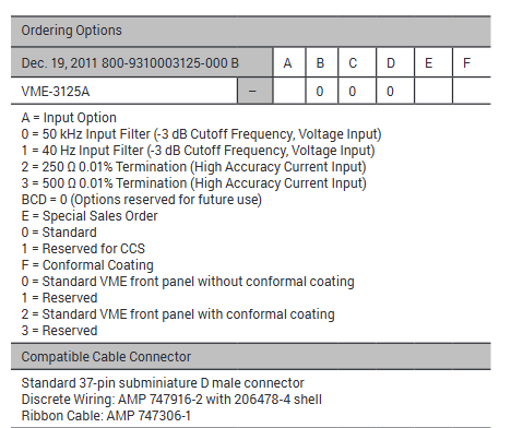
Ordering Options
Option Description
A (input option) 0=50kHz input filter (-3dB cut-off frequency, voltage input); 1=40Hz input filter (-3dB cut-off frequency, voltage input); 2=250 Ω 0.01% terminal (high-precision current input); 3=500 Ω 0.01% terminal (high-precision current input)
BCD 0 (reserved for future options)
E (Special Sales Order) 0=Standard; 1=Reserved for CCS
F (conforming coating) 0=standard VME front panel without conforming coating; 1=Reserved; 2=Standard VME front panel with conforming coating; 3=Reserved
Compatible cable connectors
Standard 37 pin ultra small D-type male connector
Discrete cabling: AMP 747916-2 (with 206478-4 enclosure)
Ribbon cable: AMP 747306-1
Functional characteristics
1. Basic Introduction
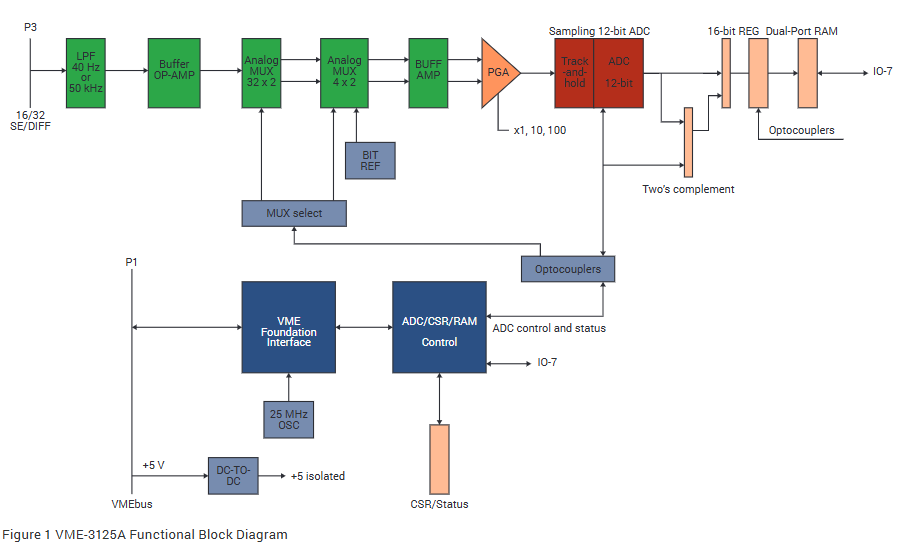
VME-3125A provides isolated 12 bit analog-to-digital conversion with 32 single ended analog voltage input channels (16 differential) for VMEbus's 6U Eurocard. The optional gain and A/D range support an input voltage range of ± 50mV to ± 10V, and the current input option supports 32 single ended channels with ranges of 0 to 20mA, 4 to 20mA, and 5 to 25mA. To minimize system software overhead, all inputs are continuously scanned and digitized at a total sampling rate of 40000 samples per second, and the measurement data of each channel is accessed by VMEbus at any time through a dual port data register. For voltage input, a 40Hz low-pass input filter can be selected to minimize the impact of system noise, and the standard unit is equipped with a 50kHz low-pass filter.
2. Core functions
Programmable Gain Amplifier (PGA): Jumper options include series voltage gain x1, x10, or x100 for all channels; For voltage input, the full range of the A/D converter can be selected as ± 5V, ± 10V, or 0 to+10V; the data encoding software can be selected as offset binary or binary complement code
Input configuration: The input can be configured with 16 differential voltage channels or 32 single ended voltage or current channels through jumper wires; A single front panel 37 pin ultra small D-type connector provides connections for all input channels
Working mode: All 16 or 32 input channels are continuously scanned at the maximum sampling rate, and the resulting data is stored in a dual port data register for VMEbus to access; After any reset operation, the scan automatically starts without the need for additional programming to initiate the A/D conversion process
Built in Test Function (BIT): By selecting the BIT working mode, the operation of PGA, ADC, and related control logic can be verified. In this mode, the internal reference voltage is applied to the input of PGA, bypassing the analog input multiplexer. All data channels read through the control interface will reflect the selected BIT reference voltage
3. Features related to VMEbus
Compliance: Compliant with VMEbus standard ANSI/IEEE STD 1014-1987, IEC 821 and 297, with 6U external dimensions
Board address: The physical address is selected through the onboard address jumper, using VMEbus address lines A07 to A15; The VME-3125A board occupies 128 bytes of address space and can be located on any 64 word boundary of the short I/O (A16) space
Address Modifier: Address modifier bits are selected and decoded through jumpers to respond to non privileged short I/O access, monitoring short I/O access, or both access privileges
4. System reset and indicator lights
System reset: System reset establishes the following board states: all channels automatically scan, front panel diagnostic LED indicator lights up, offset binary data format
Front panel system diagnostic LED: The software controlled front panel LED lights up when the system is reset and can be turned off under software control to provide an external indication that the built-in test has been completed
Simulate input data format
The analog input is digitized and stored in 32 dual port data registers (16 registers for differential operation) as a 12 bit right aligned digital value. The software can select data codes as offset binary and binary complement. In binary complement encoding, the sign bit (D11) is extended to the most significant bit (D12 to D15) of the data register.
Input characteristics
(At+25 ° C and rated power supply, unless otherwise specified)
Number of channels: 32 single ended or 16 differential voltage input channels; 32 single ended current input channels
Voltage range: ± 50mV to ± 10V (bipolar) or 0 to+100mV, 0 to+10V (unipolar), factory configured for ± 10V input range
Current terminal: Suitable for single ended, 0-10V, and X1 gain unipolar configurations, with two options: 250 Ω 0.01% and 500 Ω 0.01%
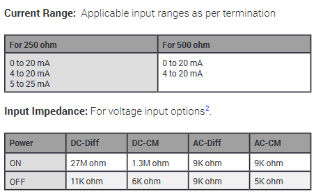
Current range: According to the applicable input range of the terminal, 250 Ω corresponds to 0 to 20mA, 4 to 20mA, 5 to 25mA; 500 Ω corresponds to 0 to 20mA, 4 to 20mA
Input impedance: When the power is turned on, the voltage input options are DC differential 27M Ω, DC common mode 1.3M Ω, AC differential 9K Ω, and AC common mode 9K Ω. When the power is turned off, the DC differential 11K Ω, DC common mode 6K Ω, AC differential 9K Ω, and AC common mode 5K Ω
Input bias current: minimum 44nA/maximum 90nA
Input bias current drift: 0.30nA/° C
Common mode voltage (CMV): When the differential input is at zero input signal, the maximum ± 11V; CMV refers to the common analog ground of all inputs; For other gains, the formula is ± 11V=(VCM+Vddiff/2) * gain
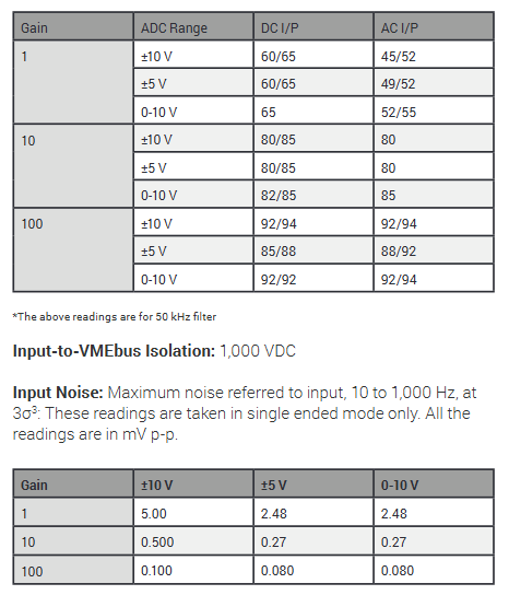
Common mode rejection ratio (CMRR): Differential input has different minimum/typical values (dB) at different gains and ADC ranges when the source is unbalanced at 350 Ω and the frequency is between DC and 60Hz
Input to VMEbus isolation: 1000VDC
Input noise: Under 10 to 1000Hz and 3 σ, different gains and ranges have different maximum noise (mV p-p) in single ended mode
Each input bandwidth: DC to Fc, where Fc is 50kHz for a 50kHz filter and 40Hz for a 40Hz filter option unit
Input filter: Single pole passive low-pass filter, -3dB at 50kHz or 40Hz ± 20% (voltage input option only)
Overvoltage protection: maximum ± 40V continuous during power supply; ± 25V during power outage
Transmission characteristics
(At+25 ° C and rated power supply, unless otherwise specified)
Measurement resolution: 12 bits
Channel scanning rate: minimum 40KSPS (thousand samples/second) total rate
Voltage transfer function:
E IN=E LO+E FSR × 4096N ADC, where E IN=input voltage, E LO=lower end of input range,
E FSR=full-scale input range, N ADC=A/D converter reading
Current transfer function: I IN=R TERMINATION E FSR × N ADC/4096, where I IN=input current (ampere), E FSR=10V (unipolar), N ADC=A/D converter reading, R TERMINATION=250 Ω or 500 Ω options
Input range of A/D converter: ± 5V, ± 10V, 0 to+10V, jumper optional
Input gain of A/D converter: x1, x10, x100 (± 0.3%, jumper optional)
Accuracy: Voltage input=± 0.04% reading ± 0.03% range ± 2.0mV; Current input (-200, -300 options)=± 0.05% range ± 2.44 μ A
Temperature stability: The voltage input board option (mV/° C) is ± 30PPM reading ± 25PPM range ± 20 μ V; The current input board option (μ A/° C) is ± 40PPM reading ± 25PPM range ± 20nA
Long term drift: ± 50PPM reading ± 45PPM range ± 100 μ V every 1000 hours
Channel crosstalk: In ± 10V bipolar and gain X1 differential mode, different options have different typical/maximum values (dB) for DC and AC inputs
BIT reference voltage: Software options include 0.000V,+4.980V,+0.4928V, and 9.91mV
BIT reference accuracy: ± 30mV ± 30PPM/° C (4.98VDC)
Physical/Environmental Specifications
Size: Standard VME double height board 160 × 233.5mm
Power requirement:+5VDC (± 5%), maximum 1.5A
Temperature: Operating temperature from 0 ° C to+65 ° C; Storage temperature from -40 ° C to+85 ° C
Humidity: Operating relative humidity of 20% to 80%, no condensation
Cooling: forced air convection (standard VME slot)
MTBF: Contact the factory
Input connector (P3): 37 pin ultra small D-type female connector
- OMRON
- ABB
- General Electric
- EMERSON
- Honeywell
- HIMA
- ALSTOM
- Rolls-Royce
- MOTOROLA
- Rockwell
- Siemens
- Woodward
- YOKOGAWA
- FOXBORO
- KOLLMORGEN
- MOOG
- KB
- YAMAHA
- BENDER
- TEKTRONIX
- Westinghouse
- AMAT
- AB
- XYCOM
- Yaskawa
- B&R
- Schneider
- KONGSBERG
- NI
- WATLOW
- ProSoft
- SEW
- ADVANCED
- Reliance
- TRICONEX
- METSO
- MAN
- Advantest
- STUDER
- DANAHER MOTION
- Bently
- Galil
- EATON
- MOLEX
- DEIF
- B&W
- ZYGO
- Aerotech
- DANFOSS
- Beijer
- Moxa
- Rexroth
- Johnson
- WAGO
- TOSHIBA
- BMCM
- SMC
- HITACHI
- HIRSCHMANN
- Application field
- XP POWER
- CTI
- TRICON
- STOBER
- Thinklogical
- Horner Automation
- Meggitt
- Fanuc
- Baldor
- SHINKAWA
- Other Brands
- UniOP
- KUKA
- Iba
- Beckhoff
- ADLINK
-
 LTi SO22.003.0080.0000.0 Servo Controller
 -
 LUST CDB32.004.C2.4.SH Servo Drive
 -
 LTi LSP06-015-320-60-B0H1MY170 Unit
 -
 LTi Motion PM-D35.1WVA02 Module
 -
 LTi BR-090.03.540.UR.H38 Brake Resistor
 -
 LTi FGP 111/002-25 AA Servo Motor
 -
 LTi ServoOne Junior SO22.006 Servo Controller
 -
 LUST CDA34.008.W1.4.BR Drive Controller
 -
 LUST CDA34.017.W3.0 Drive System
 -
 LUST CDE32.004.C2.4 Drive Controller
 -
 LTI CDE32.004.C3.0 Servo Drive
 -
 LUST LSH-097-2-30-560 Servo Motor
 -
 LUST CDB32.003.C2.4 Servo Controller
 -
 LUST CDB32.003.C2.3 Servo Controller
 -
LUST CDA34.017.W3.0 Drive Controller
-
 LTI Tools LT-1400Q Torque Extension
 -
 LUST SO82.004.0030.0060.2 Servo Drive
 -
 LUST CDA32.006.C3.0.H09 Drive Controller
 -
 LTI CDB32.004.C3.7.SH Servo Drive
 -
LTI LSH-127-3-30-560 Servo Motor
-
LUST CDA34.017.C2 Servo Drive
-
 LTI CM-DPV1 3.0 V2.25-00 Module
 -
 LTI CDE34.005 W2.4 Servo Drive Controller
 -
 LUST LR32.8 0925.0018 Line Choke
 -
LUST LTi CM-DPV1 3.0 Communication Module
-
LUST LTI Drives CCD34.024.W2.1.BR Servo Drive
-
 Lust LTi Drives CDE32.008.W2.2.BR Positioning Controller
 -
LTi DRiVES LSH-050-3-45-320/T1 Servo Motor
-
LUST LTI Drives CDA34.006.W1.5.BR Inverter
-
 LUST LTI DRIVES VF1204S Frequency Inverter
 -
 Lust LTI Drives EMC100.1 Network Filter
 -
 LUST LTi DRIVES LSH-097-1-30-560/T1 Servo Motor
 -
LTi Drives Lust CDA34.017.W3.0 Servo Controller
-
 LUST LTI DRIVES CDE32.003 Frequency Inverter
 -
LUST CDB34.003.C2.0.H15 Servo Drive Positioning Controller
-
 LTi DRiVES SO84.076.S030.0001.2-W Servo Drive
 -
 LUST LTI Drives CDE32.003 Frequency Inverter
 -
 LUST LTI Drives CDA34.017.C2.CP Servo Controller
 -
LTI Motion CDE32.004.C2.4 Servo Drive
-
LUST LTI DRIVES CDE34.017.W2.0.H18 Inverter
-
 LUST LTI Drives BR-200.02.540.UR Braking Resistor
 -
 LTi DRiVES LR32.8 Line Reactor
 -
Lust LTI Drives CDS44.032 Inverter
-
LUST LTI DRIVES CDB34.008 W2.4 Frequency Converter
-
 LTI DRIVES SO84.012.1030.0000.2 Servo Drive
 -
 LTI SO84.024.1030.0011.2 Servo Drive Controller
 -
 LTi Drives SO84.076.S030.0001.2-W 52.5 kW Controller
 -
LTi LUST SO84.012.1030.0000.2 Servo Drive Controller
-
LTI Drives SO84.008.0020.1070.1 Servo Controller
-
 LTI Motion CDE32.004.C3.0 Positioning Controller 1.6 kVA
 -
LUST LTi Drives CDB34.010C2.4 Servo Drive Controller
-
Lust LTi Drives CDD32.003.C2.0 Servo Controller
-
 Lust LTi Drives CDB32.003C2.3 Servo Controller UM-8I40
 -
 LTi Drives SO CM-1.0003.110C.0 Control Module
 -
 LTI Drives GmbH LR34.44-UR Servo Drive Unit
 -
LTI DRIVES VF1202S Frequency Inverter
-
 LTi ServoOne Junior SO24.004 Servo Drive
 -
Lust CDA34.003 C1.4 LTI Servo Drive
-
 LUST LTi Drives CM-CAN1 Communication Module
 -
LUST LTi Motion CDB22.004 CDB2000 Drive
-
LUST Lti Drives CDE32.003 Frequency Drive
-
LTI VF1406M.C9.PT1.BR1 Frequency Drive
-
LUST LTI Drives CDA34.006 W3.0 Servo Drive
-
Lust LTI Drives CDA34.017.C2.CP Servo Controller
-
LTi DRiVES LST-097-5-30-560/T1 Servo Motor
-
LTi Drives LSH-050-2-45-320/T1 Servo Motor 4500rpm
-
 LUST LTI Drives VF1204S G10 FA VFD 0.75 kW 230VAC
 -
 LTi Drives LST-097-3-30-560/T1 1R Servo Motor
 -
 LTI Servo One Junior SO22.003.0082.0000.0 Controller
 -
LTI Drives GmbH SO22.003.0042.0000.0 Servo Controller
-
 LUST LTi CDB32.004.C2.4.SH Servo Drive 24-48V
 -
LTi Drives LST-097-5-30-560/T1 1R Servo Motor
-
 LUST LTI Drives CM-CAN1 3084464 Communication Module
 -
LUST LTi Drives CDE32.003.C2.3 Positioning Controller 230V
-
 LUST LTi Drives SO84.020.0020.0000.2 Servo One 20A
 -
LTI DRiVES CDB34.003 Servo Drive
-
LTI DRiVES CDE34.010 D2.4 Frequency Inverter
-
 LTi DRiVES BR-090.03.540-UR Braking Resistor
 -
 LTI SO84.012 Servo Drive
 -
 LTi Drives LSH-050 Servo Motor
 -
LTi Drives SO84.004 Servo Controller
-
LTI DRiVES LSN-127 Servo Motor
-
LUST CDA34.006 W3.0 Servo Controller
-
 LTi DRiVES SO84.004 Servo Drive
 -
LUST LTi DRiVES LST-097-3-30-560/T1.1R Servo Motor
-
LTi Drives CDE32.003.C2.4 Software LBXR41024B014
-
 LTI Motion Servo One SO84.006.0173.1100.1 Controller
 -
LTi Drives LSH-074-2-30-320/T1 G6.1M Servo Motor
-
LUST CDB22.004.0111.00.0 LTi Drives Servo Controller
-
 Lust So84.012.0030.1700.2 LTi Drives Servo Controller
 -
LTi Drives Lust VF1204S G10 FB I6 M3 Drive Module
-
LTI Drives GmbH SO84.008.0020.0000.2 Servo Controller
-
Lust CDA34.006.C2.0 LTI Drives Servo Controller 2.2 kW
-
LTi Drives Lust CDA34.017.W3.0 Control Unit 7.5 kW
-
LTi Drives CDE34.010 Positioning Controller 10A
-
Lust LTi Drives CDA34.010 W3.0 Frequency Inverter
-
LTi SO22.003.0010.0000.0 ServoOne Junior Drive
-
LUST LTi Drives CDA32.008 Servo Drive
-
LUST LTi DRIVES LSH-074 Servo Motor
-
Lti CDB32.004.C2.4.SH AC Servo Drive
-
Lust LTi Drives VF1202S Frequency Inverter
-
Lust LTI Drives CDB32.004.C3.0.SH Servo Controller
-
LUST SO84.012.0030.1700.2 Servo Drive
-
Lust LTi CDB32.004 Servo Drive
-
LUST LTI Drives CDA34.006 Servo Drive
-
LTi DRiVES BR-090.03.540-UR Braking Resistor
-
Lust LTI Drives CDA34.017 Servo Controller
-
Lust LTi Drives CDE34.010.D2.4 Positioning Controller 10A
-
LTi Drives LSH-050-3-30-48/T1 PM Servo Motor
-
 LTI CDD34.005.C2.1 Servo Drive Controller
 -
LUST LTI Drives CDB32.003.C2.4 Servo Drive
-
LTI D-35633 Drive Servo Drive Controller
-
 LTI Drives GmbH SO22.003.0042.0000.0 Servo Controller
 -
LTi Drives SO84.006.1030.0000.2 Servo Controller
-
LUST LTi Drives CDA32.008 C1.4 HF V180.15 1.5 kW
-
 LTI Drives Servo One SO84.045.0010.0001.2-W 22 kW
 -
Lust LTI CDE32.003.C2.4 Servo Drive Controller
-
LUST LTI Drives CDA34.003 Servo Controller
-
LUST LTI Drives CDA32.006 Servo Controller
-
Lust LTi Drives CDE32.004 Servo Drive
-
LUST LTi Drives SO84.012 Servo Controller
-
 LTI DRIVES LSH-060 Servo Motor
 -
LUST LTI Drives CDE32.004 with CM-DPV1
-
LTi DRiVES SO84.016 Servo Drive
-
LTI Drive CM-DPV1 Communication Module
-
LTi DRiVES DSM4-05.4-20R82-400 Servo Motor
-
LUST LTI Drives CDA34.003 Servo Controller
-
LTI Drives Servo One SO84.045.0010.0001.2-W 22 kW


