
Westinghouse WGen5500 Generator
Westinghouse WGen5500 Generator
Core specifications of the product
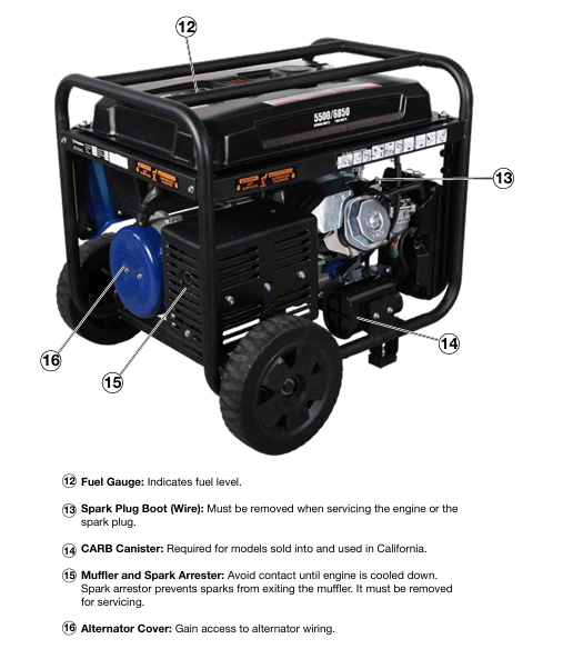
Power and electrical parameters: operating power of 5500 watts, peak power of 6850 watts; Rated voltage 120/240V, frequency 60Hz, total harmonic distortion<23%; The operating current is 23 amperes and the peak current is 28 amperes.
Core configuration: 420cc OHV four stroke engine (13 horsepower), rated speed of 3600RPM; The fuel tank capacity is 25 liters (6.6 gallons), with a range of 20 hours under 1/4 load and 15 hours under 1/2 load; Oil capacity 1.1 liters, recommended SAE 10W30 oil; Spark plug model Torch F7TC, clearance 0.027-0.032 inches (0.70-0.80mm).
Structure and Function: Equipped with one 120/240V 30A twist lock socket (NEMA L14-30R) and two 120V 20A GFCI dual socket sockets (NEMA 5-20R); Including VFT data center (displaying voltage, frequency, and cumulative operating time); Equipped with 10 inch polyurethane wheel and single handle foam grip, easy to move; Net weight 174 pounds (88kg), supports transfer switch connection.
Environment and certification: certified by EPA, CARB, CSA; For every 1000 feet increase in altitude, the power decreases by 3.5%. For altitudes above 5000 feet, a high-altitude carburetor kit (part number 140545) must be installed; Operating noise of 72dBA, equipped with spark arrester.
Safety operation standards (core focus)
1. High risk warning and contraindications
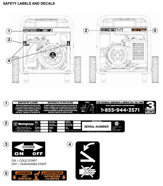
Risk of carbon monoxide poisoning: It is strictly prohibited to use in enclosed/semi enclosed spaces such as indoors, garages, and basements. It can only be operated in outdoor ventilated areas and kept at least 15 feet (4.5 meters) away from doors, windows, ventilation openings, and air conditioning air intakes; Suggest installing a carbon monoxide detector.
Fire and explosion risks: The machine must be stopped and cooled down before refueling; Do not overfill (the oil level should not exceed the neck of the fuel tank filling port); Keep away from sources of fire, sparks (cigarettes, static electricity); When there is a fuel leak, wipe it clean immediately and wait for the area to dry before starting; Do not store fuel indoors during storage.
Electric shock risk: Do not use in damp environments, rainy or snowy weather; Do not touch live terminals and exposed wires during equipment operation; Use grounded three core extension cables and prohibit the use of damaged or aged cables; The connection to the building power grid must be installed by a certified electrician to ensure isolation from the mains power supply.
Other taboos: Not suitable for powering medical equipment; Prohibition of modifying equipment; Overloading operation is prohibited; Do not move or tilt the device while it is running; Prohibit starting with load.
2. General safety requirements
Ensure that there are no obstacles around the equipment during operation and avoid touching high-temperature components such as mufflers and engines (after cooling); Wear protective equipment (gloves, goggles) to avoid direct skin contact with engine oil and gasoline; Wash hands promptly after operation.
Before starting, all loads must be disconnected to avoid damaging the equipment during loaded startup; Grounding must comply with local regulations. If connecting to building systems, an electrician must confirm whether a grounding rod (copper wire ≥ 10 AWG) is required.
Before transportation, the equipment needs to be cooled down and kept level. If necessary, the fuel should be drained; When storing, keep away from sources of fire and heat (such as water heaters, stoves, etc.), and do not use wires or tools to cross the two poles of the battery (if it is an electric starting model).
Assembly and start-up process
1. Open box inspection and assembly
(1) List of unboxing items
Core components: Generator host, wheel assembly (2 pieces), axle pin (2 pieces), washer (2 pieces), M8 × 16mm flange bolt (4 pieces), split pin (2 pieces).
Tools and consumables: spark plug socket wrench, funnel, 1.1L SAE 10W30 engine oil.
Documents: User Manual, Quick Launch Guide, Product Registration Card.
(2) Assembly steps (requiring collaboration between two people to avoid single person handling)
Foot installation: Place the generator on a flat surface and fix the feet on both sides of the frame with M8 flange bolts to ensure a secure installation.
Wheel installation: Insert the axle pin through the washer and wheel into the frame axle bracket, ensuring that the bolt hole faces inward towards the generator; Lock the axle pin hole with an open-ended pin, and repeat the operation on the other side (the wheel is only used for manual movement, dragging or road driving is prohibited).
2. Preparation before startup
Location selection: Outdoor ventilated area, at least 15 feet (4.5 meters) away from buildings and combustibles, on a horizontal and dry surface, avoiding loose materials (sand, grass debris) to prevent blockage of air vents.
Oil inspection:
Engine oil: The new machine has no engine oil and needs to be added to the "MAX" mark on the dipstick (place the cold machine horizontally, wipe the dipstick dry, fully screw it in, and then remove it for inspection).
Fuel: Add unleaded 87-93 gasoline with ethanol content ≤ 10%; Clean the fuel tank after refueling and check for leaks.
Load and grounding: Disconnect all electrical equipment connections; Grounding must comply with local regulations. If connecting to building systems, an electrician must confirm whether a grounding rod is required.
3. Startup and shutdown operations
(1) Start the process
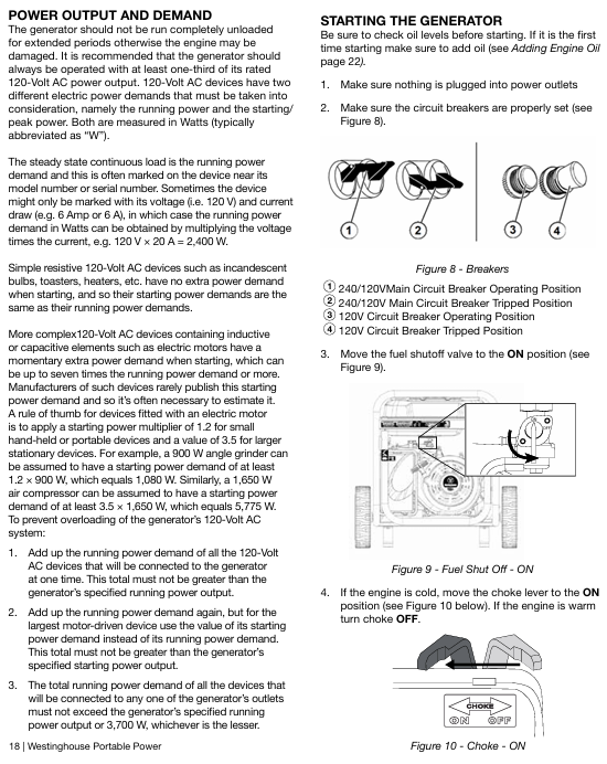
Turn the fuel valve to the "ON" position.
Cold machine: Turn the air damper to "ON"; Heat engine: Set the choke to "OFF".
Push the engine control switch to 'RUN'.
Slowly pull the recoil start rope until the resistance increases, and quickly pull upwards to start (the longest single pull should not exceed 5 seconds, failure should be attempted again with a 10 second interval).
After the engine starts, wait for the RPM to stabilize and gradually retract the choke to "OFF".
Connect electrical equipment (following the principle of "high power first, low power later" to avoid overloading).
(2) Shutdown process
Normal shutdown: Disconnect all loads → Run without load for 3-5 minutes → Turn the engine control switch to "STOP" → Close the fuel valve; Long term non use requires closing the fuel valve and allowing the engine to run until it shuts down on its own (depleting the fuel in the carburetor).
Emergency stop: Simply turn the engine control switch to "STOP" (only used in case of malfunction or danger).
Key maintenance operation details
(1) Oil change
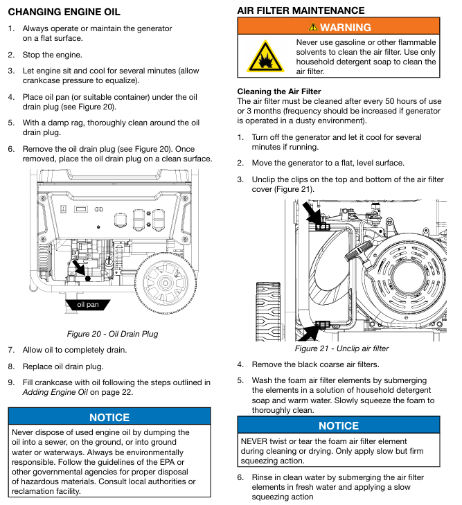
Place the refrigeration unit horizontally, clean the area around the oil discharge port, and place the oil pan.
Remove the oil drain plug, drain the old oil, close the drain plug and tighten it.
Add recommended engine oil to the "MAX" mark on the dipstick through the oil filler port, install the dipstick and filler cap, start the engine and check for leaks.
Waste engine oil should be disposed of according to environmental protection requirements and should not be dumped into sewers, ground or water sources at will.
(2) Evacuation of carburetor float (before long-term storage)
Stop the generator for cooling, keep away from sources of fire, and place a container under the carburetor.
Loosen the bottom screw of the carburetor float, drain the remaining fuel, and tighten the screw.
(3) Storage maintenance
Key points for storage duration operation
No special treatment is required within one month, keep the oil and fuel normal, and regularly check the fluid level
Clean the equipment after more than one month → Drain the fuel tank and carburetor float → Change the engine oil → Inject 1 tablespoon of engine oil into the spark plug hole, pull the starting rope to make the piston run (protect the cylinder wall) → Clean the spark arrester → Store in a dry and ventilated place, away from fire sources
Common troubleshooting
Possible causes and solutions for the fault phenomenon
The engine is running but there is no power output. 1. The circuit breaker has tripped; 2. The power cord is not securely plugged in; 3. Power cord/electrical equipment malfunction; 4. GFCI socket tripped; 5. Internal equipment malfunction: 1. Reset the circuit breaker and check for overload; 2. Re plug the plug (the 240V socket needs to be turned clockwise by 1/4 turn); 3. Replace the power cord or test the normal equipment; 4. Press the GFCI reset button; 5. Send to authorized service points
The engine cannot start/stalls after starting. 1. The fuel valve is closed; 2. Lack of fuel/deterioration of fuel; 3. Blockage of oil circuit; 4. The air filter is dirty; 5. Low oil level (low oil protection); 6. Spark plug malfunction/improper clearance; 7. Spark eliminator blockage 1. Open the fuel valve; 2. Add fresh fuel; 3. Clean the oil circuit; 4. Clean/replace the filter; 5. Add engine oil; 6. Adjust/replace spark plugs; 7. Clean the spark eliminator; If it is invalid, send it for repair
Sudden shutdown of generator: 1. Lack of oil; 2. Low oil level (low oil protection); 3. Excessive load 1. Oil replenishment; 2. Add engine oil; 3. Reduce load after restart; If it is invalid, send it for repair
Unstable engine operation/speed fluctuation 1. Air filter blockage; 2. Frequent load switching; 3. Equipment malfunction: 1. Clean the filter; 2. Load fluctuations are a normal phenomenon and do not require any handling; 3. Send to authorized service points
GFCI socket has no power. 1. The socket trips; 2. Socket malfunction: Press the reset button; 2. Send for repair and replacement of sockets
- OMRON
- ABB
- General Electric
- EMERSON
- Honeywell
- HIMA
- ALSTOM
- Rolls-Royce
- MOTOROLA
- Rockwell
- Siemens
- Woodward
- YOKOGAWA
- FOXBORO
- KOLLMORGEN
- MOOG
- KB
- YAMAHA
- BENDER
- TEKTRONIX
- Westinghouse
- AMAT
- AB
- XYCOM
- Yaskawa
- B&R
- Schneider
- KONGSBERG
- NI
- WATLOW
- ProSoft
- SEW
- ADVANCED
- Reliance
- TRICONEX
- METSO
- MAN
- Advantest
- STUDER
- DANAHER MOTION
- Bently
- Galil
- EATON
- MOLEX
- DEIF
- B&W
- ZYGO
- Aerotech
- DANFOSS
- Beijer
- Moxa
- Rexroth
- Johnson
- WAGO
- TOSHIBA
- BMCM
- SMC
- HITACHI
- HIRSCHMANN
- Application field
- XP POWER
- CTI
- TRICON
- STOBER
- Thinklogical
- Horner Automation
- Meggitt
- Fanuc
- Baldor
- SHINKAWA
- Other Brands
- UniOP
- KUKA
- Iba
- Beckhoff
-
 Basler D90 96801 100 PCB Card
 -
 Basler XR2002F Voltage Regulator (110 VAC, 48-480 Hz)
 -
 Basler SR8A-2B14B3A Regulator
 -
 Basler 9561500100 Module
 -
 Basler DECS-400 BE1-11 System
 -
 Basler DECS-100-B15 Excitation Control
 -
 Basler SCP 210 Frequency Controller
 -
 Basler SR4A-2B15B3A Static Voltage Regulator
 -
 Basler BE1-32R Power Relay
 -
 Basler PIA2400-17GM Power Interface Adapter
 -
 Basler MVC 232 Manual Voltage Control Module
 -
 Basler SSR 32-12 Static Voltage Regulator
 -
 Basler 5MW AVR Generator Voltage Regulator
 -
 Basler VR63-4B Voltage Regulator
 -
 Basler DECS-100-A05 AVR for Engine Generator
 -
 Basler DECS-100-B15 Automatic Voltage Regulator
 -
 Basler BE1-32R Directional Power Relay
 -
 Basler BE1-87B Differential Relay
 -
 Basler UFOV 260A Protective Module
 -
 Basler 9-2614-02-100 PCB Rev M
 -
Basler DECS-100-B15 Digital AVR
-
 Basler 9284900103 PS DECS-400N
 -
 Basler D4N3H1U Intertie Protection
 -
 Basler DECS-100-B15 A15 AVR
 -
 Basler KR4F Voltage Regulator
 -
 Basler BE26434 T14 Transformer
 -
 Basler SR8A-2B15B3A Regulator
 -
 Westinghouse 774B472A12 AR Relay
 -
Basler DECS-100-B15 AVR
-
Basler XR2002F Regulator 110V
-
Basler SR125-E Static Regulator
-
 Basler SSR 125-12 Regulator
 -
 Basler MOC2599 Motor Pot
 -
 Basler BE1-DFPR Feeder Relay
 -
 Basler CBS 305 Current Boost
 -
 Basler BE1-25 AutoSync
 -
 Basler MVC 300 Voltage Control
 -
 Basler BE3-25A AutoSync
 -
 Basler KR7FF Static Regulator
 -
 Basler 90-49000-100 Regulator
 -
 Basler 880 kVA Dry Type Transformer Specs
 -
 Basler Electric BE1-25 Sync-Check Relay Specs
 -
 Basler SSR 125-12 Voltage Regulator Specs
 -
 Basler Electric BE1-851 Overcurrent Relay Review
 -
Basler Electric 149D930G02 Control Sub-Assembly
-
 Basler Electric BE1-81O/UT Frequency Relay Specs
 -
 Basler Electric BE1-51/27C Overcurrent Relay
 -
 Basler Electric 149D956G02 Industrial Component
 -
Basler Electric BE1-51A Overcurrent Relay Specs
-
 Basler Electric BE1-40Q Loss of Excitation Relay
 -
 Basler DECS-200 Excitation Control System
 -
 Basler DECS-200 Voltage Regulator 56-277V AC / 125V DC
 -
Basler BE1-87T Transformer Differential Relay
-
 Basler RDP-110-S1 Protection Relay
 -
 Basler BE1-700V Digital Protective Relay
 -
 Basler BE1-951 Overcurrent Protection System
 -
 Basler DECS-300 Digital Excitation Control
 -
 Basler DECS-200 Digital Excitation Control
 -
 Basler DECS-200-1C Excitation Control System
 -
Basler DECS-200-1L Digital Excitation Control
-
 Basler Electric BE1-GPS Generator Protection System
 -
Basler Electric DECS-200-1C Digital Excitation Controller
-
 Basler Electric DECS125-15 Excitation Control with Power Module
 -
 Basler Electric BE1-87G Differential Relay
 -
 Basler Electric BE1-11 Protection System I5A3M2P2N0EA00
 -
Basler Electric DECS-200-1C Excitation Control System
-
Basler Electric BE1-11g Generator Protection Relay
-
Basler Electric DECS 125-15-B2C1 V2.0.9 Excitation Control
-
 Basler Electric BE1-81O/UT3ED1JA7N2F Frequency Relay
 -
Basler Electric BE1-81O/UT3EE1YB7N1F Frequency Relay
-
 Basler Electric DECS-200-1L Digital Excitation Control System
 -
Basler DECS125-15-B2C1 Excitation Control
-
 Basler 9507900205 SSR Retrofit Voltage Regulator
 -
 Basler BE2000E Digital Voltage Regulator
 -
 Basler BE1-GPS Generator Protection System
 -
Basler DECS-250-CN1CN1N Digital Excitation Control
-
 Basler DGC-2020 Genset Controller
 -
 Basler BE1-81O UT3ED1LA7N0F Frequency Relay (Variant)
 -
 Basler BE1-81O UT3EE1YA9S0F Frequency Relay (Variant)
 -
Basler BE1-81O Over/Under Frequency Relay
-
Basler DECS125-15 Digital Excitation Control
-
Basler Electric BE1-951 Overcurrent Protection System
-
 Basler Electric BE1-700V Digital Protective Relay
 -
 Basler Electric APR63-5 Automatic Voltage Regulator
 -
Basler Electric BE1-851 Overcurrent Protection System
-
Basler Electric DECS-250-LN1SN1N Excitation Control
-
 Basler Electric BE1-87T Transformer Differential Relay
 -
Basler Electric DECS-200-1L Excitation Control System
-
 Basler Electric 9310300100 DECS-300 Excitation Control
 -
 Basler Electric SSE-N 125-4.5KW Shunt Exciter Regulator
 -
 Basler Electric DGC-2020HD-5NS1DNSBA Genset Controller
 -
Basler Electric BE1-81-O/UT3EE1JB7N1F Frequency Relay
-
Basler Electric BE1-81T1EE1WA0N1F Frequency Relay
-
 Basler Electric BE1-25M1EA6PN5R1F Sync-Check Relay
 -
 Basler Electric BE1-GPS Generator Protection System
 -
Basler Electric DECS-250-LN1SN1N Excitation Control Rev V
-
 Basler Electric DECS-250-CN2CN1N Excitation Control
 -
Basler Electric BE1-50/51B-207 Overcurrent Relay
-
Basler Electric DECS-300-C0N0 Excitation Control System
-
Basler Electric DECS-200 Digital Excitation Control System
-
Basler Electric DECS-250-LN1CN1N Excitation Unit
-
Basler Electric DECS-250 LN2SA1D Excitation Unit Specs
-
Basler Electric BE1-87T Transformer Relay Review
-
Basler Electric BE1-11 Protection System
-
Basler Electric BE1-GPS100-E4N1H1N Protection System
-
 Allen-Bradley 442G-MABH-R Safety Module
 -
 Beckhoff CX1030-0111 PLC Assembly Profile
 -
 FANUC IC693CPU364 PLC Module
 -
 Orange Denmark Type 200816 220 PLC Specs
 -
 OMRON C200H-SNT31 Sysmac PLC Module
 -
 Allen Bradley 20AB022A3AYNANC0 PowerFlex 70
 -
 OMRON C200HW-PCU01 Position Control Unit
 -
 ABB AO845A-eA Analog Output Module
 -
 OMRON CJ1M-CPU22 CPU Unit
 -
 Allen Bradley 100-E265ED11 Contactor
 -
 Honeywell 51304511-100 Interface Module
 -
 SOLEXY BXF3S0101N0018 Gateway Module
 -
 OMRON CJ2H-CPU65 CPU Unit
 -
 Automation Direct GS2-45P0 AC Drive
 -
 M68-2000 2-Axis Motion CNC Controller
 -
 OMRON CJ1M-CPU11 V3.0 PLC CPU Unit
 -
 OMRON CJ1W-NC413 4-Axis Positioning Controller
 -
 OMRON 3G2A3-PRO16 Programming Console HMI
 -
 Siemens 3VT8440-2AA04-2GA2 Molded Case Circuit Breaker
 -
 Siemens 3RT5045 Contactor Series
 -
 OMRON C200HS-CPU01-E SYSMAC PLC Controller
 -
 OMRON C500-NC103-E Positioning Control Unit
 -
 OMRON CJ1W-TC001 Temperature Control Unit


