
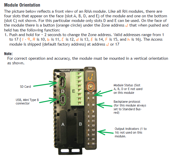
Watlow EZ-ZONE ® RMA (Access) module
Watlow EZ-ZONE ® RMA (Access) module
Product basic information and positioning
1. Core positioning
Watlow EZ-ZONE ® The RMA (Access) module is the functional extension core of the RM series controller, without independent PID control capability. It focuses on providing auxiliary functions such as multi protocol communication gateway, data recording, configuration backup, real-time clock, etc. It can be networked with RM modules such as RMC (controller), RME (extension), and RML (limit) to build a distributed control system with up to 17 modules (1 RMA+16 other RM modules), suitable for centralized monitoring and integration requirements of industrial heating, cooling, mixing and other processes.
2. Basic specifications
Category specific parameter description
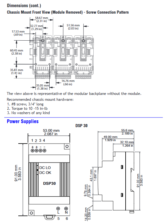
Appearance and installation 155mm (width) × 116.08mm (height), weight 453.59g DIN rail installation (EN50022 standard, 35 × 7.5mm), vertical installation required, top/bottom/front reserved 76.2mm maintenance space, optional panel installation (customer provided fasteners)
Power supply requirements: 20.4-30.8V AC/DC, frequency 50/60Hz, Class 2 or SELV certified power supply, power consumption 4W (active)/9VA (apparent), supporting Semi F47-0200 voltage drop standard (resistant to grid fluctuations)
Environmental adaptability working temperature -18~65 ° C, storage temperature -40~85 ° C 0-90% RH (non condensing), protection level IP20, required to be installed in NEMA Type 1 or above protective enclosure
Certification Standard UL ®/ EN 61010, Class 1 Div. 2 (optional), RoHS, WEEE partial models certified FM Class 3545 (limit control version), ANSI/ISA 12.12.01-2007 (hazardous area)
Warranty and Support: 3-year warranty (for first-time buyers, not for misuse/modification scenarios) Technical Support: Phone (+1 (507) 494-5656, CST 7:00-17:00), email( wintechsupport@watlow.com )Local representatives; Returns require prior application for RMA number
3. Product identification and version
Document version: Rev. B, released in March 2016, model example: RMAX-A3BD-AAA (including EtherNet/IP+Modbus TCP, SD card backup, data recording function)
Hardware version: distinguished by Serial Number, software version (S.rL), firmware version (S.bLd) and other information can be viewed in the Factory menu
Core functions and technical features
1. Communication function (core expansion capability)
(1) Support protocols and interfaces
The RMA module is the communication hub of the RM system, supporting multi protocol compatibility and adapting to different industrial network architectures
Protocol Type Interface Specification Key Parameters Applicable Scenarios
Modbus ® RTU EIA-485/232 addresses 1-247, baud rate 9600/19200/38400bps, verify None/Even/Odd, support high and low byte order configuration for small PLC/PC networking, low-cost remote monitoring
Modbus ® TCP Ethernet (10/100Mbps) supports DHCP/fixed IP, port 502, and can enable factory level Ethernet monitoring and cross regional data exchange simultaneously with EtherNet/IP
EtherNet/IP ™ Ethernet supports implicit (real-time I/O) and explicit (configuration/diagnostic) communication, with up to 100 implicit members integrated into Rockwell PLC for real-time control scenarios
DeviceNet ™ CAN bus node address 0-63, baud rate 125/250/500kbps, supports Quick Connect for fast online networking of field devices (sensors/actuators), low-cost distributed control
PROFIBUS DP EIA-485 addresses 0-126, supports DP-V0 (cyclic communication)/DP-V1 (non cyclic communication), 120 Ω terminal resistor Siemens PLC integration, high reliability industrial scenarios
USB Mini Type B (v1.1) is recognized as a storage device, used for SD card data export, configuration file read/write local debugging, and fast backup of log data
Standard Bus EIA-485 (default) is standard for all RM modules, used for inter module communication, supports 17 node RM series module networking, and shares power and configuration
(2) Communication Network Design Specification
Topology: EIA-485 adopts a daisy chain topology to avoid star/ring connections and reduce signal reflection; Ethernet needs to be connected through a switch and supports 10/100Mbps adaptation.
Distance limit: EIA-485 maximum 1200 meters (shielded twisted pair), EIA-232 maximum 15 meters, Ethernet maximum 100 meters (CAT5 and above cables).
Terminal resistor: The head and tail modules of the EIA-485 bus need to be connected to a 120 Ω terminal resistor to reduce signal attenuation; PROFIBUS DP supports switching between internal and external terminal resistors.
Anti interference measures: Communication lines and power lines should be wired separately (with a spacing of ≥ 10cm), using shielded twisted pair cables, and the shielding layer should be grounded at one end (grounding resistance ≤ 4 Ω).
2. Data Logging function
(1) Core competencies
Storage medium: Comes standard with a 2GB Micro SD card (supporting larger capacity), with CSV (comma separated values) file format, and can be opened directly with Excel or Notepad.
Record range: up to 200 log points, supporting analog inputs (temperature/current), alarm status, process values, set points, and other data sources.
Record parameters:
Cycle: Adjustable from 1-3600 seconds (default 10 seconds), supports event triggering (such as alarms, digital input signals).
Full storage strategy: "Stop" or "Overwrite" (overwrite older data, leaving 1.5MB of free space).
Timestamp: Dependent on Real Time Clock (RTC), supports HH: MM/HH: MM: SS time format, MM/DD/YYYY/DD/MM/YYYY date format.
(2) Configuration steps (taking RUI operation as an example)
Go to Setup → Data Logging Menu, set Period and Full Action.
Enter the Log Point Menu and configure the Source Function (data source, such as Analog Input), Source Zone (module address), and Display Precision (recording accuracy, such as 0.1/0.01) for each log point.
Startup record: The log file is automatically named by date/time (such as LOG_20241001_1430. csv) through Function Key, numerical input, or software triggering.
Data export: Connect to a PC via USB to read an SD card, or directly remove the SD card and export it using a card reader.
(3) Log file structure
Example Explanation of Column Name Content
Date 10/01/2024 Record date (format configurable)
Time 14:30:05 Record time (format configurable)
Analog Input 1 80.5 Analog Input 1 Value (Unit: ° F/° C)
Alarm 1 State On (On/Off)
Process Value 79.8 Process Value (such as temperature)
3. Configure backup and recovery functions
(1) Backup Capability Grading
The RMA module provides two modes of backup: basic backup and enhanced backup, depending on the model:
Backup type, storage location, support module quantity, applicable scenarios
Basic backup module with up to 4 RM modules (including 2 modules with Ramp/Soak function) built-in memory for small systems without SD card scenarios
Enhance backup of Micro SD card up to 16 RM modules (any RM series) for large systems, batch configuration cloning
(2) Backup and recovery operations
Backup process:
Go to Setup → Backup Menu, select Save (immediate backup) or Auto Backup (automatic backup during module replacement).
Select backup range: single zone (module) or all zones, enhanced version automatically stored to SD card (path:/CONFIG/Backup/Zone1. bak).
Recovery process:
Go to Setup → Backup Menu, select Restore → Now (restore immediately) or Change (automatically restore when module is replaced).
Confirm that the module address matches the model (with the same Part Number), and restart the module to take effect after recovery.
(3) Precautions
Backup content: including module parameters (input/output configuration, control algorithm, alarm threshold), excluding User Set 1/2 custom parameters and communication protocol assembly.
Recovery restriction: Only supports recovery of modules of the same model, different Part Number modules cannot be recovered (such as RMC and RME not interchangeable).
4. Real time clock (RTC) function
(1) Core role
Timestamp: Provides precise time reference for data recording and program (Profile) operation, supports time preservation after power interruption (battery backup).
Program Continuation: In conjunction with the Profile function of the RMC module, set the Power Off Time (program continuation time after power failure). When the power failure is ≤ the set time, the program will automatically resume running after power is restored; Terminate the program at timeout.
(2) Configuration and maintenance
Time configuration: Go to Setup → Real Time Clock Menu, set the hour (0-23), minute (0-59), date (1-31), year (2008-2100), and support switching between 12/24 hour clock.
Battery maintenance: BR1225 3V lithium battery is used, with a typical range of 3 years (in power-off state). After the battery is depleted, it needs to be replaced (power-off operation to avoid short circuit).
5. Security and Permission Management
(1) Access control
Password grading: Supports two levels of passwords: User and Administrator. The User password is used for regular operations, while the Admin password is used to modify security settings.
Rolling password: After enabling (Factory → Lock Menu → Rolling Password), the password will automatically change after power failure. The current password needs to be calculated using the Public Key (formula: User password=(pas. u × Code) Mod 929+70); Admin password=(pas. a × Code) Mod 997+1000.
(2) Adaptation to hazardous areas
Class 1 Div. 2 (optional): Only applicable to modules ending in "12" at the end of the model, temperature code T4, requires explosion-proof certified components, and is prohibited from use in Class 1 Div. 1 areas.
Wiring safety: Certified switches (such as explosion-proof types) should be used in hazardous areas, and live plugging and unplugging of wires is prohibited to avoid arcing.
Installation and Wiring Guide
1. Installation process
(1) Physical installation (DIN rail)
Guide rail preparation: Confirm that the guide rail meets the EN50022 standard (35 × 7.5mm), clean the surface of the guide rail, and ensure that there is no oil or rust.
Module fixation:
Insert the module from the hook above the guide rail, rotate the module to a vertical position, and hear a "click" sound to indicate that the buckle is locked.
When installing multiple modules, horizontally splice the modules to ensure complete contact of the backplane connectors, and check the flatness of the last module after installation.
Maintenance space: Reserve ≥ 76.2mm space at the top/bottom/front of the module for easy wiring and heat dissipation, avoiding direct contact with heating devices (such as heaters).
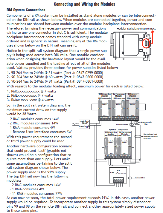
(2) Split Rail Installation
Applicable scenario: The module needs to be deployed remotely (such as separating the control room from the site), connecting two rails through an Inter module Bus with a maximum distance of 200 feet.
Wiring requirements: Use shielded twisted pair cables (CAT5 and above), connect terminals CX/CY/CZ (Slot C), ground the shielding layer at one end, and provide independent power supply (to avoid voltage drop).
2. Wiring specifications
(1) Terminal definition and limitations
Terminal specifications: Supports 12-30 AWG single/multi strand copper wire, with a torque of 0.56 Nm (right angle terminal)/0.5 Nm (front terminal), and a stripping length of 7.6mm (0.3 inches).
Core terminal functions (Slot C is the common terminal, Slot E is the protocol terminal):
Terminal group functional wiring requirements
Slot C (98/99) power input 98+, 99-, AC/DC polarity should be distinguished and reverse connection is prohibited
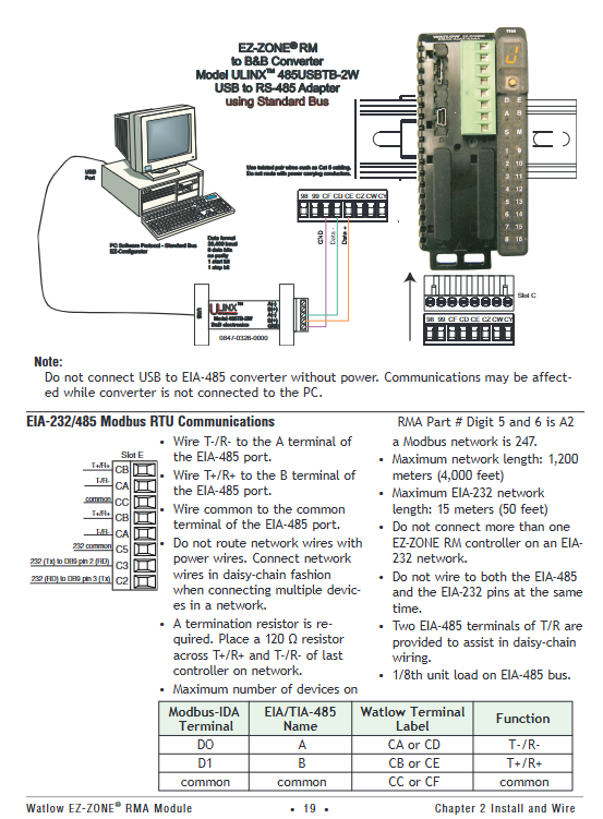
Slot C (CF/CD/CE) Standard Bus CF=Common Terminal, CD=T-/R-,CE=T+/R-, Using chrysanthemum link lines
Slot E (E1-E8) Ethernet E1=TX+, E2=TX -, E3=RX+, E6=RX -, wired in T568B sequence
Slot E (CA/CB/CC) Modbus RTU CA=T -/R -, CB=T+/R+, CC=common terminal, supports EIA-485/232 switching
(2) Safety wiring requirements
Electrical isolation: Analog input 1, digital I/O, and DC switch output need to be electrically isolated from process output to prevent grounding loops (grounding resistance ≤ 4 Ω).
Dangerous area wiring: Class 1 Div. 2 areas require certified wires (such as UL 1015) with terminal tightening torque ≥ 0.56 Nm to avoid loosening and sparking.
Power protection: It is recommended to connect a 1A slow melting fuse in series with the power input terminal to prevent overload damage to the module (recommended model: Littelfuse 0215001. MXP).
3. Typical System Networking Example
(1) Single rail PLC integration (Modbus RTU)
Composition: 1 RMA (gateway)+2 RMCs (controllers)+1 RME (extensions), PLC controlled through Modbus RTU.
Wiring: The slot E (CA/CB/CC) of RMA is connected to the EIA-485 port of PLC, and RMA is connected to other RM modules through the backplane bus. The power supply is connected to a 24V DC Class 2 power supply.
Configuration: RMA Modbus address=1, RMC address=2/3, RME address=4, PLC reads the process value of RMC through Modbus registers (address=2500+offset).
(2) Track Ethernet monitoring (EtherNet/IP)
Composition: Rail 1 (RMA+RMC x 2), Rail 2 (RME x 3), connected via Inter module Bus, monitored by PC via EtherNet/IP.
Wiring: RMA's Slot E (E1-E8) is connected to an Ethernet switch, and the CX/CY/CZ terminals of rails 1 and 2 are connected with shielded twisted pair cables. Each rail is independently powered (60W power supply).
Configuration: RMA fixed IP=192.168.1.10, PC IP=192.168.1.20, monitoring the status of all modules through EZ-ZONE Configurator software.
Operation and Configuration Guide
1. Menu navigation (based on RUI)
The RMA module is operated through the Remote User Interface (RUI, optional accessory) or software (EZ-ZONE Configurator), and the menu is divided into three levels:
Menu level entry method core function
Press and hold the Up+Down button for 3 seconds in Operations to display "oPEr" monitoring data log status, backup progress, and real-time clock
Long press the Up+Down button for 6 seconds to display "SEt" for configuring communication parameters, data recording, backup, etc RTC
Factory: Press and hold the Advance+Infinity keys for 6 seconds for security settings (password, permissions) and diagnostics (software version, IP address)
(1) Common operation examples (data recording startup)
Go to Operations → Data Logging Menu to view Available Memory and Available Time.
Enter Setup → Data Logging Menu, set Period=60 seconds, Full Action=Overwrite。
Enter Setup → Log Point Menu → Log Point 1, set Source Function=Analog Input, Source Zone=2 (RMC address), Display Precision=0.1。
Press Function Key (preset as "Start Log") to start the log, and RUI will display "Logging Active".
2. Software Configuration (EZ-ZONE Configurator)
(1) Software installation and connection
Download: Download EZ-ZONE Configurator (free) from the Watlow official website, supporting Windows 7 and above systems.
Connection: Connect to RMA's Standard Bus terminal (CF/CD/CE) through a USB-EIA-485 converter, and the software automatically scans for RM modules in the network.
(2) Core configuration steps (Modbus TCP setup)
Select the RMA module, enter the "Communications" tab, and set IP Address Mode=Fixed,IP=192.168.1.10,Subnet=255.255.255.0,Gateway=192.168.1.1。
Enable "Modbus TCP Enable" and "EtherNet/IP Enable", set Modbus Port to 502.
Go to the "Gateway" tab, enable Gateway Instance 1-4 (corresponding to RM module addresses 1-4), and set Modbus Offset=0 (no address offset).
Click "Save" to save the configuration, restart RMA to take effect, and verify network connectivity through Ping command.
3. Communication testing tools
Modbus RTU Test: Use Watlow Modbus RTU Diagnostic Tool (free), set baud rate=9600, address=1, read register 2500 (process value), verify communication is normal.
EtherNet/IP testing: Using Rockwell RSLogix software, add EtherNet/IP driver for RMA module, read implicit assembly (Input Assembly=1, Output Assembly=2), and verify data interaction.
Maintenance and troubleshooting
1. Daily maintenance
(1) Regular inspection (monthly)
Appearance inspection: Check if the module indicator lights (Power, Comm) are normal and there are no errors (red light constantly on=fault).
Wiring inspection: The terminals are not loose or oxidized, the shielding layer is well grounded, and there is no parallel wiring between the communication line and the power line.
SD card check: Check if the SD card is in place, with a remaining space of ≥ 10%, and regularly export logs (to avoid stopping recording when full).
(2) Annual maintenance
Power test: Use a multimeter to measure the power supply voltage (20.4-30.8V), with ripple ≤ 5%, to ensure stable power supply.
Communication test: Use diagnostic tools to verify that all protocol communication is normal, Modbus response time ≤ 100ms, Ethernet packet loss rate=0.
Battery check: Check if the RTC time is accurate, and replace the battery (BR1225) if the deviation is greater than 5 minutes.
2. Troubleshooting
(1) Common faults and solutions
Possible causes of malfunction, troubleshooting steps, and solutions
Module has no display, power supply is not connected, voltage is abnormal, module fault 1. Measure the voltage at terminal 98/99; 2. Check the fuse (if any); 3. Observe if the Power light is on. 1. Reconnect the wiring; 2. Replace the power supply; 3. Apply for RMA repair
Communication failure (Modbus) address/baud rate mismatch, wiring error, terminal resistance not connected 1. Check RMA and PLC parameters; 2. Check the CA/CB/CC wiring; 3. Measure bus voltage (2.5-5V) 1. Unified parameters; 2. Correct the wiring; 3. Connect a 120 Ω resistor at the beginning and end
Data recording does not start. SD card is not inserted/damaged, and log points are not configured. 1. Check if the SD card is recognized (Operations → Data Logging → Status); 2. Check the Log Point configuration. 1. Replace the SD card; 2. Reconfigure log points
Backup failed, memory/SD card full, module address conflict. 1. Check Available Memory; 2. Check if the Zone address is duplicated. 1. Clean up the storage; 2. Modify duplicate addresses
Ethernet unresponsive IP conflict, network cable failure, switch abnormality 1. Check if the IP is occupied; 2. Test the continuity of the network cable; 3. Check if the Link light is on. 1. Replace the IP address. 2. Replace the network cable; 3. Restart the switch
(2) Meaning of indicator lights
Meaning of indicator light status
Power (green) is constantly on, and the power supply is normal
Power (red) constantly on, abnormal power supply (overvoltage/undervoltage)
Comm (green) flashing communication active
Comm (red) constantly on communication fault (address/parameter error)
SD Card (green) flashing SD card read/write in progress
SD Card (red) constantly on SD card fault (unrecognized/damaged)
3. View fault logs
Enter Factory → Diagnostics Menu to view information such as Software ID, Serial Number, IP Actual Address, etc. Record Error Code (such as "E01=communication failure") when there is a fault for technical support to troubleshoot.
Typical application scenarios
1. Temperature control and monitoring of industrial ovens
System composition: 1 RMA (EtherNet/IP Gateway)+2 RMCs (Temperature Control)+1 RME (Digital I/O Expansion), with PC monitoring via Ethernet.
Function implementation:
RMC controls oven heating, RME collects door switch status, RMA records temperature data (1 record every 60 seconds, stored on SD card).
PC can view the temperature curve in real-time through EZ-ZONE Configurator, and trigger an email alarm (EtherNet/IP linkage) in case of abnormalities.
2. Backup of semiconductor process equipment configuration
System composition: 1 RMA (Enhanced Edition)+4 RMCs (Process Control) for semiconductor wafer heat treatment equipment.
Function implementation:
RMA regularly backs up the configuration of 4 RMCs (automatically backed up to SD card every morning), and automatically restores the configuration when replacing RMCs to reduce downtime.
Upload process parameters to MES system through Modbus TCP to achieve production data traceability.
3. Equipment monitoring in hazardous areas (Class 1 Div. 2)
System composition: 1 RMA (Class 1 Div. 2 certification)+1 RML (limit control), used for temperature monitoring of chemical reaction vessels.
Function implementation:
RML monitors the temperature of the reactor and triggers an RMA alarm output when it exceeds the limit, cutting off the heating power supply; RMA uploads data to the explosion-proof PLC via Modbus RTU.
Explosion proof junction boxes are used, and armored shielded wires are used for communication lines, meeting Class 1 Div. 2 safety requirements.
Ordering Information
Taking "RMAX-A3BD-AAA" as an example, the meaning of each segment of the model:
Field meaning optional values
RM Product Series (Rail Mount)-
Type of Module A (Access)-
X connector type A=right angle terminal, F=front terminal
A3 communication protocol A2=Modbus RTU, A3=EtherNet/IP+Modbus TCP, A5=DeviceNet
Option B=RTC+battery, D=data recording+SD card
D Backup Capability A=Basic Backup (4 modules), B=Enhanced Backup (16 modules)
AAAA custom option 0000=standard, 12=Class 1 Div. 2
- OMRON
- ABB
- General Electric
- EMERSON
- Honeywell
- HIMA
- ALSTOM
- Rolls-Royce
- MOTOROLA
- Rockwell
- Siemens
- Woodward
- YOKOGAWA
- FOXBORO
- KOLLMORGEN
- MOOG
- KB
- YAMAHA
- BENDER
- TEKTRONIX
- Westinghouse
- AMAT
- AB
- XYCOM
- Yaskawa
- B&R
- Schneider
- KONGSBERG
- NI
- WATLOW
- ProSoft
- SEW
- ADVANCED
- Reliance
- TRICONEX
- METSO
- MAN
- Advantest
- STUDER
- DANAHER MOTION
- Bently
- Galil
- EATON
- MOLEX
- DEIF
- B&W
- ZYGO
- Aerotech
- DANFOSS
- Beijer
- Moxa
- Rexroth
- Johnson
- WAGO
- TOSHIBA
- BMCM
- SMC
- HITACHI
- HIRSCHMANN
- Application field
- XP POWER
- CTI
- TRICON
- STOBER
- Thinklogical
- Horner Automation
- Meggitt
- Fanuc
- Baldor
- SHINKAWA
- Other Brands
- UniOP
- KUKA
- Iba
- Beckhoff
-
 Basler DECS-100-B15 Digital AVR
 -
 Basler 9284900103 PS DECS-400N
 -
 Basler D4N3H1U Intertie Protection
 -
 Basler DECS-100-B15 A15 AVR
 -
 Basler KR4F Voltage Regulator
 -
 Basler BE26434 T14 Transformer
 -
 Basler SR8A-2B15B3A Regulator
 -
 Westinghouse 774B472A12 AR Relay
 -
Basler DECS-100-B15 AVR
-
 Basler XR2002F Regulator 110V
 -
 Basler SR125-E Static Regulator
 -
 Basler SSR 125-12 Regulator
 -
 Basler MOC2599 Motor Pot
 -
 Basler BE1-DFPR Feeder Relay
 -
 Basler CBS 305 Current Boost
 -
 Basler BE1-25 AutoSync
 -
 Basler MVC 300 Voltage Control
 -
 Basler BE3-25A AutoSync
 -
 Basler KR7FF Static Regulator
 -
 Basler 90-49000-100 Regulator
 -
 Basler 880 kVA Dry Type Transformer Specs
 -
 Basler Electric BE1-25 Sync-Check Relay Specs
 -
 Basler SSR 125-12 Voltage Regulator Specs
 -
 Basler Electric BE1-851 Overcurrent Relay Review
 -
Basler Electric 149D930G02 Control Sub-Assembly
-
 Basler Electric BE1-81O/UT Frequency Relay Specs
 -
 Basler Electric BE1-51/27C Overcurrent Relay
 -
 Basler Electric 149D956G02 Industrial Component
 -
Basler Electric BE1-51A Overcurrent Relay Specs
-
 Basler Electric BE1-40Q Loss of Excitation Relay
 -
 Basler DECS-200 Excitation Control System
 -
 Basler DECS-200 Voltage Regulator 56-277V AC / 125V DC
 -
 Basler BE1-87T Transformer Differential Relay
 -
 Basler RDP-110-S1 Protection Relay
 -
 Basler BE1-700V Digital Protective Relay
 -
 Basler BE1-951 Overcurrent Protection System
 -
 Basler DECS-300 Digital Excitation Control
 -
 Basler DECS-200 Digital Excitation Control
 -
 Basler DECS-200-1C Excitation Control System
 -
Basler DECS-200-1L Digital Excitation Control
-
 Basler Electric BE1-GPS Generator Protection System
 -
Basler Electric DECS-200-1C Digital Excitation Controller
-
 Basler Electric DECS125-15 Excitation Control with Power Module
 -
 Basler Electric BE1-87G Differential Relay
 -
 Basler Electric BE1-11 Protection System I5A3M2P2N0EA00
 -
Basler Electric DECS-200-1C Excitation Control System
-
Basler Electric BE1-11g Generator Protection Relay
-
 Basler Electric DECS 125-15-B2C1 V2.0.9 Excitation Control
 -
 Basler Electric BE1-81O/UT3ED1JA7N2F Frequency Relay
 -
Basler Electric BE1-81O/UT3EE1YB7N1F Frequency Relay
-
 Basler Electric DECS-200-1L Digital Excitation Control System
 -
Basler DECS125-15-B2C1 Excitation Control
-
 Basler 9507900205 SSR Retrofit Voltage Regulator
 -
 Basler BE2000E Digital Voltage Regulator
 -
 Basler BE1-GPS Generator Protection System
 -
Basler DECS-250-CN1CN1N Digital Excitation Control
-
 Basler DGC-2020 Genset Controller
 -
 Basler BE1-81O UT3ED1LA7N0F Frequency Relay (Variant)
 -
 Basler BE1-81O UT3EE1YA9S0F Frequency Relay (Variant)
 -
Basler BE1-81O Over/Under Frequency Relay
-
Basler DECS125-15 Digital Excitation Control
-
Basler Electric BE1-951 Overcurrent Protection System
-
 Basler Electric BE1-700V Digital Protective Relay
 -
 Basler Electric APR63-5 Automatic Voltage Regulator
 -
Basler Electric BE1-851 Overcurrent Protection System
-
Basler Electric DECS-250-LN1SN1N Excitation Control
-
 Basler Electric BE1-87T Transformer Differential Relay
 -
Basler Electric DECS-200-1L Excitation Control System
-
 Basler Electric 9310300100 DECS-300 Excitation Control
 -
 Basler Electric SSE-N 125-4.5KW Shunt Exciter Regulator
 -
 Basler Electric DGC-2020HD-5NS1DNSBA Genset Controller
 -
Basler Electric BE1-81-O/UT3EE1JB7N1F Frequency Relay
-
Basler Electric BE1-81T1EE1WA0N1F Frequency Relay
-
 Basler Electric BE1-25M1EA6PN5R1F Sync-Check Relay
 -
 Basler Electric BE1-GPS Generator Protection System
 -
Basler Electric DECS-250-LN1SN1N Excitation Control Rev V
-
 Basler Electric DECS-250-CN2CN1N Excitation Control
 -
Basler Electric BE1-50/51B-207 Overcurrent Relay
-
Basler Electric DECS-300-C0N0 Excitation Control System
-
Basler Electric DECS-200 Digital Excitation Control System
-
Basler Electric DECS-250-LN1CN1N Excitation Unit
-
Basler Electric DECS-250 LN2SA1D Excitation Unit Specs
-
Basler Electric BE1-87T Transformer Relay Review
-
Basler Electric BE1-11 Protection System
-
Basler Electric BE1-GPS100-E4N1H1N Protection System
-
 Allen-Bradley 442G-MABH-R Safety Module
 -
 Beckhoff CX1030-0111 PLC Assembly Profile
 -
 FANUC IC693CPU364 PLC Module
 -
 Orange Denmark Type 200816 220 PLC Specs
 -
 OMRON C200H-SNT31 Sysmac PLC Module
 -
 Allen Bradley 20AB022A3AYNANC0 PowerFlex 70
 -
 OMRON C200HW-PCU01 Position Control Unit
 -
 ABB AO845A-eA Analog Output Module
 -
 OMRON CJ1M-CPU22 CPU Unit
 -
 Allen Bradley 100-E265ED11 Contactor
 -
 Honeywell 51304511-100 Interface Module
 -
 SOLEXY BXF3S0101N0018 Gateway Module
 -
 OMRON CJ2H-CPU65 CPU Unit
 -
 Automation Direct GS2-45P0 AC Drive
 -
 M68-2000 2-Axis Motion CNC Controller
 -
 OMRON CJ1M-CPU11 V3.0 PLC CPU Unit
 -
 OMRON CJ1W-NC413 4-Axis Positioning Controller
 -
 OMRON 3G2A3-PRO16 Programming Console HMI
 -
 Siemens 3VT8440-2AA04-2GA2 Molded Case Circuit Breaker
 -
 Siemens 3RT5045 Contactor Series
 -
 OMRON C200HS-CPU01-E SYSMAC PLC Controller
 -
 OMRON C500-NC103-E Positioning Control Unit
 -
 OMRON CJ1W-TC001 Temperature Control Unit
 -
 OMRON NJ301-1100 NJ-PA3001 PLC System EtherCAT
 -
 Pilz 773100 M1P Safety Relay Base Unit
 -
 Siemens SINUMERIK 840D SL NCU 720.3B with PLC 317-3 PN/DP
 -
 Siemens 6AV6618-7GD01-3AB0 HMI Panel
 -
 OMRON F150-C15E-3 Vision Mate Controller PLC Overview
 -
 Mitsubishi MELSEC A Series PLC System A63P A3ACPU A616AD A68RD3
 -
 M68-2000 2 Axis Motion Controller SCE SERVO CNC
 -
 OMRON FZ-S2M PLC Camera Vision System
 -
 VISOLUX SLVA-4K PLC Module from Elektronik GmbH
 -
 OMRON CJ1M-CPU23 V2.0 PLC CPU Unit
 -
 ABB AI86-16CHF PCB Card 5761751-9 B Specifications
 -
 Allen-Bradley 100-D140ZJ22L Contactor Overview
 -
 Merlin Gerin PB80 PLC Rack
 -
 WEIR WE203 Power Supply PLC
 -
 OMRON NX-TS3102 Temperature Input Unit
 -
 Siemens 6ES7146-6FF00-0AB0 I/O Module
 -
 Fanuc A16B-3300-0057 Circuit Board
 -
 OMRON CJ1W-IDP01 Input Module
 -
 Siemens 6FX2007-1AD13 Handheld Unit
 -
 Gems EM54 PLC Module PCB


