
YASKAWA Z1000 series HVAC dedicated frequency converter
YASKAWA Z1000 series HVAC dedicated frequency converter
Applicable models:
200V level: 2.2~110kW (3~150HP);
400V level: 2.2~370kW (3~500HP);
Model identification: CIMR-ZU A series.
Core positioning: A practical guide for engineering and technical personnel, covering the entire process from parameter initialization, motor debugging to troubleshooting, supporting multiple modes such as V/f control and PM motor open-loop vector control, and adapting to the dynamic adjustment needs of HVAC systems.
Core functional framework
The document revolves around three core modules: parameter configuration, function implementation, debugging and maintenance. The core modules include parameter details, regular inspection and maintenance, and communication protocol configuration (BACnet/APOGEE FLN/Metasys N2/EMOBU/Modbus), forming a complete closed loop of "setup run monitoring maintenance".
Core parameter configuration (classified by functional modules)
1. Initialize parameters (Group A)
The core is used for initial driver settings, including basic configurations such as language, control mode, parameter reset, etc.
A1-00 (Language Selection): Supports English, Japanese, French, Spanish, Portuguese, and does not reset this parameter during initialization.
A1-02 (Control mode selection): 0 (Induction motor V/f control, speed range 1:40), 5 (PM motor open-loop vector control, speed range 1:20).
A1-03 (Parameter Initialization): Supports multiple initialization modes such as user-defined, 2-wire/3-wire control, HVAC dedicated, OEM bypass, etc., and automatically returns to 0 after reset.
A1-04/A1-05 (password setting): A1-05 hides the parameter setting password, A1-04 unlocks by entering the password, and restricts the modification permission of core parameters (such as A1-01~A1-03).
2. Application Function Parameters (Group B)
Focus on core application functions such as operating mode, braking, speed search, PI control, etc., and adapt to HVAC load characteristics.
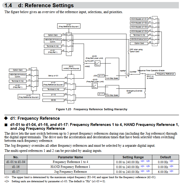
(1) Operation mode selection (b1 group)
B1-01 (AUTO mode frequency source): Supports four input methods: HOA keyboard, analog terminal, communication, and tab.
B1-02 (AUTO mode operation command): Optional control terminals, communication, and tab triggers. Selecting 3 when no tab is installed will trigger the oPE05 error.
B1-03 (stop mode): 0 (slope stop), 1 (free stop), 2 (DC injection brake stop), 3 (free stop with delay).
(2) PI control (b5 group)
Specially designed for closed-loop control of pressure, flow, and temperature in HVAC systems, with core parameters:
B5-01 (PI function enabled): 0 (disabled), 1 (PI output directly as frequency command), 3 (PI output combined with frequency command).
B5-02/B5-03 (Proportional/Integral Parameters): Proportional gain of 0.00~25.00, integration time of 0.0~3600s, can suppress overshoot or accelerate response speed.
B5-12 (PI feedback loss detection): Supports low/high feedback detection, can set alarms, faults, or only output signals to avoid sensor failures causing system loss of control.
(3) Energy saving function (b8 group)
B8-01 (Energy saving control enable): When enabled, automatically optimize the motor operating voltage to improve light load efficiency. PM motors should be used with caution.
3. Motor parameters (Group E)
The core parameter configuration covering induction motors and PM motors directly affects control accuracy.
E1 group (V/f mode setting): E1-03 selects V/f curve (15 presets+1 customization), suitable for constant torque, variable torque (fan/pump), high starting torque and other scenarios.
E2 group (induction motor parameters): requires input of motor rated current (E2-01), rated slip (E2-02), no-load current (E2-03), etc., supporting automatic tuning and automatic acquisition.
E5 group (PM motor parameters): Only visible when A1-02=5, stator resistance (E5-05), d/q-axis inductance (E5-06/E5-07), induced voltage constant (E5-09/E5-24), etc. need to be set.
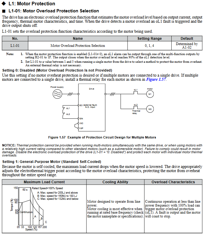
4. Protection function parameters (L group)
Comprehensively ensuring the safety of drivers, motors, and systems, with core components including:
Motor protection (L1 group): L1-01 selects overload protection type (general motor/PM motor), supports PTC thermistor connection (L1-03~L1-05) to detect motor temperature.
Power protection (L2 group): L2-01 is configured with instantaneous power failure response strategy, and L2-05 is set with undervoltage detection level (default 190V for 200V level, default 380V for 400V level).
Lock rotor protection (L3 group): Install lock rotor protection during acceleration, deceleration, and operation to avoid motor overload or overvoltage faults.
Fault restart (L5 group): L5-01 sets the number of automatic restarts (0-10 times), supports automatic recovery after overcurrent, overload, overvoltage and other faults, and the lifting application is disabled.
5. Terminal functional parameters (H group)
Configure digital/analog input/output terminals to achieve external signal interaction.
H1 group (digital input): 7-channel programmable terminals (S1~S7), supporting functions such as forward and reverse rotation, multi-stage speed, fault reset, emergency stop, etc., and can be configured with 2-wire/3-wire control logic.
H2 group (digital output): 3 relay outputs (M1-M2/M3-M4/M5-M6), which can map signals such as operating status, zero speed, fault, and consistent speed.
H3 group (analog input): 2 analog terminals (A1/A2), supporting 0~10V/4~20mA signals, configurable frequency command, PI feedback, torque detection level and other functions.
H4 group (analog output): 2 analog terminals (FM/AM), capable of outputting monitoring data such as frequency, current, power, etc., supporting gain/bias adjustment.
6. Communication parameters (H5/F6/F7 group)
Supports multiple industrial communication protocols and is compatible with building automation system integration.
Core protocols: BACnet, APOGEE FLN, Metasys N2, MEMOBU/Modbus;
Basic configuration: H5-01 (slave address), H5-02 (baud rate), H5-03 (checksum), which need to be unified with the upper computer;
Fault handling: F6-01 configuration communication fault driver behavior (shutdown/continue running/alarm).
Motor debugging (T group)
Obtain precise motor parameters through automatic tuning to ensure control performance.
1. Induction motor debugging (T1 group)
T1-01 selects tuning mode: 2 (static resistance detection), 3 (V/f energy-saving mode rotation tuning);
Pre input of motor rated power (T1-02), voltage (T1-03), current (T1-04) and other nameplate parameters is required, and after tuning, the E2 group parameters will be automatically updated.
2. PM motor debugging (T2 group)
T2-03 Select motor type (0=IPM motor, 1=SPM motor);
T2-18 starts tuning and automatically calibrates key parameters such as stator resistance, inductance, and induced voltage constant, ensuring that the motor is unloaded.
Monitoring parameters (U group)
Real time viewing of drive operation status, fault records, and maintenance information, core categories:
U1 group (operating status): output frequency (U1-02), output current (U1-03), DC bus voltage (U1-04), etc;
U2/U3 group (fault tracing): record parameter snapshots (such as current, frequency) and historical fault lists (up to multiple records can be stored) when faults occur;
U4 group (maintenance monitoring): cooling fan running time (U4-03), percentage of capacitor life (U4-05), pre charge relay life (U4-07), etc. If it is less than 20%, it needs to be replaced in advance;
U5 group (PI monitoring): PI set values, feedback values, output values, etc., facilitate closed-loop control optimization.
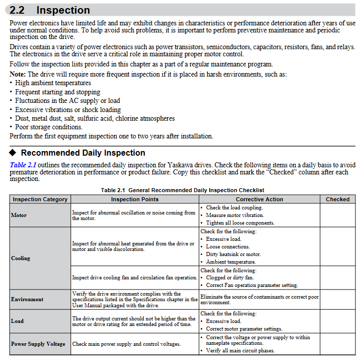
Regular inspection and maintenance
1. Safety regulations
After power failure, wait for the capacitor to discharge (DC bus voltage below 50V) before wiring or replacing components;
Do not remove the cover plate or touch the circuit board while it is powered on to avoid static electricity damaging the components.
2. Inspection cycle and content
(1) Daily inspection (daily)
Appearance: The driver/motor has no abnormal noise, odor, or vibration, and the cooling fan is running normally;
Display: No alarm code, stable parameters such as current and voltage;
Environment: Temperature (-10~+50 ℃), humidity (0~95% without condensation) meet the requirements, and there is no dust accumulation.
(2) Regular inspection (annually)
Electrical components: The wiring terminals are securely fastened, the insulation of the wires is not aged, the capacitors are not leaking or bulging;
Cooling system: The radiator is clean, the fan is not stuck, and the air duct is not blocked;
Function verification: No abnormal changes in parameters, protection functions (such as overload and overvoltage) triggered normally.
3. Replacement of vulnerable parts
Cooling fan: Replace it after running for 20000 hours or 5 years, and reset the o4-03 parameter after replacement;
HOA keyboard battery: The model is CR1220 lithium battery, with a lifespan of about 2 years. Replace it when "bAT" is displayed, and pay attention to the installation of the positive and negative poles;
Capacitors and relays: After 5-7 years of operation, the capacity/contact status needs to be checked, and if it is lower than 80% of the initial value, it should be replaced.
Communication Protocol Configuration (Core Protocol Summary)
1. MEMOBU/Modbus communication
Physical interface: RS-422/RS-485 (terminal R+/R -/S+/S -);
Core parameters: Slave address (H5-01:0~FFH), baud rate (H5-02:1200bps~115200bps), parity bit (H5-03: none/even/odd parity);
Function: Supports reading monitoring data, writing parameters, controlling start stop, and fault reset.
2. BACnet communication
Adapt to building automation systems and support BACnet MS/TP protocol;
Configuration parameters: F6-46 (baud rate), device object, analog input/output object mapping;
Function: Implement remote monitoring and control of the frequency converter by the upper computer, and support fault alarm uploading.
Compliance and Safety Tips
Safety level: Complies with UL 508C, CSA C22.2 No.14, CE LVD/EMC and other standards;
Prohibited scenarios: It is prohibited to use equipment that directly affects personal safety, such as medical, aviation, nuclear power, etc. The lifting application is disabled and automatically restarted due to malfunction;
Operation specifications: All wiring, parameter modification, and maintenance work must be carried out by authorized personnel, and the power-off discharge process must be strictly followed.
- OMRON
- ABB
- General Electric
- EMERSON
- Honeywell
- HIMA
- ALSTOM
- Rolls-Royce
- MOTOROLA
- Rockwell
- Siemens
- Woodward
- YOKOGAWA
- FOXBORO
- KOLLMORGEN
- MOOG
- KB
- YAMAHA
- BENDER
- TEKTRONIX
- Westinghouse
- AMAT
- AB
- XYCOM
- Yaskawa
- B&R
- Schneider
- KONGSBERG
- NI
- WATLOW
- ProSoft
- SEW
- ADVANCED
- Reliance
- TRICONEX
- METSO
- MAN
- Advantest
- STUDER
- DANAHER MOTION
- Bently
- Galil
- EATON
- MOLEX
- DEIF
- B&W
- ZYGO
- Aerotech
- DANFOSS
- Beijer
- Moxa
- Rexroth
- Johnson
- WAGO
- TOSHIBA
- BMCM
- SMC
- HITACHI
- HIRSCHMANN
- Application field
- XP POWER
- CTI
- TRICON
- STOBER
- Thinklogical
- Horner Automation
- Meggitt
- Fanuc
- Baldor
- SHINKAWA
- Other Brands
- UniOP
- KUKA
- Iba
- Beckhoff
-
 OMRON C60H C6DR DE V1 Sysmac PLC
 -
 MITSUBISHI ELECTRIC A2ACPU21 S1 CPU Module
 -
 ABB BAILEY INNPM12 Network Process Module
 -
 HONEYWELL 620 0073C IPC PLC Module
 -
 Mitsubishi 15050 PR02B PLC Circuit Board
 -
 SIEMENS 6SY7000 0AC37 Drive Control Module
 -
 OMRON TJ2 ECT16 Traxial EtherCAT Controller
 -
 GE Fanuc IC698PSD300D Power Supply Module
 -
 Texas Instruments Series 505 16 Position Base
 -
 OMRON YASKAWA SGDH 10DE OY Servo Drive
 -
 Allen‑Bradley 440G-MT Safety Interlock Switch Specs
 -
 Rubycon PD27A 24V 8A Power Supply Module
 -
 SK-H1-GDB1-F11D PLC Gate Driver Board Kit
 -
 VIPA 441-4UA14 451-4UA14 PLC Module Rack
 -
 Mitsubishi FX5U-80MT ESS PLC Controller Specs
 -
 Mitsubishi Q64TCRTN Temperature PLC Module
 -
 GE 1C31170G Rev10 PLC Circuit Board Module
 -
 Schneider TWDLMDA40DTK PLC Controller Module
 -
 Omron FQM1-MMA22 Motion Control Module Specs
 -
 OMRON CJ1W-NCF71 Position Control Unit Specs
 -
 Schneider TSXETY4103 Ethernet Module
 -
 Mitsubishi Q12PHCPU Process CPU
 -
 Yaskawa 3G3HV-A4022-CE AC Drive
 -
 Cincinnati Milacron 3-533-0669G Temperature Control Board
 -
 Allen Bradley 20AC030A3AYNANC0 PowerFlex 70 Drive
 -
 Siemens 6ES7314-6BG03-0AB0 CPU 314C-2 DP
 -
 Carrier 17EX54007903 PLC Module
 -
 OMRON CS1W-V600C12 ID Controller Module
 -
 Honeywell 51402755-100 PCB Card
 -
 Heidenhain ECN 113 Rotary Encoder
 -
 OMRON B7AM-8B16 I/O Terminal Block
 -
 Fanuc A06B-6110-H026 Power Supply Module
 -
 Schneider TSXETG3021 Ethernet Gateway
 -
 OMRON CS1W-CLK21-V1 Controller Link Unit
 -
 NP1W6406T-Z704 PLC I/O Module
 -
 OMRON CJ1W-DA08C Analog Output Module
 -
 Yaskawa 3G3HV-A4022-CE AC Drive
 -
 OMRON NB7W-TW01B CP1L-EL20DR-D Power Panel
 -
 OMRON C500-NC103-E Position Control Unit
 -
 Steag Hamatech PLC DCS Servo Control System
 -
 Siemens 6SN1123-1AA00-0DA1 Power Supply Module
 -
 GE IC693CHS391H CPU & AD693CMM301A PLC Module
 -
 Siemens 6FC5303-0AF23-1AA1 PLC Control Panel
 -
 Square D CM4000T PowerLogic Circuit Monitor J1 F16
 -
 Siemens 6FX5002-5DG10-1BA0 MOTION-CONNECT 500 Cable
 -
 Schmersal SRB324ST 101195504 Safety Relay 24V
 -
 Mitsubishi 15050-PR02A PLC Circuit Board Module
 -
 OMRON CQM1-AD041 Analog Input PLC Module
 -
 Beckhoff EL5042 EtherCAT PLC Terminal Module
 -
 OMRON C200HW-MC402-E Motion Control Unit
 -
 C36TC0UA1100 Industrial Temperature Controller
 -
 NL8048BC24 12 Industrial Control LCD Module
 -
 OMRON R88D Servo Drive and Motor System
 -
 OMRON CS1W CLK21 V1 Controller Link Module
 -
 OMRON YASKAWA R7M A20030 S1 D Servo Motor
 -
 SIEMENS 6AV2128 3KB06 0AX1 Unified Comfort Panel
 -
 Schneider Electric METSEPM8240 PowerLogic Meter
 -
 Advanced AMCI 1PLC 1 31F Programmable Limit Switch
 -
 ABB PM582 ETH Programmable Logic Processor
 -
 SIEMENS 6FC5110 0CB01 0AA0 CPU Control Board
 -
 Schleicher P03GS13A CPU Module
 -
 Siemens 6SN1123-1AA00-0BA1 Power Module
 -
 Mitsubishi A1S61PN Power Supply Module
 -
 Yaskawa CPS-IONB DC Power Supply Module
 -
 Siemens 6ES7215-2BD00 CPU 215-2
 -
 Mitsubishi A2ACPU MELSEC PLC System Kit
 -
 ProSoft 3150-MCM Communication Module
 -
 Mitsubishi OSE104ET Incremental Encoder
 -
 OMRON CJ1W-AD081-V1 Analog Input Module
 -
 Broadcom BCM5464A1KRB Quad Port Ethernet IC
 -
 Modicon M221-24IO TM221C24 PLC 24 PNP Transistor
 -
 Allen-Bradley 1321-3R160-B Line Reactor 3R160B
 -
 Beckhoff CX1020-0012 Embedded PLC Module Specs
 -
 Turck BL20-PF-24VDC-D Power Feed Module Specs
 -
 Siemens 6SY7000-0AC37 Power Supply Module
 -
 Yaskawa SGDH-10DE-OY 1kW 400V Servo Drive Specs
 -
 Omron 3G3SV-BB015-E 1.5kW 220V VFD Specs
 -
 Uni-Pro CPU91-PLC J 23.020167X Processor Module
 -
 PASABAN MTC-3044 PLC Rack Power Supply 4835-A
 -
 XYCOM 3015T Operator Interface Panel BIN4.4.4
 -
 OMRON CJ1W-MD261 Mixed I/O Module
 -
 Omron NJ301-1100 PLC CPU eCat EIP Specs
 -
 Omron F500-C15-ETN Vision System PLC Module
 -
 Modicon M241-24IO TM/T2UK PLC with Ethernet
 -
 SIXNET YS-800-001 RTU PLC Module
 -
 BEMAC UST-202-D Interface Board 1307D V08B2
 -
 Yaskawa JANCD-MMOIC-02 Drive Circuit Board
 -
 ABB 3BSE005028R1 SDCS-COM-1 Comm Board
 -
 Omron 3G3MX2-A4110 A4150 Inverter Drives Specs
 -
 KEYENCE CA-E100 PLC Module
 -
 GE IC693ALG223-GB Analog Input Module Specs
 -
 ABB BAILEY IMMFP01 Multi Function Processor System
 -
 SIEMENS 6FC5372 0AA00 0AA1 NCU 7202 Controller
 -
Modicon TM241CE4 40I O Transistor Programmable Controller
-
 SIEMENS 6ES7 315 2EH13 0AB0 CPU 3152 PN DP
 -
 NORIS A1 91 PCB Card Rack Module System
 -
 SIEMENS 6ES7 313 5BE01 0AB0 Compact CPU
 -
 SCHNEIDER ELECTRIC S144B MICROLOGIC 60A Trip Unit
 -
 CNI PLC269 v3 Control Module Board Rev H
 -
ABB BAILEY IIMCP02 Processor Module
-
 OMRON NT20S ST121 EV3 Operator Interface Terminal
 -
 OMRON NS-CA001 Video Input Unit
 -
 GE Fanuc IC695CHS012 RX3i Backplane
 -
 Allen Bradley 2711E-K14C6 PanelView 1400e Terminal
 -
 Siemens Sinamics CCB 10000432.71 Power Cell
 -
 Siemens 6SL3210-1SE21-8UA0 Power Module PM340
 -
 Yaskawa CIMR-F7A20P4 AC Drive
 -
 Beckhoff EP1918-0002 EtherCAT Box I/O Module
 -
 OMRON CQM1-TC001 Temperature Control Module
 -
 GE Fanuc SGHA36AT0400 Industrial Contactor
 -
 OMRON NJ501-1500 PLC Machine Automation Controller
 -
 Mitsubishi MAZAK QX084 Power Supply MELDAS 500 CNC
 -
 B&R 0AC808.9 PLC Automation Module
 -
 OMRON CP1H-XA40DT1-D PLC Module
 -
 G&W Electric PLC15 5111 011 15kV Capnut Assembly
 -
 GE DS200SLCCG3AGH PCB Circuit Board
 -
 Siemens SINUMERIK 6FC3981-4FD PLC Extension
 -
 OMRON F300-DC I/O Image Processing Unit
 -
 FANUC A06B-0314-B002 AC Servo Motor
 -
 GC-S84 Programmable Controller Logic Module
 -
 PASABAN MONTELEC MTC3001-DC Drive Control PLC
 -
 Allen Bradley 100E460EJ11 Auxiliary Contactor
 -
 Bosch Rexroth 1070075337-101 Card Parameters
 -
 HMS Anybus AB7646-F Gateway Specifications
 -
 Bosch 062633-303401 CNC Servo PLC Card
 -
 TI 500-5023 Series PLC Power Supply
 -
 Siemens C98043-A7002-L1-12 Circuit Board
 -
 Omron E5CC-RX3A5M-000 Controller


