
Westinghouse iGen4500DFc Dual Fuel Digital Variable Frequency Generator
Westinghouse iGen4500DFc Dual Fuel Digital Variable Frequency Generator
Core parameters and positioning of the product
1. Basic specifications and core configuration
Westinghouse iGen4500DFc is a dual fuel digital variable frequency generator designed for home emergency, outdoor camping, and RV RV power supply. Its core advantages include flexible switching between gasoline/propane, low noise, low harmonic distortion, and multiple safety protections, making it suitable for sensitive electronic devices and high-power load scenarios.
Detailed Explanation of Category Core Parameters
Power Performance Gasoline Mode: Rated 3700W/Peak 4500W
Propane mode: rated 3330W/peak 4050W total harmonic distortion (THD) ≤ 3%, can safely supply power to sensitive equipment such as computers and televisions; For every 1000 feet (305 meters) increase in altitude, the power decreases by 3.5%. For altitudes above 5000 feet, a high-altitude kit must be installed
The engine displacement of the power system is 224cc, and the single cylinder four stroke starting method includes manual start, electric start, and remote start (up to 30 meters away); Recommended engine oil: 10W-30 (can be replaced with 5W-30 synthetic oil at extreme temperatures), oil capacity 0.6L (0.63 US quarts)
Fuel configuration gasoline: 3.4 gallon (12.8L) fuel tank
Propane: Compatible with standard gas cylinders with OPD valves. Gasoline requirements: octane number 87-93, ethanol content ≤ 10% (E15/E85 prohibited); Propane hose with pressure reducing valve, length compatible with conventional gas cylinders
Output interface 120V 20A dual socket (NEMA 5-20R) × 1
120V 30A RV socket (NEMA TT-30R) x 1
5V/2.1A USB interface x 2
Parallel operation interface x 2 parallel requires separate purchase of 50A parallel line (Part # 507PC), with a rated power of up to 7400W after dual machine parallel operation (gasoline mode)
Environmental adaptability working temperature: -9.4 ° C~50 ° C (5 ° F~122 ° F)
Maximum ambient temperature: 40 ° C (104 ° F) Storage temperature: -40 ° C~60 ° C, relative humidity 0~90% (no condensation); 1.5 meters of ventilation space should be reserved during operation
Safety protection CO sensor, low oil automatic shutdown, overload protection, short circuit protection CO sensor over limit automatic shutdown, triggering sound and light alarm when low oil/overload occurs, circuit breaker automatically trips
2. Core advantages and positioning
Dual fuel flexibility: gasoline mode has higher power (suitable for high-power loads), propane mode is clean, environmentally friendly, and safe to store (no volatilization risk), can be switched according to the scenario, and is more reliable in emergency situations.
Advantages of frequency conversion technology: Digital frequency conversion adjusts engine speed, with noise as low as 52 decibels in ECO mode (equivalent to daily conversation), fuel consumption as low as 0.6 gallons per hour (light load), and a maximum range of 18 hours (full tank of gasoline+light load).
Multi scenario adaptation: household emergency power supply for refrigerators, air conditioners, and lighting fixtures; Outdoor camping compatible with projectors and cooking utensils; RV RV dedicated 30A socket provides direct power without the need for adapter.
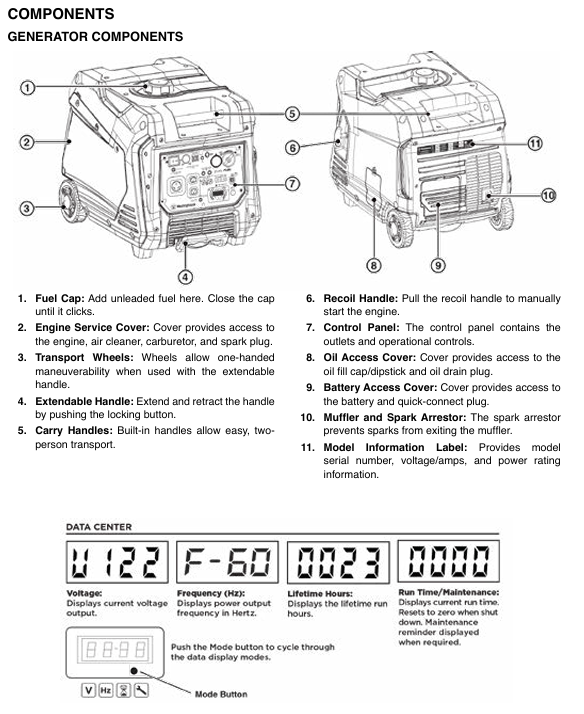
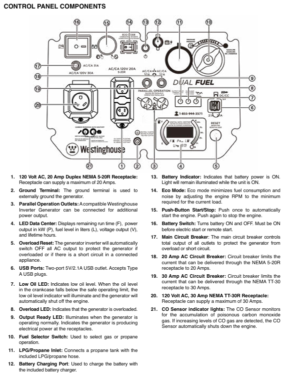
Easy to operate: triple guarantee of remote start, electric start, and manual start, clear layout of control panel, LED data center displaying key information such as remaining operating time, power output, fuel level, etc.
Core functions and operation guide
1. Core functional features
(1) Dual fuel switching system
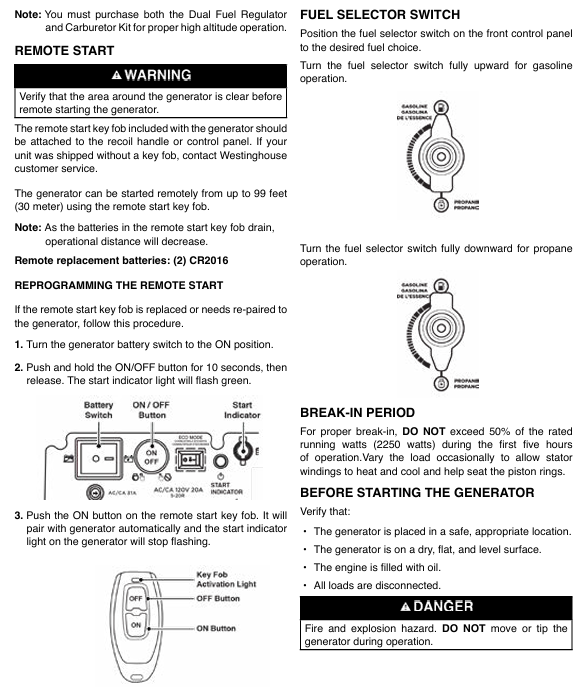
Switching logic: The control panel is equipped with a fuel selection switch (up gasoline, down propane), which supports switching during operation (propane cylinder needs to be connected in advance). During switching, the engine may briefly shake (draining residual fuel from the carburetor), which is a normal phenomenon.
Propane adaptation: Supports any standard propane cylinder (20 pounds, 30 pounds, etc.) with overcharge protection device (OPD), with sufficient hose length to keep the cylinder away from the generator (to avoid heat sources), and a leak free interface design (can be manually tightened without the need for a raw material belt).
Fuel consumption: In gasoline mode with light load (50% power), the fuel consumption is about 0.6 gallons per hour, and the full tank range is 18 hours; The fuel consumption in propane mode is about 0.5 pounds per hour, and the range of a 20 pound cylinder is about 40 hours.
(2) Detailed explanation of starting the system
Precautions for startup mode operation steps
Remote start 1. Turn on the generator battery switch
2. Press the "ON" button on the remote control (green)
3. After starting the engine, wait for 30 seconds for stable output. The remote control distance is up to 30 meters, and the battery model is 2-cell CR2016. The distance is shortened when the battery is low; Operate within the line of sight of the generator
Electric start 1. Confirm that the battery switch is turned on
2. Press the "START/STOP" start button on the control panel
3. If the battery fails to start after a 30 second interval and the battery voltage is insufficient, it needs to be charged with a matching charger for 8 hours (do not exceed 8 hours to avoid overcharging)
Hand pulled start 1. Slowly pull the rope until there is resistance (compression stroke)
2. Quickly pull the rope and release it after starting, suitable for low battery life or low-temperature environments; Do not forcefully pull or tug to avoid rope breakage
(3) ECO mode and power management
ECO mode enabled: After the output ready indicator light (green) lights up, press the "ECO" switch, and the indicator light will turn on to indicate activation; At this time, the engine speed changes with the load (the lower the load, the lower the speed), reducing fuel consumption by 30% and noise by 10-15 decibels.
Applicable scenarios: Suitable for low-power continuous loads (such as lighting fixtures, computers, and mobile phone charging); It is recommended to turn off ECO mode for high-power devices such as 1.5 horsepower air conditioners and 1/3 horsepower water pumps to avoid insufficient power during startup.
Load management principles:
All loads must be disconnected during startup to avoid overload triggering protection.
Connect the load sequentially: first connect high-power devices (such as refrigerators and air conditioners), and then connect low-power devices after stable operation.
Total operating power ≤ rated power (gasoline 3700W/propane 3330W), avoid approaching peak power for a long time (only for short-term use during startup).
(4) Security protection system
CO sensor protection: Real time monitoring of surrounding carbon monoxide concentration. When the concentration exceeds the standard (or other fuel combustion exhaust is detected), the engine will automatically shut down, and the red CO indicator light on the control panel will flash and give an alarm; Move to a ventilated area, power off for 30 seconds, and then restart.
Low oil protection: When the oil level is below the safety mark (L), the low oil indicator light (yellow) lights up and the engine automatically shuts down; Add engine oil between L-H and press the reset button to restart.
Overload/Short Circuit Protection: When the load exceeds the rated power or is short circuited, the corresponding circuit breaker trips and the overload indicator light (red) lights up; The overloaded equipment needs to be disconnected, the circuit breaker reset pressed, and the equipment checked for any faults before reconnecting.
High temperature protection: When the engine temperature exceeds the safe value, it will automatically reduce power or shut down to avoid damage; Check if the heat dissipation port is blocked, move to a cool place to cool down, and restart.
2. Complete operation process (taking gasoline mode as an example)
(1) First use preparation
Oil filling:
The new machine has no oil. Open the oil compartment cover (side), take out the dipstick, and use the matching funnel to add 10W-30 engine oil. Add a small amount each time and check the dipstick multiple times to ensure that the liquid level is between L (low) and H (high). Overfilling is prohibited.
Tighten the dipstick and oil compartment cover, wipe off any spilled oil (to avoid high temperature ignition).
Fuel injection:
Open the fuel tank cap (top), add 87-93 octane gasoline (ethanol content ≤ 10%), observe the red filling ring in the fuel tank, and fill it below the filling ring (reserve expansion space). Overfilling is prohibited.
Tighten the fuel tank cap, wipe off any spilled gasoline, and wait for 5 minutes for the fuel to flow into the carburetor.
Battery connection:
Open the battery compartment cover (side), remove the battery, connect the quick connector (red to red, black to black), fix the battery with rubber tape, and cover the compartment cover.
(2) Start operation
Check the placement of the generator: Ensure it is located outdoors in a well ventilated area, with a flat and dry ground, no flammable materials around, and leave 1.5 meters of ventilation space.
Open the fuel tank valve: Rotate the fuel tank valve clockwise to the "ON" position (perpendicular to the pipeline).
Fuel selection: Turn the fuel switch on the control panel to the "GAS" (gasoline) position.
Start the engine: Select remote control, electric start, or manual start. After starting, the engine will idle for 30 seconds, and the output ready indicator light (green) will light up to connect the load.
(3) Operation and load connection
Connection sequence: First connect high-power devices (such as refrigerators, with a starting power of about 2200W), and then connect low-power devices (such as lighting fixtures and USB charging) after stable operation.
Power monitoring: Real time power output can be viewed through the LED data center to avoid exceeding the rated power (3700W gasoline).
Fuel switching (if required):
Connect the propane cylinder in advance and open the valve. Press the fuel selection switch to the "PROPANE" position and close the fuel tank valve.
After switching, the engine may briefly become unstable, but it will return to normal after about 1 minute. If it is stopped, the load needs to be disconnected and restarted.
(4) Shutdown operation
Disconnect all loads: unplug all electrical plugs and let the generator run without load for 3-5 minutes (to cool the engine).
Stop the engine: Press the "START/STOP" stop button on the control panel (or the "OFF" button on the remote control) to shut down the engine.
Close the fuel valve: Close the fuel tank valve in gasoline mode, and close the cylinder valve in propane mode (tighten clockwise).
Long term shutdown: Turn off the battery switch, cover with a dust cover (plastic cover is prohibited to avoid moisture), and place in a dry and ventilated place.
Installation and usage specifications
1. Installation and placement requirements
Placement environment:
Can only be used outdoors, at least 1.5 meters (5 feet) away from doors, windows, ventilation openings, and air conditioning units. It is prohibited to use indoors, in garages, basements, tents, and other enclosed/semi enclosed spaces to prevent carbon monoxide poisoning.
Place on a hard and flat surface (cement floor, wooden board) to avoid sand, grass debris, and soil blocking the heat dissipation outlet; Do not operate on slopes to prevent uneven oil lubrication or fuel leakage.
Grounding requirements:
When only using a socket for direct power supply, there is no need for additional grounding (generator neutral line floating design).
If connecting to the building power supply system (such as a household distribution box), a professional electrician must install a transfer switch (in accordance with NFPA 70 standard) and connect the generator grounding terminal to the grounding electrode (grounding resistance ≤ 4 Ω).
Protection requirements: Do not use in rainy, snowy, or humid environments to avoid rainwater splashing onto control panels or sockets; If temporary outdoor use is required, a rain shelter should be built (to ensure ventilation) and it is prohibited to cover the generator.
2. Extension cable and load adaptation
(1) Extension cable selection
Load current extension cable length ≤ 15 meters Extension cable length ≤ 30 meters Precautions
≤ 10A (such as lamps, computers) 16AWG 3-core grounding extension wire 14AWG 3-core grounding extension wire must use outdoor dedicated, undamaged, and well grounded extension wire
10-20A (such as microwave ovens and small air conditioners) 14AWG 3-core grounding extension cable 12AWG 3-core grounding extension cable. The shorter the length of the extension cable, the better to reduce voltage drop
20-30A (such as RV RVs, high-power water pumps) 12AWG 3-core grounding extension wire 10AWG 3-core grounding extension wire is prohibited from using multi joint extension wires to avoid overload and heating
(2) Common Load Adaptation Table
Equipment type Operating power (W) Starting power (W) Adaptation fuel mode Remarks
Laptop 60-100 60-100 gasoline/propane can activate ECO mode for the longest range
55 inch LED TV 80-150 80-150 gasoline/propane can be connected to the light fixture simultaneously
Household refrigerator (double door) 700-1000 2000-2500 gasoline with high starting power, needs to be started separately before connecting other devices
1.5 horsepower air conditioner (window type) 1200-1500 3000-3500 gasoline with ECO mode off to ensure sufficient peak power
RV RV (regular load) 1500-2500 3000-4000 gasoline/propane use 30A dedicated socket to avoid starting multiple high-power devices at the same time
1/3 horsepower water pump 800-1000 2000-2500 may trigger overload protection when starting gasoline, and other loads need to be disconnected
3. Parallel operation (parallel wires need to be purchased separately)
Applicable scenario: When a single generator has insufficient power (such as supplying power to 2 air conditioners), it can be connected in parallel with another compatible Westinghouse variable frequency generator (such as iGen4500DFc, iGen4000).
Operation steps:
Turn off two generators, disconnect all loads, and ensure that the battery switch is turned off.
Connect parallel wires: Connect the black wire to the black parallel interface of two generators, connect the red wire to the red interface, and connect the green grounding wire to the grounding terminal.
Start two generators in sequence and wait for their respective output ready indicator lights to turn on (green).
Connect the load to the socket of one of the generators, and the load will be shared between the two generators, with a total rated power ≤ the sum of the rated powers of the two generators.
Attention: Do not enable ECO mode when parallel connection is made; The fuel mode of the two generators must be consistent (both gasoline or propane); The total rated power of the load is ≤ 80% of the total rated power to avoid overload.
Maintenance and upkeep
1. Regular maintenance schedule
Maintenance project maintenance cycle operation content
Oil check: Before each use or after every 8 hours of operation, take out the dipstick, wipe it clean, insert and tighten it, take it out and check the liquid level. If it is below the L mark, add 10W-30 oil
The first 25 hours or 1 month of oil change; After heating up every 50 hours or 6 months, drain the oil (with the drain bolt at the bottom), replace the new engine oil (0.6L), and replace the drain bolt copper washer (Part # 94007)
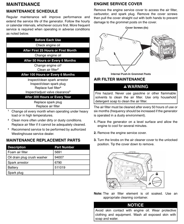
Clean the air filter every 50 hours or 6 months; In dusty environment, shorten it to 25 hours, take out the foam filter element, clean it with detergent, soak a small amount of engine oil after drying (squeeze out the excess), and reinstall; Replace if damaged (Part # 5691)
Spark plug maintenance check every 100 hours; Replace spark plugs every 300 hours or 1 year (using matching sockets), clean carbon deposits, check clearances (0.60-0.80mm), and replace damaged ones (recommended model F7RTC)
Clean the Mars extinguisher every 100 hours or 6 months, remove the muffler cover, clean the carbon deposits on the filter screen, and replace if damaged (Part # 6790); Excessive carbon deposition can lead to a decrease in power
When the battery is not used for a long time during maintenance, it should be charged for 8 hours per month using the matching charger to avoid damage caused by power loss; The battery life is about 2-3 years, replace it after damage (Part # 511019)
Fuel system maintenance: Clean the fuel tank filter every 6 months and check the fuel pipeline for any damage or leakage; Long term storage requires the addition of fuel stabilizers
2. Storage specifications
(1) Short term storage (within 1 month)
Close the fuel valve and let the engine run to automatic stop (drain carburetor fuel).
Turn off the battery switch, wipe off the dust and oil stains on the surface of the generator, place it in a dry and ventilated place, and cover it with a dust cover (breathable material).
Start the generator and run it for 10 minutes per month (with light load) to maintain engine lubrication.
(2) Long term storage (over 6 months)
Drain fuel:
Gasoline mode: Open the fuel tank drain bolt, empty the fuel tank (store it in an approved container), start the engine until it stops (empty the carburetor).
Propane mode: Close the cylinder valve, start the engine until it stops (empty the fuel pipeline).
Engine maintenance:
Replace the engine oil, remove the spark plug, inject 1 teaspoon of engine oil into the cylinder, pull the pull rope several times (to evenly distribute the engine oil), and reinstall the spark plug.
Battery handling: Disconnect the battery connector, store it separately after being fully charged, and charge it once a month.
Storage environment: Dry, ventilated, cool, away from sources of fire and heat, prohibited from mixing with flammable materials.
3. Common troubleshooting
Possible causes and solutions for fault phenomena
Unable to start 1. No oil or low oil level
2. Fuel not turned on or fuel depleted
3. Spark plugs that are damp, have carbon deposits, or have improper gaps
4. Insufficient battery voltage (electric start) 1. Add engine oil to the standard level
2. Open the fuel valve or add fuel
3. Remove the spark plug to dry/clean the carbon deposits, adjust the gap to 0.6-0.8mm, and replace if damaged
4. Charge for 8 hours with the matching charger
Stop immediately after startup. 1. CO sensor alarm (concentration exceeding standard)
2. Low oil protection triggered
3. Overload protection not reset
4. Fuel pipeline blockage 1. Move to a ventilated area, cut off power for 30 seconds, and restart
2. Add engine oil
3. Disconnect the load and press the overload reset button
4. Check the fuel pipeline and clean the filter screen
No output power 1. The output ready indicator light is not on
2. Circuit breaker tripping
3. Socket malfunction or damaged extension cord
4. Frequency conversion module failure: 1. Wait for the engine to run for 30 seconds, and then connect the load after the output stabilizes
2. Check the load and reset the circuit breaker
3. Replace the intact extension cord and check the socket wiring
4. Contact customer service for repair
Unstable operation/power decrease 1. Excessive or expired fuel impurities
2. Air filter blockage
3. Mars Extinguisher Carbon Accumulation
4. Insufficient propane pressure (propane mode) 1. Replace with fresh fuel
2. Clean or replace the air filter
3. Clean the filter screen of the Mars extinguisher
4. Replace the full bottle of propane and check that the hose is not bent
Excessive noise/severe vibration 1. ECO mode not activated (light load)
2. Uneven placement or damaged rubber foot pads
3. Excessive carbon buildup in the engine
4. Loose fan or other components 1. Activate ECO mode under light load
2. Move to a flat surface and replace the damaged foot pad
3. Clean the engine carbon deposits and replace the engine oil
4. Check and tighten loose parts
Propane mode cannot start. 1. Gas cylinder valve not open
2. Leakage at the hose interface
3. The residual gasoline in the carburetor has not been emptied
4. Low propane pressure (low temperature environment) 1. Fully open the cylinder valve
2. Check the interface with soapy water and tighten it again
3. Switch to gasoline mode and run for 5 minutes, then switch back to propane
4. Move the gas cylinder to a warm environment and start it after the pressure is restored
Safety precautions and warranty
Risk of carbon monoxide poisoning:
Only for use in outdoor ventilation areas, carbon monoxide detectors (with battery backup) need to be installed at home.
If symptoms such as dizziness, nausea, and fatigue occur, immediately move to fresh air and call the emergency number. It may be carbon monoxide poisoning.
Fire and explosion risks:
Smoking and staying away from open flames are prohibited when refueling, and contact with mufflers is prohibited when heating up (temperatures can reach 200 ° C or above).
Propane cylinders should be placed upright on the ground, away from generator mufflers and direct sunlight. It is prohibited to invert or impact the cylinder.
After fuel spillage, wipe it clean and wait for 5 minutes for the fuel to evaporate before starting. Do not ignite the spilled fuel.
Electric shock risk:
Do not use in damp environments or rainy days, and do not touch sockets and control panels when your hands are wet.
When connecting/disconnecting loads, the device power should be turned off to avoid arcing caused by live plugging and unplugging.
Operational safety:
Children and pets should stay away from running generators and are prohibited from playing near them.
During maintenance, it is necessary to disconnect the power and fuel, and wait for the engine to completely cool down (at least 30 minutes) before operating.
- OMRON
- ABB
- General Electric
- EMERSON
- Honeywell
- HIMA
- ALSTOM
- Rolls-Royce
- MOTOROLA
- Rockwell
- Siemens
- Woodward
- YOKOGAWA
- FOXBORO
- KOLLMORGEN
- MOOG
- KB
- YAMAHA
- BENDER
- TEKTRONIX
- Westinghouse
- AMAT
- AB
- XYCOM
- Yaskawa
- B&R
- Schneider
- KONGSBERG
- NI
- WATLOW
- ProSoft
- SEW
- ADVANCED
- Reliance
- TRICONEX
- METSO
- MAN
- Advantest
- STUDER
- DANAHER MOTION
- Bently
- Galil
- EATON
- MOLEX
- DEIF
- B&W
- ZYGO
- Aerotech
- DANFOSS
- Beijer
- Moxa
- Rexroth
- Johnson
- WAGO
- TOSHIBA
- BMCM
- SMC
- HITACHI
- HIRSCHMANN
- Application field
- XP POWER
- CTI
- TRICON
- STOBER
- Thinklogical
- Horner Automation
- Meggitt
- Fanuc
- Baldor
- SHINKAWA
- Other Brands
- UniOP
- KUKA
- Iba
- Beckhoff
-
 Basler D90 96801 100 PCB Card
 -
 Basler XR2002F Voltage Regulator (110 VAC, 48-480 Hz)
 -
 Basler SR8A-2B14B3A Regulator
 -
 Basler 9561500100 Module
 -
 Basler DECS-400 BE1-11 System
 -
 Basler DECS-100-B15 Excitation Control
 -
 Basler SCP 210 Frequency Controller
 -
 Basler SR4A-2B15B3A Static Voltage Regulator
 -
 Basler BE1-32R Power Relay
 -
 Basler PIA2400-17GM Power Interface Adapter
 -
 Basler MVC 232 Manual Voltage Control Module
 -
 Basler SSR 32-12 Static Voltage Regulator
 -
 Basler 5MW AVR Generator Voltage Regulator
 -
 Basler VR63-4B Voltage Regulator
 -
 Basler DECS-100-A05 AVR for Engine Generator
 -
 Basler DECS-100-B15 Automatic Voltage Regulator
 -
 Basler BE1-32R Directional Power Relay
 -
 Basler BE1-87B Differential Relay
 -
 Basler UFOV 260A Protective Module
 -
 Basler 9-2614-02-100 PCB Rev M
 -
Basler DECS-100-B15 Digital AVR
-
 Basler 9284900103 PS DECS-400N
 -
 Basler D4N3H1U Intertie Protection
 -
 Basler DECS-100-B15 A15 AVR
 -
 Basler KR4F Voltage Regulator
 -
 Basler BE26434 T14 Transformer
 -
 Basler SR8A-2B15B3A Regulator
 -
 Westinghouse 774B472A12 AR Relay
 -
Basler DECS-100-B15 AVR
-
Basler XR2002F Regulator 110V
-
Basler SR125-E Static Regulator
-
 Basler SSR 125-12 Regulator
 -
 Basler MOC2599 Motor Pot
 -
 Basler BE1-DFPR Feeder Relay
 -
 Basler CBS 305 Current Boost
 -
 Basler BE1-25 AutoSync
 -
 Basler MVC 300 Voltage Control
 -
 Basler BE3-25A AutoSync
 -
 Basler KR7FF Static Regulator
 -
 Basler 90-49000-100 Regulator
 -
 Basler 880 kVA Dry Type Transformer Specs
 -
 Basler Electric BE1-25 Sync-Check Relay Specs
 -
 Basler SSR 125-12 Voltage Regulator Specs
 -
 Basler Electric BE1-851 Overcurrent Relay Review
 -
Basler Electric 149D930G02 Control Sub-Assembly
-
 Basler Electric BE1-81O/UT Frequency Relay Specs
 -
 Basler Electric BE1-51/27C Overcurrent Relay
 -
 Basler Electric 149D956G02 Industrial Component
 -
Basler Electric BE1-51A Overcurrent Relay Specs
-
 Basler Electric BE1-40Q Loss of Excitation Relay
 -
 Basler DECS-200 Excitation Control System
 -
 Basler DECS-200 Voltage Regulator 56-277V AC / 125V DC
 -
Basler BE1-87T Transformer Differential Relay
-
 Basler RDP-110-S1 Protection Relay
 -
 Basler BE1-700V Digital Protective Relay
 -
 Basler BE1-951 Overcurrent Protection System
 -
 Basler DECS-300 Digital Excitation Control
 -
 Basler DECS-200 Digital Excitation Control
 -
 Basler DECS-200-1C Excitation Control System
 -
Basler DECS-200-1L Digital Excitation Control
-
 Basler Electric BE1-GPS Generator Protection System
 -
Basler Electric DECS-200-1C Digital Excitation Controller
-
 Basler Electric DECS125-15 Excitation Control with Power Module
 -
 Basler Electric BE1-87G Differential Relay
 -
 Basler Electric BE1-11 Protection System I5A3M2P2N0EA00
 -
Basler Electric DECS-200-1C Excitation Control System
-
Basler Electric BE1-11g Generator Protection Relay
-
Basler Electric DECS 125-15-B2C1 V2.0.9 Excitation Control
-
 Basler Electric BE1-81O/UT3ED1JA7N2F Frequency Relay
 -
Basler Electric BE1-81O/UT3EE1YB7N1F Frequency Relay
-
 Basler Electric DECS-200-1L Digital Excitation Control System
 -
Basler DECS125-15-B2C1 Excitation Control
-
 Basler 9507900205 SSR Retrofit Voltage Regulator
 -
 Basler BE2000E Digital Voltage Regulator
 -
 Basler BE1-GPS Generator Protection System
 -
Basler DECS-250-CN1CN1N Digital Excitation Control
-
 Basler DGC-2020 Genset Controller
 -
 Basler BE1-81O UT3ED1LA7N0F Frequency Relay (Variant)
 -
 Basler BE1-81O UT3EE1YA9S0F Frequency Relay (Variant)
 -
Basler BE1-81O Over/Under Frequency Relay
-
Basler DECS125-15 Digital Excitation Control
-
Basler Electric BE1-951 Overcurrent Protection System
-
 Basler Electric BE1-700V Digital Protective Relay
 -
 Basler Electric APR63-5 Automatic Voltage Regulator
 -
Basler Electric BE1-851 Overcurrent Protection System
-
Basler Electric DECS-250-LN1SN1N Excitation Control
-
 Basler Electric BE1-87T Transformer Differential Relay
 -
Basler Electric DECS-200-1L Excitation Control System
-
 Basler Electric 9310300100 DECS-300 Excitation Control
 -
 Basler Electric SSE-N 125-4.5KW Shunt Exciter Regulator
 -
 Basler Electric DGC-2020HD-5NS1DNSBA Genset Controller
 -
Basler Electric BE1-81-O/UT3EE1JB7N1F Frequency Relay
-
Basler Electric BE1-81T1EE1WA0N1F Frequency Relay
-
 Basler Electric BE1-25M1EA6PN5R1F Sync-Check Relay
 -
 Basler Electric BE1-GPS Generator Protection System
 -
Basler Electric DECS-250-LN1SN1N Excitation Control Rev V
-
 Basler Electric DECS-250-CN2CN1N Excitation Control
 -
Basler Electric BE1-50/51B-207 Overcurrent Relay
-
Basler Electric DECS-300-C0N0 Excitation Control System
-
Basler Electric DECS-200 Digital Excitation Control System
-
Basler Electric DECS-250-LN1CN1N Excitation Unit
-
Basler Electric DECS-250 LN2SA1D Excitation Unit Specs
-
Basler Electric BE1-87T Transformer Relay Review
-
Basler Electric BE1-11 Protection System
-
Basler Electric BE1-GPS100-E4N1H1N Protection System
-
 Allen-Bradley 442G-MABH-R Safety Module
 -
 Beckhoff CX1030-0111 PLC Assembly Profile
 -
 FANUC IC693CPU364 PLC Module
 -
 Orange Denmark Type 200816 220 PLC Specs
 -
 OMRON C200H-SNT31 Sysmac PLC Module
 -
 Allen Bradley 20AB022A3AYNANC0 PowerFlex 70
 -
 OMRON C200HW-PCU01 Position Control Unit
 -
 ABB AO845A-eA Analog Output Module
 -
 OMRON CJ1M-CPU22 CPU Unit
 -
 Allen Bradley 100-E265ED11 Contactor
 -
 Honeywell 51304511-100 Interface Module
 -
 SOLEXY BXF3S0101N0018 Gateway Module
 -
 OMRON CJ2H-CPU65 CPU Unit
 -
 Automation Direct GS2-45P0 AC Drive
 -
 M68-2000 2-Axis Motion CNC Controller
 -
 OMRON CJ1M-CPU11 V3.0 PLC CPU Unit
 -
 OMRON CJ1W-NC413 4-Axis Positioning Controller
 -
 OMRON 3G2A3-PRO16 Programming Console HMI
 -
 Siemens 3VT8440-2AA04-2GA2 Molded Case Circuit Breaker
 -
 Siemens 3RT5045 Contactor Series
 -
 OMRON C200HS-CPU01-E SYSMAC PLC Controller
 -
 OMRON C500-NC103-E Positioning Control Unit
 -
 OMRON CJ1W-TC001 Temperature Control Unit


