
Watlow plug-in heater
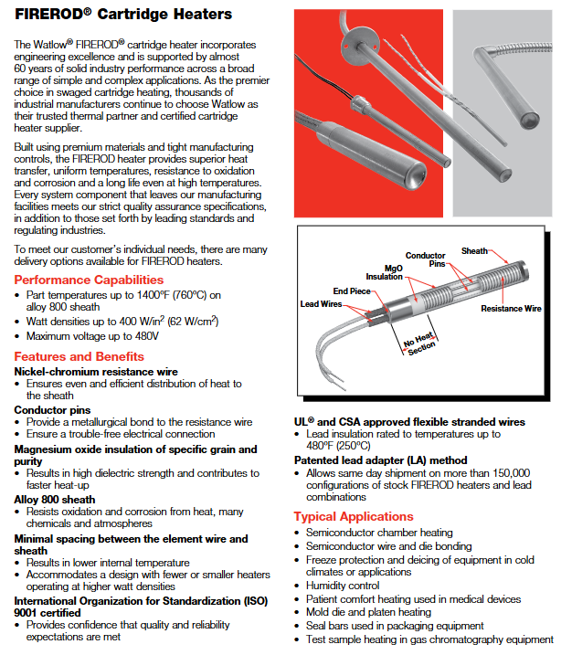
FIREROD ® Universal plug-in heater 1400 ° F (760 ° C) (Alloy 800 sheath) 400 W/in ² (62 W/cm ²) 60 years of industry validation, high thermal conductivity efficiency, supports multi scenario customization
High temperature FIREROD high-temperature working condition specific 1800 ° F (982 ° C) 100 W/in ² (15.5 W/cm ²) sealing design reduces oxidation, high emissivity sheath enhances heat transfer
Metric FIREROD global adaptation 1400 ° F (760 ° C) 330 W/in ² (50 W/cm ²) meets metric standards, has high dimensional accuracy, and is compatible with international equipment
MULTICELL ™ Multi zone precise temperature control 2050 ° F (1120 ° C) 30 W/in ² (4.6 W/cm ²) up to 6 independent temperature control zones, loose assembly design for easy disassembly and assembly
Watlow plug-in heater
Product Family and Core Features
1. Product Line Overview
Core positioning of product series: Maximum operating temperature, maximum power density, key advantages
FIREROD ® Universal plug-in heater 1400 ° F (760 ° C) (Alloy 800 sheath) 400 W/in ² (62 W/cm ²) 60 years of industry validation, high thermal conductivity efficiency, supports multi scenario customization
High temperature FIREROD high-temperature working condition specific 1800 ° F (982 ° C) 100 W/in ² (15.5 W/cm ²) sealing design reduces oxidation, high emissivity sheath enhances heat transfer
Metric FIREROD global adaptation 1400 ° F (760 ° C) 330 W/in ² (50 W/cm ²) meets metric standards, has high dimensional accuracy, and is compatible with international equipment
MULTICELL ™ Multi zone precise temperature control 2050 ° F (1120 ° C) 30 W/in ² (4.6 W/cm ²) up to 6 independent temperature control zones, loose assembly design for easy disassembly and assembly
2. Core common advantages
Material and Structure: Made of nickel chromium resistance wire (uniform heating), magnesium oxide (MgO) insulation layer with specific grain purity (high dielectric strength, rapid heating), Alloy 800 or stainless steel sheath (anti-oxidation, corrosion-resistant).
Process design: Minimize the distance between the resistance wire and the sheath, reduce internal temperature, and support high power density operation; UL ®/ CSA certified leads, with insulation levels ranging from 250 ° C to 842 ° C.
Safety and reliability: non-volatile design, strong high-temperature stability; Some models support low leakage construction and are suitable for sensitive scenarios such as healthcare.

Detailed explanation of key technical specifications
1. Dimensions and tolerances
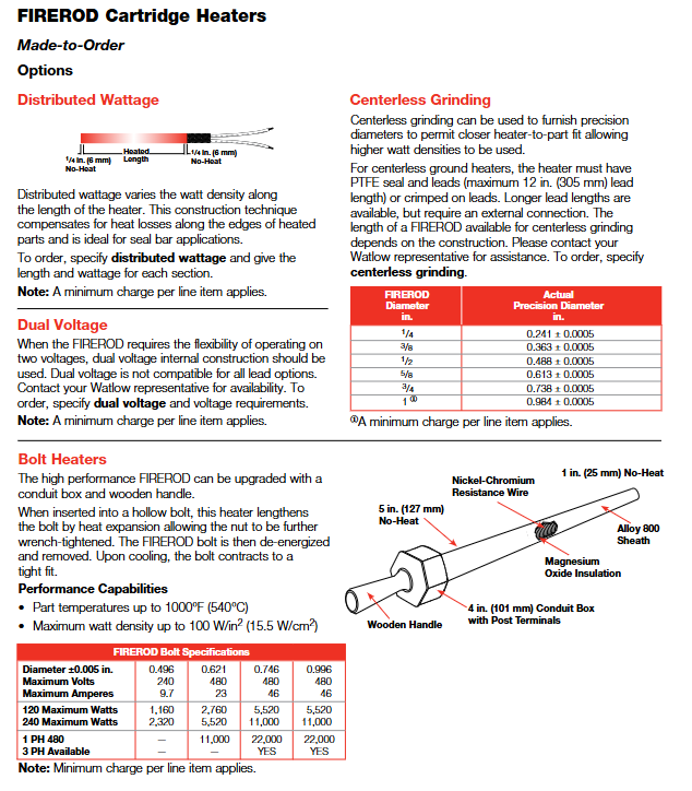
(1)FIREROD ® standard size
Nominal diameter (in) Actual diameter (in/mm) Minimum sheath length (in/mm) Maximum sheath length (in/mm) Diameter tolerance
1/8 0.122(3.1) 7/8(22.2) 12(305) ±0.002 in(±0.05 mm)
1/4 0.246(6.3) 7/8(22.2) 36(915) ±0.002 in(±0.05 mm)
1/2 0.496(12.6) 7/8(22.2) 60(1520) ±0.002 in(±0.05 mm)
1 0.996(25.3) 1 1/4(32.0) 72(1830) ±0.003 in(±0.08 mm)
(2) Tolerance requirements
Length tolerance: The sheath with a length tolerance of ≤ 4.5 in (114 mm) is ± 3/32 in (± 2.4 mm); The sheath with a diameter greater than 4.5 inches is ± 2% (1/8 inch diameter is ± 3%).
Power tolerance: 1/8 inch diameter is+10%/-15%, other diameters are+5%/-10%.
Resistance tolerance: 1/8 inch diameter is+15%/-10%, other diameters are+10%/-5%; Resistance varies with temperature, with room temperature (before use) being 90% of the value calculated by Ohm's Law, and after use being 95%.
2. Electrical performance
(1)FIREROD ® Voltage and power range
Diameter (in) Maximum voltage (V) Maximum current (A) 120V Minimum power (W) 240V Maximum power (W)
1/8 240 3.1 - 720
1/4 240 4.4 100 1050
3/4 480 23.0 30 5520
1 480 23.0 - 5520
(2) Metric FIREROD Electrical Parameters (Example)
Diameter (mm) Maximum voltage (V) 230V Maximum power (W) 400V Maximum power (W) Maximum current (A)
6.5 250 1650 - 7.2
16 480 4830 8400 21
20 480 4830 8400 21
3. Power density and application adaptation
Power density directly affects heating efficiency and heater lifespan, and should be selected based on the heating medium and operating conditions
Metal heating: The maximum allowable power density varies with the aperture fit gap and temperature (for example, at 1400 ° F, a fit gap of 0.005 in corresponds to a power density of approximately 80 W/in ²).
Air/gas heating: At an ambient temperature of 70 ° F, the maximum allowable power density for a single heater is approximately 60 W/in ²; When multiple devices are parallel, they need to be multiplied by a correction factor of 0.95, and when equipped with a reflector, they need to be multiplied by 0.85.
Mobile air heating: The higher the wind speed, the greater the allowed power density (for example, at a wind speed of 100 FPM, the power density can reach 1000 W/in ²).
Installation and Wiring Guide
1. Installation preparation
Aperture matching: It is recommended that the aperture be 0.001-0.006 inches larger than the actual diameter of the heater (for metal heating). A gap that is too large can reduce thermal efficiency, while a gap that is too small may make disassembly difficult.
Installation location: The sensor should be installed in a temperature uniform area, away from the edge of the heat source; The sheath should be in full contact with the heating medium to avoid local overheating.
Environmental requirements: Avoid installing in close proximity to noise sources such as motors and relays; In humid environments, models with sealing (PTFE/silicone) should be selected.
2. Wiring specifications
(1) Lead type and specifications
Lead type, maximum temperature, applicable scenarios, wire diameter specifications (example)
GGS fiberglass 482 ° F (250 ° C) universal scenario 18 AWG (1/2 inch diameter heater)
MGT 842 ° F (450 ° C) high temperature scenario 18 AWG (3/4 inch diameter heater)
PTFE 392 ° F (200 ° C) corrosion-resistant scenario 20 AWG (3/8 in diameter heater)
Mineral Insulation (MI) 1500 ° F (815 ° C) Extreme High Temperature/Vibration Scenarios Conductor Diameter 0.044 in (3/8 in diameter heater)
(2) Wiring precautions
Lead length: Standard length of 12 inches (305 mm), customizable extension, extra long leads need to consider voltage drop (recommended wire diameter not less than 22 AWG).
Grounding requirements: Models with grounding leads must be reliably grounded to avoid the risk of electrical leakage; In high temperature scenarios, the lead wire should be kept away from the sheath (with a minimum length of 1 inch without thermal zone).
Multi zone control: MULTICELL ™ The heater needs to be wired separately for each temperature control zone to ensure independent adjustment.
3. Fixed method
Flange fixing: Stainless steel flange (FS/FM/FL type), suitable for panel installation, flange position can be customized (standard distance from lead end 1/4 in).
Threaded fixation: 304 stainless steel or brass threaded joints (NPT/DIN specifications), waterproof installation, suitable for pipeline or threaded hole scenarios.
Positioning ring: Stainless steel positioning ring, used for non precision fixed scenarios, installed at the end of the no heat zone.
Customized Options and Selection Guide
1. Core customization options
(1) End and sealing options
Option Type Function Applicable Temperature Minimum No Hot Zone Length
PTFE seal and lead anti moisture, oil, solvent 392 ° F (200 ° C) 1 in (25 mm)
Silicone sealing and lead anti moisture, mild corrosion 302 ° F (150 ° C) 1 in (25 mm)
Epoxy resin sealing high temperature sealing (up to 260 ° C) 260 ° F (500 ° C) 1 in (25 mm)
Mineral Insulated (MI) Seal for Extreme High Temperature, Vibration, Corrosion 1500 ° F (815 ° C) 6 in (152 mm)
(2) Lead protection options
Stainless steel hose: wear-resistant, suitable for harsh environments, standard length of 12 inches, lead wire 2 inches longer than hose.
Stainless steel woven mesh: high flexibility, wear-resistant, standard length of 12 inches, supports right angle wire output.
Galvanized conduit: Abrasion protection, with 90 ° bend, standard length 8 inches.
(3) Function extension options
Built in thermocouples: Style A (monitoring the internal temperature of the heater), Style B (approximate workpiece temperature), Style C (end temperature, suitable for plastic molding), supporting J/K type.
Distributed power: Set different power densities in segments along the length of the heater to compensate for edge heat loss (suitable for scenarios such as sealing strips).
Dual voltage design: supports switching between two voltages and is suitable for multi scenario power supply (only available for metric models with diameters of 12.5 mm and above).
Extension without hot zone: The lead end or terminal without hot zone can be extended (up to 2.5 inches) to avoid the influence of high temperature on the lead.
2. Selection steps
Determine operating parameters: maximum working temperature, heating medium (metal/air/liquid), aperture and installation method.
Calculate power demand: Determine the required power based on the heating area, heating rate, and heat loss (recommended power density not exceeding the maximum allowable value of the corresponding medium).
Select product series: FIREROD for general scenarios ®, Choose high-temperature FIREROD for high temperature scenarios, metric models for international equipment, and MULTICELL for multi zone temperature control ™。
Customized function options: Select the sealing type according to the environment, choose the lead protection and fixing method according to the installation space, and select the built-in thermocouple according to the temperature control accuracy.
Maintenance and troubleshooting
1. Daily maintenance
Regular inspection: Check the insulation layer of the lead wires and the sheath for oxidation and discoloration every month, and replace them promptly if any problems are found.
Cleaning and maintenance: Remove dust and oil stains from the surface of the sheath to avoid affecting heat transfer; WATLUBE can be used for disassembly ™ Lubricant, easy to disassemble and does not affect thermal conductivity.
Life management: Under high temperature conditions (such as above 1400 ° F), it is recommended to regularly check the resistance value and replace the heater when the resistance changes by more than 10%.
2. Common faults and solutions
Possible causes and solutions for the fault phenomenon
Slow heating, insufficient power density, loose aperture fit, excessive lead voltage drop, replacement with higher power model, adjustment of aperture gap, and thickening of lead wire diameter
Improper installation position due to local overheating, poor medium contact, adjust installation position, and ensure that the protective cover is fully attached to the heating surface
Damaged leads, high temperature baking, wear, corrosion, extended no heat zone, replacement of protected lead options (hose/braided mesh), selection of corrosion-resistant seals
Excessive leakage, insulation layer affected by moisture or damage, replacement of sealing model, drying environment, and inspection of reliable grounding
High power density due to heater burnout, reduced power density due to dry burning of medium, ensuring sufficient heating medium, and installing temperature protection devices
Typical application scenarios
Semiconductor manufacturing: wafer bonding, chamber heating (using high cleanliness, low leakage FIREROD) ®, With PTFE seal).
Plastic molding: mold heating, sealing strip heating (using models with distributed power and built-in thermocouples).
Medical equipment: patient insulation, instrument heating (using low leakage, small-sized FIREROD) ®)。
Freezing protection: Anti icing of equipment in low-temperature environments (using high-power density, waterproof sealing models).
High temperature process: Superplastic forming of titanium alloy, diffusion welding (using high-temperature FIREROD or MULTICELL) ™)。
- OMRON
- ABB
- General Electric
- EMERSON
- Honeywell
- HIMA
- ALSTOM
- Rolls-Royce
- MOTOROLA
- Rockwell
- Siemens
- Woodward
- YOKOGAWA
- FOXBORO
- KOLLMORGEN
- MOOG
- KB
- YAMAHA
- BENDER
- TEKTRONIX
- Westinghouse
- AMAT
- AB
- XYCOM
- Yaskawa
- B&R
- Schneider
- KONGSBERG
- NI
- WATLOW
- ProSoft
- SEW
- ADVANCED
- Reliance
- TRICONEX
- METSO
- MAN
- Advantest
- STUDER
- DANAHER MOTION
- Bently
- Galil
- EATON
- MOLEX
- DEIF
- B&W
- ZYGO
- Aerotech
- DANFOSS
- Beijer
- Moxa
- Rexroth
- Johnson
- WAGO
- TOSHIBA
- BMCM
- SMC
- HITACHI
- HIRSCHMANN
- Application field
- XP POWER
- CTI
- TRICON
- STOBER
- Thinklogical
- Horner Automation
- Meggitt
- Fanuc
- Baldor
- SHINKAWA
- Other Brands
- UniOP
- KUKA
- Iba
- Beckhoff
-
 Basler DECS-100-B15 Digital AVR
 -
 Basler 9284900103 PS DECS-400N
 -
 Basler D4N3H1U Intertie Protection
 -
 Basler DECS-100-B15 A15 AVR
 -
 Basler KR4F Voltage Regulator
 -
 Basler BE26434 T14 Transformer
 -
 Basler SR8A-2B15B3A Regulator
 -
 Westinghouse 774B472A12 AR Relay
 -
Basler DECS-100-B15 AVR
-
 Basler XR2002F Regulator 110V
 -
 Basler SR125-E Static Regulator
 -
 Basler SSR 125-12 Regulator
 -
 Basler MOC2599 Motor Pot
 -
 Basler BE1-DFPR Feeder Relay
 -
 Basler CBS 305 Current Boost
 -
 Basler BE1-25 AutoSync
 -
 Basler MVC 300 Voltage Control
 -
 Basler BE3-25A AutoSync
 -
 Basler KR7FF Static Regulator
 -
 Basler 90-49000-100 Regulator
 -
 Basler 880 kVA Dry Type Transformer Specs
 -
 Basler Electric BE1-25 Sync-Check Relay Specs
 -
 Basler SSR 125-12 Voltage Regulator Specs
 -
 Basler Electric BE1-851 Overcurrent Relay Review
 -
Basler Electric 149D930G02 Control Sub-Assembly
-
 Basler Electric BE1-81O/UT Frequency Relay Specs
 -
 Basler Electric BE1-51/27C Overcurrent Relay
 -
 Basler Electric 149D956G02 Industrial Component
 -
Basler Electric BE1-51A Overcurrent Relay Specs
-
 Basler Electric BE1-40Q Loss of Excitation Relay
 -
 Basler DECS-200 Excitation Control System
 -
 Basler DECS-200 Voltage Regulator 56-277V AC / 125V DC
 -
 Basler BE1-87T Transformer Differential Relay
 -
 Basler RDP-110-S1 Protection Relay
 -
 Basler BE1-700V Digital Protective Relay
 -
 Basler BE1-951 Overcurrent Protection System
 -
 Basler DECS-300 Digital Excitation Control
 -
 Basler DECS-200 Digital Excitation Control
 -
 Basler DECS-200-1C Excitation Control System
 -
Basler DECS-200-1L Digital Excitation Control
-
 Basler Electric BE1-GPS Generator Protection System
 -
Basler Electric DECS-200-1C Digital Excitation Controller
-
 Basler Electric DECS125-15 Excitation Control with Power Module
 -
 Basler Electric BE1-87G Differential Relay
 -
 Basler Electric BE1-11 Protection System I5A3M2P2N0EA00
 -
Basler Electric DECS-200-1C Excitation Control System
-
Basler Electric BE1-11g Generator Protection Relay
-
 Basler Electric DECS 125-15-B2C1 V2.0.9 Excitation Control
 -
 Basler Electric BE1-81O/UT3ED1JA7N2F Frequency Relay
 -
Basler Electric BE1-81O/UT3EE1YB7N1F Frequency Relay
-
 Basler Electric DECS-200-1L Digital Excitation Control System
 -
Basler DECS125-15-B2C1 Excitation Control
-
 Basler 9507900205 SSR Retrofit Voltage Regulator
 -
 Basler BE2000E Digital Voltage Regulator
 -
 Basler BE1-GPS Generator Protection System
 -
Basler DECS-250-CN1CN1N Digital Excitation Control
-
 Basler DGC-2020 Genset Controller
 -
 Basler BE1-81O UT3ED1LA7N0F Frequency Relay (Variant)
 -
 Basler BE1-81O UT3EE1YA9S0F Frequency Relay (Variant)
 -
Basler BE1-81O Over/Under Frequency Relay
-
Basler DECS125-15 Digital Excitation Control
-
Basler Electric BE1-951 Overcurrent Protection System
-
 Basler Electric BE1-700V Digital Protective Relay
 -
 Basler Electric APR63-5 Automatic Voltage Regulator
 -
Basler Electric BE1-851 Overcurrent Protection System
-
Basler Electric DECS-250-LN1SN1N Excitation Control
-
 Basler Electric BE1-87T Transformer Differential Relay
 -
Basler Electric DECS-200-1L Excitation Control System
-
 Basler Electric 9310300100 DECS-300 Excitation Control
 -
 Basler Electric SSE-N 125-4.5KW Shunt Exciter Regulator
 -
 Basler Electric DGC-2020HD-5NS1DNSBA Genset Controller
 -
Basler Electric BE1-81-O/UT3EE1JB7N1F Frequency Relay
-
Basler Electric BE1-81T1EE1WA0N1F Frequency Relay
-
 Basler Electric BE1-25M1EA6PN5R1F Sync-Check Relay
 -
 Basler Electric BE1-GPS Generator Protection System
 -
Basler Electric DECS-250-LN1SN1N Excitation Control Rev V
-
 Basler Electric DECS-250-CN2CN1N Excitation Control
 -
Basler Electric BE1-50/51B-207 Overcurrent Relay
-
Basler Electric DECS-300-C0N0 Excitation Control System
-
Basler Electric DECS-200 Digital Excitation Control System
-
Basler Electric DECS-250-LN1CN1N Excitation Unit
-
Basler Electric DECS-250 LN2SA1D Excitation Unit Specs
-
Basler Electric BE1-87T Transformer Relay Review
-
Basler Electric BE1-11 Protection System
-
Basler Electric BE1-GPS100-E4N1H1N Protection System
-
 Allen-Bradley 442G-MABH-R Safety Module
 -
 Beckhoff CX1030-0111 PLC Assembly Profile
 -
 FANUC IC693CPU364 PLC Module
 -
 Orange Denmark Type 200816 220 PLC Specs
 -
 OMRON C200H-SNT31 Sysmac PLC Module
 -
 Allen Bradley 20AB022A3AYNANC0 PowerFlex 70
 -
 OMRON C200HW-PCU01 Position Control Unit
 -
 ABB AO845A-eA Analog Output Module
 -
 OMRON CJ1M-CPU22 CPU Unit
 -
 Allen Bradley 100-E265ED11 Contactor
 -
 Honeywell 51304511-100 Interface Module
 -
 SOLEXY BXF3S0101N0018 Gateway Module
 -
 OMRON CJ2H-CPU65 CPU Unit
 -
 Automation Direct GS2-45P0 AC Drive
 -
 M68-2000 2-Axis Motion CNC Controller
 -
 OMRON CJ1M-CPU11 V3.0 PLC CPU Unit
 -
 OMRON CJ1W-NC413 4-Axis Positioning Controller
 -
 OMRON 3G2A3-PRO16 Programming Console HMI
 -
 Siemens 3VT8440-2AA04-2GA2 Molded Case Circuit Breaker
 -
 Siemens 3RT5045 Contactor Series
 -
 OMRON C200HS-CPU01-E SYSMAC PLC Controller
 -
 OMRON C500-NC103-E Positioning Control Unit
 -
 OMRON CJ1W-TC001 Temperature Control Unit
 -
 OMRON NJ301-1100 NJ-PA3001 PLC System EtherCAT
 -
 Pilz 773100 M1P Safety Relay Base Unit
 -
 Siemens SINUMERIK 840D SL NCU 720.3B with PLC 317-3 PN/DP
 -
 Siemens 6AV6618-7GD01-3AB0 HMI Panel
 -
 OMRON F150-C15E-3 Vision Mate Controller PLC Overview
 -
 Mitsubishi MELSEC A Series PLC System A63P A3ACPU A616AD A68RD3
 -
 M68-2000 2 Axis Motion Controller SCE SERVO CNC
 -
 OMRON FZ-S2M PLC Camera Vision System
 -
 VISOLUX SLVA-4K PLC Module from Elektronik GmbH
 -
 OMRON CJ1M-CPU23 V2.0 PLC CPU Unit
 -
 ABB AI86-16CHF PCB Card 5761751-9 B Specifications
 -
 Allen-Bradley 100-D140ZJ22L Contactor Overview
 -
 Merlin Gerin PB80 PLC Rack
 -
 WEIR WE203 Power Supply PLC
 -
 OMRON NX-TS3102 Temperature Input Unit
 -
 Siemens 6ES7146-6FF00-0AB0 I/O Module
 -
 Fanuc A16B-3300-0057 Circuit Board
 -
 OMRON CJ1W-IDP01 Input Module
 -
 Siemens 6FX2007-1AD13 Handheld Unit
 -
 Gems EM54 PLC Module PCB


