
Watlow thermocouple products
Watlow thermocouple products
Product Core Overview
The Watlow thermocouple product line covers multiple scenarios such as general industry, high temperature, and precision measurement. It adopts ASTM standard calibration types (J/K/E/T/N/R/S/B, etc.) and is based on structural designs such as mineral insulation (MI), metal sheath, and fiberglass/PFA insulation. It has characteristics such as fast response, corrosion resistance, and high temperature resistance. The temperature measurement range covers -40 ° C to 1700 ° C and is suitable for various fields such as food processing, heat treatment, semiconductor manufacturing, and diesel engine post-processing.
Core advantages:
Diversified structure: including universal tube wire type, mineral insulation type, and micro coil (MICROCOIL) ™)、 Radio frequency compatible (TR), multi-point temperature measurement, etc., suitable for different installation and environmental requirements.
Accurate and stable: Following ASTM E230 calibration tolerances, some models have an accuracy of ± 1 ° C and a repeatability of 1% -2%. It supports three types of junctions: grounded/ungrounded/bare.
Durable protection: Sheath material can be selected from 304/316 stainless steel Alloy 600、Haynes ® 230, some products come with PFA coating or fiberglass weaving protection, which is corrosion-resistant and resistant to electromagnetic interference.

Product classification and detailed features
(1) Universal thermocouple (Tube and Wire series)
1. Core positioning and applicable scenarios
For general industrial scenarios with medium to low temperatures (-200 ° C to 900 ° C), such as food oven temperature control, medical equipment temperature monitoring, pipeline antifreeze, packaging machinery, etc., emphasis is placed on installation flexibility and cost-effectiveness, supporting multiple fixing methods and insulation options.
2. Typical models and structural characteristics
Model series, structural design, installation method, key parameters, applicable scenarios
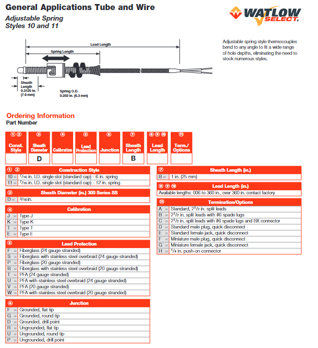
Style 10/11 (spring adjustable) bendable sheath (300 series stainless steel), spring loaded design with perforated installation, suitable for different hole depths sheath diameter of 3/16 inches, wire insulation optional fiberglass/PFA, temperature range -200 to 760 ° C (J-type) mold plates, heating plate surface temperature measurement
Style 20/21/22 (rigid sheath) straight/45 °/90 ° curved rigid sheath, compression sealed installation through the cabin wall, waterproof immersion sheath diameter of 1/8-3/16 inches, optional exposed/grounded/ungrounded junction, temperature range -200 to 1260 ° C (K-type) liquid tank, steam pipeline temperature measurement
Style 72 (clamp type) stainless steel pipe clamp+grounding junction, no drilling requirement for pipe surface fixation, compatible with 11/16-7 inch diameter wires with stainless steel braided protection, temperature range -200 to 760 ° C (J-type) chemical pipelines, HVAC systems
Style 74/75 (gasket type) brass/stainless steel thin gasket (0.016-0.01 inch thick), low profile design clamped between equipment components with a temperature measurement point thickness of only 0.4mm, does not affect component fit, temperature range -200 to 350 ° C (T-shaped) circuit board, precision component surface temperature measurement
Style 65 (PFA coating) 304 stainless steel sheath coated with 0.01 inch PFA coating threaded installation, epoxy seal resistant to acid and alkali corrosion, temperature range -200 to 300 ° C (T-shaped) electroplating tank, acid liquid temperature measurement
3. Universal common advantages
Rich insulation options: fiberglass (temperature resistant to 480 ° C), PFA (temperature resistant to 260 ° C), fiberglass+stainless steel weaving (wear-resistant), suitable for different environmental protection needs.
Flexible terminals: Supports 2.5-inch splitter, # 6 shovel shaped terminals, standard male and female plugs, 1/4-inch inserts, etc., compatible with controller/PLC connections.
Low cost adaptation: Standardized production, short delivery cycle, suitable for batch universal scenarios.
(2) Mineral Insulated (MI) Thermocouple (XACTPAK) ® Series)
1. Core positioning and applicable scenarios
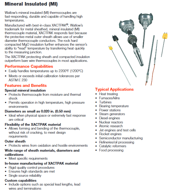
For extreme environments such as high temperature, high vibration, and high pressure, such as industrial furnaces, turbines, nuclear reactors, and semiconductor epitaxial equipment, a metal sheath+mineral insulation structure is used, which has high temperature resistance, impact resistance, and fast response characteristics.
2. Structural principles and key advantages
Structural composition: The inner core is a thermocouple wire (such as K-type nickel chromium nickel silicon), filled with compacted MgO (magnesium oxide) insulation in the middle, and the outer layer is a metal sheath (304/316 stainless steel, Alloy 600, etc.) with a minimum diameter of 0.02 inches (0.5mm).
Core advantages:
High temperature resistance: The highest temperature resistance is 1700 ° C (Type B), far exceeding the general type.
Quick response: The smaller the diameter of the sheath, the faster the response. The response time of a 0.032-inch grounding structure in still water is less than 0.02 seconds.
Resistant to harsh environments: MgO insulation is moisture-proof, heat-resistant, and corrosion-resistant, suitable for high voltage (such as steam environment) and vibration (such as engine) scenarios.
3. Typical models and applications
Model series, structural characteristics, key parameters, applicable scenarios
Style AB (stripping type) without terminals, the end of the sheath is stripped to expose the thermocouple wire, and the wiring can be customized. The diameter of the sheath is 0.02-0.25 inches, and the calibration type is J/K/T/E. The temperature range is -200 to 1260 ° C. The device is internally integrated with a customized temperature measurement module
Style AC (plug type) with standard/miniature male and female plugs, plug and play sheath diameter 0.032-0.125 inches, plug temperature resistance 200-425 ° C, temperature range -200 to 1260 ° C Laboratory equipment, portable temperature measurement
Style AR (connector type) with cast iron/aluminum/explosion-proof connector, suitable for high temperature furnace wall connector, temperature resistance of 120-200 ° C, sheath material optional Alloy 600, temperature range of 0 to 1480 ° C (R type) for high temperature industrial furnaces and heat treatment kilns
Style AT (sleeve adaptation type) long sheath design, compatible with thermocouple sleeves, corrosion-resistant sheath length 1-99 inches, spring-loaded to ensure fit with the bottom of the sleeve, temperature range -200 to 1260 ° C for chemical reaction vessels and high-pressure vessels
4. Key points for installation and maintenance
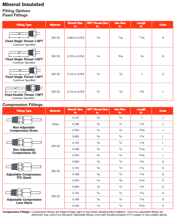
Shear bending: The minimum bending radius depends on the diameter, with a minimum radius of 0.063 inches and a shear radius of 3/16 inches to avoid excessive bending that may cause MgO insulation to fracture.
Wiring: High temperature wires (such as fiberglass insulation) should be used to avoid temperatures exceeding the tolerance value at the terminals (such as micro plugs that can withstand temperatures up to 200 ° C).
Calibration: It is recommended to calibrate once a year, and high-temperature models (such as R/S/B models) need to be calibrated using a precision high-temperature furnace.
(3) Special function thermocouple
1. EXACTSENSE ® Series (engine after treatment specific)
Core positioning: Suitable for diesel engine DPF (particulate filter), DOC (oxidation catalyst), SCR (selective catalytic reduction) systems, integrating electronic components to achieve signal conversion.
Key features:
Signal output: Supports 0-5V analog signals (RAVS/AVS), LIN 2.1/CAN J1939 digital signals, and is directly compatible with the engine ECM (control module).
Temperature measurement performance: Temperature range -40 to 1100 ° C (Haynes) ® 230 sheath), Accuracy ± 7 ° C - ± 12.5 ° C, immersion depth 25-200mm.
Environmental adaptation: Anti electromagnetic interference (100V/m 20MHz-2GHz), electronic components can withstand temperatures ranging from -40 to 120 ° C, and sheath can withstand temperatures ranging from -40 to 1100 ° C.
Typical applications: Exhaust gas temperature measurement for heavy-duty trucks, construction machinery, and marine diesel engines, optimizing regeneration efficiency and emission control.
2. MICROCOIL ™ Series (Precision Surface Temperature Measurement)
Core positioning: Precise temperature measurement for small spaces and uneven surfaces, such as chip casings, heat sinks, and micro molds.
Structural innovation:
Spiral design: 0.125-inch diameter spiral coil, spring loaded (12.5oz pressure) to ensure surface adhesion, forming an isothermal temperature measurement area to avoid local temperature difference errors.
Insulation options: Copper tip (temperature resistance of 350 ° C), Aluminum nitride tip (temperature resistance of 700 ° C), suitable for different temperature requirements.
Key parameters: Calibration type K, sheath material Alloy 718, temperature range -40 to 700 ° C, repeatability accuracy ± 1% -2%, response time<0.5 seconds.
3. TR series (RF compatible)
Core positioning: Strong electromagnetic interference scenarios such as plasma generation and radio frequency heating, such as semiconductor plasma etching machines and radio frequency heating furnaces.
Anti interference design:
High insulation: dielectric strength of 3000VDC to avoid capacitive coupling interference.
Wire design: twisted pair cable+shielding layer, improving common mode rejection ratio (CMRR) and reducing EMI induced errors.
Tip material: Silver plated copper (temperature resistant to 260 ° C), aluminum nitride (temperature resistant to 500 ° C), high thermal conductivity ensures response speed.
Key parameters: Calibration type K, thread specification 5/16-18 UNC or M8, temperature range 260-500 ° C, immersion depth 0.875-1.5 inches.
4. Multi point temperature measurement type (gradient temperature measurement)
Core positioning: Scenarios that require simultaneous monitoring of temperature gradients in multiple locations, such as petroleum distillation towers, furnaces, and large storage tanks.
Structural design:
Single sheath multiple measuring points: 2 to multiple thermocouples (mineral insulated type) are integrated into one protective tube, and the distance between measuring points can be customized (minimum 1 inch).
Material of protective tube: 316 stainless steel (corrosion-resistant), Alloy 600 (high-temperature resistant), diameter 0.125-0.25 inches.
Key parameters: Calibration type J/K, temperature range -200 to 1260 ° C, protective tube length 6-96 inches, supporting 2-10 temperature measurement points.
Detailed explanation of core technical parameters
(1) Calibration type and temperature characteristics
Calibration type Material composition Measurement range (° C) Typical error (25 ° C) Applicable environmental precautions
J-Iron Copper (JP-JN) -200 to 760 ± 2.2 ° C or ± 0.75% moisture free, non oxidizing environment. Iron is prone to oxidation, and coarse wire gauge is recommended for temperatures above 540 ° C
K nickel chromium nickel silicon (KP-KN) -200 to 1260 ± 1.5 ° C or ± 0.4% oxidation, neutral environment, sulfur-containing environment is prone to aging, it is recommended to choose N-type
E-nickel chromium copper nickel (EP-EN) -200 to 900 ± 1.7 ° C or ± 0.5% vacuum, inert, slightly reducing environment has the highest EMF output and excellent low-temperature accuracy
Copper Copper Nickel (TP-TN) -200 to 350 ± 0.8 ° C or ± 0.3%. Copper is prone to corrosion in low-temperature, cryogenic, and humid environments, and requires protection in humid environments
N Ni Cr Si Ni Si (NP-NN) -200 to 1260 ± 1.5 ° C or ± 0.4% sulfur bearing, high-temperature oxidation environment anti-aging, instead of K type for sulfur containing scenarios
R Platinum Rhodium 13 Platinum (RP-RN) 0 to 1480 ± 0.6 ° C or ± 0.25% high temperature precision measurement of precious metals, high cost, avoiding reducing environment
S Platinum Rhodium 10 Platinum (SP-SN) 0 to 1480 ± 0.6 ° C or ± 0.25% High Temperature Precision Measurement Same as R Type, More Widely Used
B Platinum Rhodium 30- Platinum Rhodium 6 (BP-BN) 870 to 1700 ± 1.0 ° C or ± 0.5% ultra-high temperature environment with low temperature output, requiring high temperature start-up
(2) Response time and influencing factors
The response time is defined as the time it takes for the sensor to reach a step temperature change of 63.2% (T63), and the core influencing factors are:
Sheath diameter: The smaller the diameter, the faster the heat conduction and the shorter the response. For example:
0.02 inch mineral insulation type: Grounding junction<0.02 seconds (in still water).
0.125-inch mineral insulation type: grounded for 0.5 seconds, ungrounded for 1.1 seconds (in still water).
0.25 inch rigid sheath: grounded for 2.2 seconds, ungrounded for 4.1 seconds (in still water).
Junction type: Grounded junction (welded to the sheath) has the fastest response, followed by exposed junction, and ungrounded junction (insulated from the sheath) has the slowest response.
Medium type: The response in liquid is faster than that in gas (liquid has high thermal conductivity), such as 0.032 inches grounded in still water for 0.02 seconds and 0.07 seconds in flowing air.
(3) Wire resistance and wiring
Wire specifications: commonly used 20-28 gauge, double wire structure, resistance value (at 20 ° C):
Line 24 gauge: J-type 0.928 Ω/double foot, K-type 1.49 Ω/double foot, T-type 0.768 Ω/double foot.
Line 20 specifications: J-type 0.367 Ω/double feet, K-type 0.589 Ω/double feet, T-type 0.304 Ω/double feet.
Wiring suggestion: For long distances (>100 feet), a thick wire gauge (such as size 20) should be selected to avoid signal attenuation caused by excessive wire resistance; Shielded twisted pair cables are used to interfere with the environment, with the shielding layer grounded at one end (controller end).
Selection and Installation Guide
(1) Selection process (four step method)
1. Determine the temperature range of the operating conditions
Maximum temperature: Choose K/N type for 1200 ° C, R/S type for 1500 ° C, and B type for 1700 ° C.
Minimum temperature: For example, T type is selected for -196 ° C (liquid nitrogen), and J/K/E type is selected for -200 ° C.
2. Analyze environmental conditions
Medium characteristics: corrosion (choose 316 stainless steel/PFA coating), sulfur-containing (choose N-type), vacuum (choose E-type), radio frequency interference (choose TR type).
Installation space: Narrow space (choose MICROCOIL) ™/ 0.02 inch MI type), pipeline (choose Style 72), surface (choose Style 74/75).
Vibration and pressure: high vibration (choose MI type), high pressure (choose Style AT+casing).
3. Determine installation and signal requirements
Installation methods: perforation (Style 10/11), threading (Style 23/24), pipe clamp (Style 72), clamping (Style 74).
Signal types: analog signal (universal/MI type), digital signal (EXACTSENSE) ®)、 Multiple measurement points (multi-point type).
4. Verify additional requirements
Protection level: IP65 (choose NEMA 4X model), explosion-proof (choose Style AR explosion-proof connector).
Wire length and terminals: Long distance (choose thick wire gauge), plug and play (choose Style AC plug type).
(2) Key installation precautions
Junction installation:
Grounding structure: Ensure good welding with sheath, suitable for corrosive and high-pressure environments, and avoid grounding loops (multi-sensor common ground).
Non grounded junction: used to avoid grounding loops and strong electromagnetic interference scenarios, ensuring the integrity of the insulation layer (such as MgO without fragmentation).
Bare knot: only used in clean, non corrosive gas environments, with the fastest response but no protection.
Wire connection:
Polarity: Thermocouple wires are divided into positive and negative (such as K-type KP being positive and KN being negative). Connecting them in reverse will cause the readings to be reversed.
Extension line: It must be matched with the calibration type (such as J-type extension line) to avoid errors caused by using ordinary wires.
Interference protection:
Electromagnetic interference: Use shielded twisted pair cables, with the shielding layer grounded at one end, and a distance of>305mm from the power line. When crossing, it should be perpendicular at 90 °.
RF interference: Choose TR type or add EMI filter to avoid sensors being close to RF sources (such as plasma generators).
High temperature installation:
Sheath insertion depth: at least 10 times the diameter of the sheath (such as 0.125 inches of sheath inserted into 1.25 inches or more), ensuring that the temperature measurement point is in the core area of the medium.
Thermal expansion: Long sheets require reserved space for thermal expansion to avoid bending and damage at high temperatures.
Typical application cases and solutions
(1) Semiconductor wafer manufacturing (precision surface temperature measurement)
Requirement: Surface temperature monitoring of wafer stage with an accuracy of ± 1 ° C, limited space (stage gap<1mm), temperature range of 50-300 ° C.
Solution: MICROCOIL ™ Micro thermocouple (Style MC), 0.125-inch spiral coil, aluminum nitride tip (temperature resistant to 700 ° C), ungrounded junction to avoid grounding loop, wire selected with FEP insulation 26 (temperature resistant to 260 ° C).
Advantages: Low profile (<0.5mm) does not affect wafer transfer, isothermal area ensures surface temperature measurement accuracy, and resists wafer carrier vibration.
(2) Diesel engine SCR system (exhaust gas temperature measurement)
Requirement: SCR inlet/outlet exhaust gas temperature monitoring, temperature 200-800 ° C, signal compatible with CAN J1939 protocol, anti vibration and exhaust gas corrosion.
Solution: EXACTSENSE ® Series (Part No. OKK30B2A), sheath material Haynes ® 230 (temperature resistance 1100 ° C), CAN digital output, immersion depth 50mm, wire with fiberglass braided protection (temperature resistance 400 ° C).
Advantages: Integrated electronic components can directly output CAN signals without the need for additional transmitters. Sheath is resistant to exhaust gas corrosion and has a response time of less than 3 seconds (T63).
(3) High temperature industrial furnace (furnace gradient temperature measurement)
Requirement: Temperature monitoring at three points inside the furnace (top/middle/bottom), with a temperature range of 800-1200 ° C, to protect the pipes from slag erosion.
Solution: Multi point temperature measurement type (Style AW), protective tube material Alloy 600 (temperature resistance of 1260 ° C), diameter of 0.25 inches, 3 K-type temperature measurement points (spacing of 6 inches), protective tube length of 36 inches, wire selection of 20 gauge fiberglass insulation.
Advantages: Single protection tube enables multi-point temperature measurement, reduces furnace wall openings, and Alloy 600 is resistant to high temperature oxidation and slag erosion.
Maintenance and Calibration
(1) Daily maintenance
Regular inspection: Check monthly whether the wiring terminals are loose, whether the sheath is deformed/corroded, and whether the exposed joints are covered with pollutants.
Cleaning: Clean the sensor surface with alcohol to avoid affecting heat conduction if there is any contamination (such as oil stains, dust); If there are scratches on the PFA coating, it needs to be evaluated whether to replace it (to prevent the invasion of corrosive media).
Wire maintenance: Check whether the shielding layer is damaged, whether the insulation layer is aging (such as fiberglass insulation becoming brittle), and replace it in a timely manner if it is damaged.
(2) Calibration cycle and method
Calibration cycle:
Universal type (medium low temperature): once a year.
High temperature type (>1000 ° C): once every 6 months.
Precision scenarios (such as semiconductors): once every 3 months.
Calibration method:
Low temperature (-200 to 300 ° C): Calibrate with a constant temperature bath and standard platinum resistance (PT100).
Medium to high temperature (300 to 1200 ° C): Calibrate with a tube furnace and standard thermocouple (such as S-type).
Ultra high temperature (>1200 ° C): calibrated with a blackbody furnace and standard optical pyrometer (B/R/S type).
Calibration standard: Follow ASTM E230 standard. If the error exceeds the limit, adjust the controller offset or replace the sensor.
- OMRON
- ABB
- General Electric
- EMERSON
- Honeywell
- HIMA
- ALSTOM
- Rolls-Royce
- MOTOROLA
- Rockwell
- Siemens
- Woodward
- YOKOGAWA
- FOXBORO
- KOLLMORGEN
- MOOG
- KB
- YAMAHA
- BENDER
- TEKTRONIX
- Westinghouse
- AMAT
- AB
- XYCOM
- Yaskawa
- B&R
- Schneider
- KONGSBERG
- NI
- WATLOW
- ProSoft
- SEW
- ADVANCED
- Reliance
- TRICONEX
- METSO
- MAN
- Advantest
- STUDER
- DANAHER MOTION
- Bently
- Galil
- EATON
- MOLEX
- DEIF
- B&W
- ZYGO
- Aerotech
- DANFOSS
- Beijer
- Moxa
- Rexroth
- Johnson
- WAGO
- TOSHIBA
- BMCM
- SMC
- HITACHI
- HIRSCHMANN
- Application field
- XP POWER
- CTI
- TRICON
- STOBER
- Thinklogical
- Horner Automation
- Meggitt
- Fanuc
- Baldor
- SHINKAWA
- Other Brands
- UniOP
- KUKA
- Iba
- Beckhoff
- ADLINK
-
 Sigmatek MDD111-1 DIAS Drive Axis Module
 -
 Sigmatek DKL042 05-024-042 Terminal Module
 -
 Sigmatek DM822 Control Module
 -
 Sigmatek CDM167 12-008-167-O Module
 -
 Sigmatek TAE151 Touch Display Unit
 -
 Sigmatek DCC041 SLIDES Module 05-700-041-D
 -
 Sigmatek AKM65M-ANC2GBB0 PM Servo Motor
 -
 Sigmatek ETT221 01-230-221 Operator Terminal
 -
 Sigmatek SLIDES DAM 124 Analog Module
 -
Sigmatek AKM31C-ANCNGBB0 Servo Motor
-
 Mannesmann Demag Sigmatek CP626 Central Unit
 -
 SIGMATEK 0332.554.03 Board 371071000154
 -
 SIGMATEK 12-250-021 Base Plate Back Panel CM5V020
 -
 SIGMATEK DM162 S-DIAS Digital Mix Module
 -
 DEMAG ERGOTECH 061 381 66 Sigmatek 9842.243.02 Circuit Board
 -
 SIGMATEK CP313-1 PLC Module
 -
Sigmatek ETV0551-2 VARAN Touch Terminal
-
 Sigmatek SDM 081 FS S-Dias Safety Module
 -
 DEMAG 05-250-023 Ergotech Motherboard with Sigmatek TMS012
 -
Sigmatek CM5V020 12-250-023-K Wiring Base
-
 Sigma Tek 5000B-37 Attitude Gyro Indicator
 -
 Sigmatek SDD120-2 DIAS Drive
 -
 Sigmatek CME221 Memory Module
 -
 Sigmatek DCP640 DIAS Central Unit
 -
 Sigmatek STO040 Safety Output Module
 -
Sigmatek CET281 Control Panel
-
 Sigmatek CIPC LX800 Demag NC5 CPU
 -
 Sigmatek DKL093 05-024-093 Terminal Module
 -
 Sigmatek AI088 20-009-088 Analog Input Module
 -
Sigmatek CAI888 Analog Input Module
-
SIGMATEK CCA021 12-025-021 Analog Output Module
-
SIGMATEK 1104.579.05 Control Module
-
SIGMATEK SDI100 Digital Input Module
-
 SIGMATEK C-IPC 256MB LX800 Compact Dias
 -
 SIGMATEK 9423.090.02 Control Module
 -
SIGMATEK C-IPC 256 Power Supply 148498
-
 SIGMATEK CAI025 Analog Input Module
 -
 SIGMATEK CTO166 Digital Output Module
 -
 SIGMATEK CP112 20-004-112 Processor Module
 -
SIGMATEK CAI887 12-009-887 Safety Module
-
 Sigma-Tek 4000B-31 Directional Gyro 1U262-002-42
 -
Sigmatek C-IPC 256MB LX800 IPC Controller
-
Sigmatek C-IPC 01-450-031 Industrial PC LX800
-
Sigmatek C-IPC 256 Industrial PC Controller
-
Sigmatek CCP-531 PLC Processor Module
-
Sigmatek CDI163 Digital Input Module
-
 Sigmatek ETV0501 VARAN Terminal 12-230-0501
 -
 Sigmatek CTMS020 C-DIAS Technology Module
 -
 Sigmatek CIV512 VARAN Switch Module
 -
 Sigmatek HU011 20-080-011 Interface Module
 -
SIGMATEK SLIDES DAM 124 Module
-
 SIGMATEK C-IPC 161 01-450-161L Industrial PC
 -
SIGMATEK C-IPC 128MB VIA 733MHz 01-450-024-K
-
 SIGMATEK 12-780-012 R8-IPC Geode LX800 Module
 -
SIGMATEK CAM124 Analog Module
-
 SIGMATEK S1 032-8AF61-R4 EZ Servo Motor
 -
 SIGMATEK CTO163 Digital Output Module
 -
 SIGMATEK CCP082 12-004-082 Processor Module
 -
 SIGMATEK CRCH081 C-DIAS Temperature Module
 -
 SIGMATEK PC322-K 01-310-322-K Industrial PC
 -
SIGMATEK SDD310-2 Servo Drive
-
 SIGMATEK AI084 Analog Input Module
 -
SIGMATEK CRCH081 12-752-081 Temperature Module
-
Sigma-Tek 5000L-4 Attitude Gyro 1U284-001-3
-
 SIGMATEK CM5V020 12-250-023-K Wiring Module
 -
Sigma-Tek 4000H-6 Directional Gyro IU262-035-7
-
 SIGMATEK Dias DCP160 05-004-160 Processor Module
 -
SIGMATEK 0147.395.02 Control Module
-
SIGMATEK A1084 Control Module
-
SIGMATEK DI200 20-006-2000 Digital Input Module
-
Sigmatek DNC115 Encoder Module
-
 Sigmatek DAM122 05-017-122 Analog Module
 -
Sigmatek 9802.289.01 Control Board TA71 Display
-
Sigmatek TO127 20-007-127 Digital Output Module
-
Sigmatek DNC031 05-011-031 Digital Module
-
Sigmatek VI022 20-003-022 Interface Module
-
Sigmatek CAI085 Analog Input Module
-
 Sigmatek CP111 S-DIAS CPU Module
 -
Sigmatek CTMS030 Krauss Maffei Module
-
 Sigmatek CAM123 Control Module
 -
 Sigmatek TAE732-P 01-240-732-P Touch Display Unit
 -
Sigmatek MDM021 Digital Mixed Module
-
Sigmatek DCP642 DIAS Central Unit
-
 Sigmatek CST022 12-014-022 C-DIAS Module
 -
 Sigmatek SRO021 20-893-021 Safety Relay Output
 -
 Krauss Maffei MC5 Control System Sigmatek
 -
 Sigmatek DC061 Module 18-24VDC 300mA
 -
 Herrmann EVT0855 Ultrasonic Welder Touch Panel
 -
Sigmatek CIV521 Control Module 1.4A 2W
-
Sigmatek DDI61 05-006-161 Digital Input Module
-
SIGMATEK ETT312-E Touch Terminal 01-230-312
-
Cessna S3326-1 Sigma Tek 5000B-67 Gyro 1U149-015-9
-
SIGMATEK PS101 Power Supply Module
-
SIGMATEK 0332.554.03 Control Module 371071000154
-
 SIGMATEK ETT312-E Touch Terminal 01-230-312
 -
SIGMATEK CDM163 Control Module
-
 SIGMATEK VSV046 16-023-046 Module
 -
SIGMATEK AM221 20-017-221 Analog Module
-
SIGMATEK CTS051 12-053-051 Control Module
-
SIGMATEK AM221 20-017-221 Analog Module
-
Sigmatek CSDI161 12-891-161 Safety Input Module
-
Sigma Tek 4000C-1 Directional Gyro Indicator
-
Sigmatek ETV0501 12-230-0501 VARAN Terminal
-
Sigmatek DDM165 SLIDES Module
-
Sigmatek N100 20-011-100 Control Module
-
Sigmatek AKM54K-ANC2R-B0 PM Servo Motor
-
Sigmatek CTO166 Digital Output Module
-
Sigmatek CP212-K 20-004-212-K CPU Module
-
Sigmatek CDI161 Digital Input Module
-
Sigmatek DCC080 05-700-080-2 Control Module
-
 SIGMATEK SCP011 S-DIAS Safety CPU
 -
SIGMATEK SCP011 S-DIAS Safety CPU
-
SIGMATEK SRO022 Relay Output Module
-
SIGMATEK MDD 121 Drive Axis Module
-
SIGMATEK DSI021 SLIDES Siemens Interface
-
SIGMATEK DIAS DCP161 Module 05-004-161
-
 Sigmatek ETT312 Built-in Touch Terminal
 -
SIGMATEK DCP 643 DIAS Controller System
-
SIGMATEK CIO021 Multi I/O Module
-
SIGMATEK CTMS020 Control Module
-
 Sigmatek CME 221 Memory Module
 -
Sigmatek 0420.615.01 Control Board
-
Sigmatek CP111 20-004-111 CPU Module
-
Sigmatek 9405.065.03 Control Board
-
Sigmatek ETEK 01-450-032-K C-IPC 256MB Industrial PC
-
Sigmatek CTO163 12-007-163 Safety Output Module
-
Sigmatek TO081 20-007-081 Digital Output Module
-
 Sigmatek SI021 20-022-021 Safety Input Module


