
Allen Bradley DeviceNet Communication Module (1203-GK5/1336-GM5)
Features 1203-GK5 module 1336-GM5 board
Physical form independent module embedded board
Installation method: 35 × 7.5mm DIN rail mounting (compatible with 199-DR1 and other models of rails) directly installed inside specific SCANPort products (such as 1336 series drives)
Connection method: 8-pin mini DIN interface+SCANPort cable (up to 10m), 14 pin internal SCANPort connector (no additional cables required)
Most SCANPort products, such as 1305/1336 PLUS/1394, are only compatible with 1336 series drives (compatibility needs to be confirmed for some low-power models)
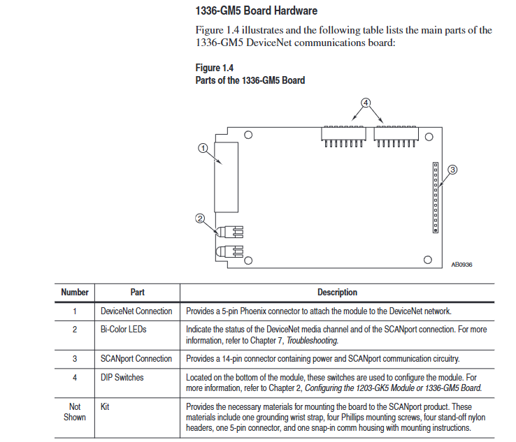
The packaging accessories include 5-pin/10 pin Phoenix connectors, DIN rail buckles with grounding wristbands, installation screws, nylon support columns, and communication housings
Allen Bradley DeviceNet Communication Module (1203-GK5/1336-GM5)
Product Overview and Core Positioning
1. Product types and differences
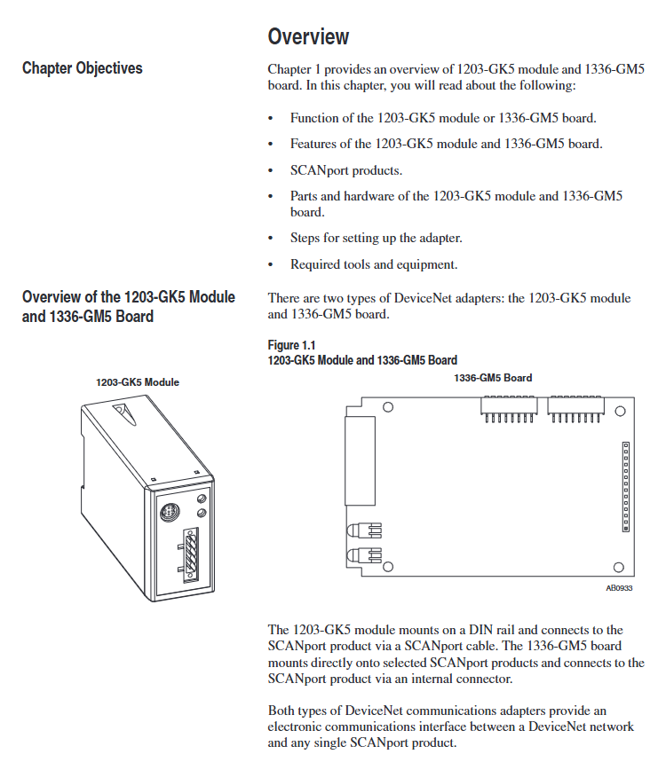
Both devices are DeviceNet communication adapters, with the same core functions but different forms and installation methods. The specific differences are shown in the table below:
Features 1203-GK5 module 1336-GM5 board
Physical form independent module embedded board
Installation method: 35 × 7.5mm DIN rail mounting (compatible with 199-DR1 and other models of rails) directly installed inside specific SCANPort products (such as 1336 series drives)
Connection method: 8-pin mini DIN interface+SCANPort cable (up to 10m), 14 pin internal SCANPort connector (no additional cables required)
Most SCANPort products, such as 1305/1336 PLUS/1394, are only compatible with 1336 series drives (compatibility needs to be confirmed for some low-power models)
The packaging accessories include 5-pin/10 pin Phoenix connectors, DIN rail buckles with grounding wristbands, installation screws, nylon support columns, and communication housings
2. Core functions and features
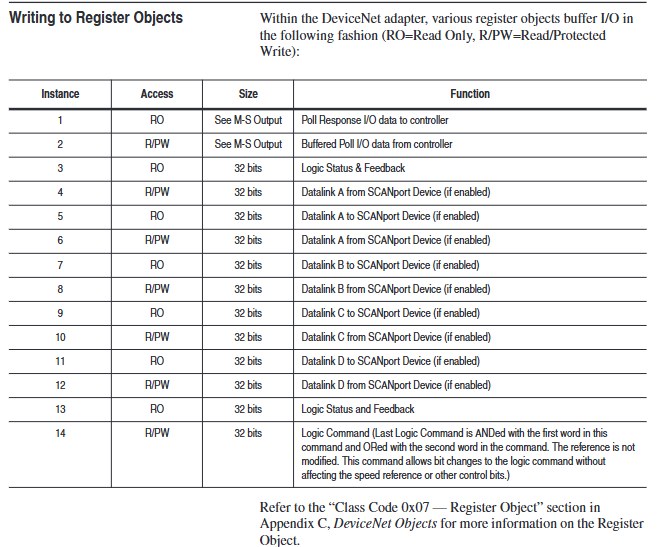
Communication conversion: Convert DeviceNet messages to SCAnport protocol, supporting polling I/O (logical instructions/reference values/feedback values) and explicit messages (parameter read/write, fault query), DeviceNet speed supports 125K/250K/500Kbps.
Flexible configuration: Set node addresses (0-63), data rates, Datalink enablement, and fault response strategies through DIP switches; Support fault node recovery (SW2-7/8 needs to be set to ON, and the offline node address needs to be modified with software).
Status monitoring: Dual color LED indicator lights (DeviceNet network status, SCANPort connection status) provide real-time feedback on communication and device health status.
Compatibility: Compatible with various SCANPort products, such as 1305 AC micro drives, 1336 series frequency converters (IMPACT/PLUS/FORCE), 1394 multi axis motion systems, etc. Most products support 1-6 peripheral connections, with an I/O word length range of 2-10 words (please refer to the product manual for details).
DIP switch configuration (core pre steps)
The DIP switches of the two devices are in the same layout (1203-GK5 is at the bottom and 1336-GM5 is at the edge of the board). They need to be adjusted after power off to take effect after power on. The specific configuration items are as follows:
1. Node address (SW2-1~SW2-6)
Function: Set the DeviceNet network node address (0-63), default is 63, and ensure that the address is unique within the network.
Configuration rule: Binary encoding, SW2-1 is the lowest bit (1), SW2-6 is the highest bit (32), for example, address 3 corresponds to "000011" (SW2-1/SW2-2 is set to ON, the rest are set to OFF).
2. Data rate (SW2-7~SW2-8)
Function: Define DeviceNet communication rate, default 125Kbps, configuration rules are as follows:
|SW2-8 (high bit) | SW2-7 (low bit) | Data rate | Description|
|0 | 0 | 125Kbps | Default value|
| 0 | 1 | 250Kbps | - |
| 1 | 0 | 500Kbps | - |
|1 | 1 | Software configuration | Requires setting through DeviceNet Manager (supports fault node recovery)|
3. Data link (SW1-1~SW1-4)
Function: Enable Datalink (2 input+2 output words per channel, up to 4 channels), default fully disabled, configuration rules:
|Switch | Function | 0 (OFF) | 1 (ON)|
|SW1-1 | Datalink A | Disabled | Enabled|
|SW1-2 | Datalink B | Disabled | Enabled|
|SW1-3 | Datalink C | Disabled | Enabled|
|SW1-4 | Datalink D | Disabled | Enabled|
Attention: It is necessary to ensure that the SCANPort product supports Datalink and that the same Datalink is not occupied by other adapters.
4. Fault response (SW1-6~SW1-8)
Function: Configure device behavior in case of network failure (communication interruption) or controller idle (programming mode), triggering SCANPort product failure by default. Configuration rules:
|Switch | Function | 0 (OFF) | 1 (ON)|
|SW1-8 | Programming/Idle Fault | Triggered Fault | Non Triggered Fault|
|SW1-7 | Communication interruption fault | Trigger fault | No trigger fault|
|SW1-6 | Standby behavior | Output zero data | Maintain last state|
Safety Reminder: Modifying fault response requires risk assessment to avoid personal injury or equipment damage caused by continuous operation of the equipment.
Installation process and electrostatic protection
1. General safety requirements
Static protection: Modules/boards contain ESD sensitive components, and grounding wristbands must be worn during operation, refer to Rockwell document 8000-4.5.2 "Anti static Damage Guide".
Power off operation: Before installing the 1336-GM5 board, all power sources of the SCANPort product must be disconnected to avoid electric shock; The installation of 1203-GK5 requires disconnecting the DeviceNet network power supply.
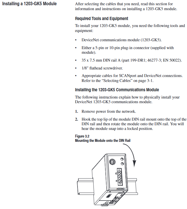
2. Installation steps for 1203-GK5 module
Rail mounting: Insert the top hook of the module into the DIN rail, rotate and fasten it, and use an ohmmeter to check the grounding (the resistance between the metal shell of the RS-232 port of the module and the rail grounding is ≤ 2 Ω).
Cable connection:
DeviceNet: 5-pin connector (point-to-point) or 10 pin connector (daisy chain), wired by color (red=PWR, white=CAN_S, blue=CAN_L, black=COM, bare wire=shielded).
SCAnport: Insert the 8-pin mini DIN interface into the cable and confirm installation with a snap sound. The cable length should be ≤ 10m and kept away from high-power cables to prevent interference.
Power on verification: The SCANPort LED is constantly green, and the DeviceNet LED is flashing green (no connection established). If there is an abnormality, refer to the troubleshooting section.
3. Installation steps for 1336-GM5 board
Preparation: Disconnect the power supply of the drive, remove the casing, and install 4 nylon support columns on the drive main control board.
Card fixing: Align the 14 pin pin of the card with the SCANPort interface and insert it, then fix it with 4 screws (to avoid damaging the card due to over tightening).
DeviceNet wiring: Connect 5-pin Phoenix connectors by color, insert them into the card interface, and tighten the screws.
Power on verification: Install the communication enclosure, restore the driver power, keep the SCANPort LED on green, and the DeviceNet LED flashing green.
DeviceNet Network Configuration (DeviceNet Manager)
1. Configuration tools and prerequisites
Software: DeviceNet Manager (Windows application) or RSNetWorx for DeviceNet, requires a 1784-PCD card or 1770-KFD adapter to connect the PC to the DeviceNet network.
Prerequisite: DIP switch configuration has been completed, module/board has been connected to the network, and RSLinx (communication interface software) has been installed on the PC.
2. Core configuration steps
(1) Online mode connection
Start DeviceNet Manager, select "Utilities>Set Up Online Connection", and choose the corresponding driver (such as 1770-KFD).
Configure communication ports (COM1/COM2), baud rate (default 38400bps), PC node address (avoid 63), network data rate (consistent with DIP switch), click "OK" to enter online mode.
(2) Create EDS file (initial configuration)
Select "Who>Network Who" to scan the network, double-click on unrecognized devices (displaying the universal icon), and a prompt "Create EDS file" will pop up. Click "Yes".
Click on 'Load from Device', enter the module/board node address, automatically load the device description, select the device icon (such as 1336. BMP) and SCANPort adapter icon (SCANPORT. BMP).
Enable "Polled Connection", set the I/O size (default 4 bytes, formula: 4+number of enabled Datalinks x 4), click "OK" to save, and rescan the network to confirm that the device icon is displayed normally.
(3) Configure PLC/SLC scanner
Taking 1771-SDN (PLC scanner) as an example:
Double click the scanner icon to enter "1771-SDN Module Configuration", click "Edit Scan List", select "Add Devices From>Who", and drag the target node into the scan list.
Select the node, click "Edit I/O Parameters", and set the polling I/O size (same as EDS configuration) and polling rate (Every Scan/Background).
Click on "Auto Map" to configure the storage address for input/output data (such as PLC N90/N100 files), and click "Map" to complete the mapping.
Select "Save To>SDN", download the configuration to the scanner, prompt "Scanner offline for 5-10 seconds", confirm and complete the configuration.
(4) Save and Verify
Save configuration file (for PLC) Used for SL7 and SLC SL4), Before exiting, confirm that the DeviceNet LED is always green (indicating connection establishment) and the SCANPort LED is always green (indicating normal communication).
Programming and Communication Implementation
1. Ladder diagram programming (RSLogix)
Implementing SCAnport product control through polling I/O requires N-file mapping (input=SCAnport → DeviceNet, output=DeviceNet → SCAnport). Example functions are as follows:
Start stop control: 1336 PLUS driver logic instruction bit definition (bit 0=stop, bit 1=start, bit 2=jog, bit 3=fault clearing), writes the operation signal to the output N-file (such as N10:1) through MOV instruction.
Reference value transmission: The frequency reference value 0-32767 corresponds to 0-maximum frequency, and N7:0 (operator set value) is written to N10:2 (driver reference value) through MOV command.
Status monitoring: Read the drive status bits (bit 1=running, bit 8=fault) from the input N-file (such as N9:1) and output them to the operator display terminal (such as O: 000).
2. Explicit message communication
Support explicit message reading and writing of parameters and fault queries through DeviceNet, following the 8:16 format (8-bit class field+16 bit instance field). The core rules are as follows:
(1) PLC scanner (1771-SDN)
Write the message to the scanner buffer (10 available buffers) using 64 block transfer write (BTW), and retrieve the response through 64 block transfer read (BTR) after completion.
Message format: including transaction ID (1-255), command (1=execute, 2=query status), port (0=channel A), size (in bytes), service code (e.g. 0x0E=get attribute), node address, class/instance/attribute.
(2) SLC scanner (1747-SDN)
Write the message to the M0 file (e.g. M0: 1.224), the scanner processes it and stores the response in the M1 file. After reading, send a "delete command" (command 4) to release the buffer.
Example: Read the number of fault queues (class 0x97, instance 0, attribute 1), store the response data in N20:53, and return the number of fault queue entries.
(3) Safety Tips
Frequent parameter writing through explicit messages can shorten the lifespan of EEPROM. It is recommended to use Datalink to handle high-frequency parameter modifications (Datalink does not write to EEPROM).
Troubleshooting and LED diagnosis
1. Interpretation of LED status
Both devices come with 2 dual color LEDs, and the corresponding fault types are as follows:
(1) DeviceNet network LED (near the DeviceNet interface)
LED Status Meaning Solution
Turn off non powered/non online. Check the power connection, confirm that the node address is unique, and verify that at least one device in the network is functioning properly
Blinking green online but no connection, no operation required (constantly on after establishing I/O or message connection)
Always on green online and connected, running normally
Flashing red I/O connection timeout reduces network traffic, check if the controller is online, and confirm that RPI (Request Packet Interval) ≤ network update time
Always on red bus offline/address conflict troubleshooting address duplication, check cable terminator (terminal resistance 120 Ω), reinstall media
(2) SCANPort status LED (away from DeviceNet interface)
LED Status Meaning Solution
Turn off the non powered/unconnected SCANPort product power supply, re plug and unplug the cable, and verify the SCANPort interface with HIM
Flashing green, no operation required to establish I/O connection (always on after connection is completed)
Constant green SCANPort communication is running normally
Flashing red configuration fault (no communication). Check if Datalink is compatible with the product, unplug the cable, and restart the device
Constant red link fault (no port recognition): Disable unsupported Datalinks, confirm that no other adapters are occupying the same Datalink, power off and restart
Constant Orange Compatibility Test Failed Contact Rockwell Technical Support
Specifications
Project 1203-GK5 Module 1336-GM5 Board
Power supply 12-25V DC, 110mA (surge 4 times/5ms) 12-25V DC, 40mA (DeviceNet power supply)
Working environment temperature 0-50 ° C, humidity 0-95%, no condensation, same as left
500m for communication distance of 125Kbps, 100m for 500Kbps, drop line ≤ 6m, same as left
Protection level NEMA 1 (IP30) depends on the host device casing
ESD protection contact discharge 4KV, air discharge 8KV, same as left
- OMRON
- ABB
- General Electric
- EMERSON
- Honeywell
- HIMA
- ALSTOM
- Rolls-Royce
- MOTOROLA
- Rockwell
- Siemens
- Woodward
- YOKOGAWA
- FOXBORO
- KOLLMORGEN
- MOOG
- KB
- YAMAHA
- BENDER
- TEKTRONIX
- Westinghouse
- AMAT
- AB
- XYCOM
- Yaskawa
- B&R
- Schneider
- KONGSBERG
- NI
- WATLOW
- ProSoft
- SEW
- ADVANCED
- Reliance
- TRICONEX
- METSO
- MAN
- Advantest
- STUDER
- DANAHER MOTION
- Bently
- Galil
- EATON
- MOLEX
- DEIF
- B&W
- ZYGO
- Aerotech
- DANFOSS
- Beijer
- Moxa
- Rexroth
- Johnson
- WAGO
- TOSHIBA
- BMCM
- SMC
- HITACHI
- HIRSCHMANN
- Application field
- XP POWER
- CTI
- TRICON
- STOBER
- Thinklogical
- Horner Automation
- Meggitt
- Fanuc
- Baldor
- SHINKAWA
- Other Brands
- UniOP
- KUKA
- Iba
- Beckhoff
-
 Basler Electric DECS-200-1L Digital Excitation Control System
 -
 Basler DECS125-15-B2C1 Excitation Control
 -
 Basler 9507900205 SSR Retrofit Voltage Regulator
 -
 Basler BE2000E Digital Voltage Regulator
 -
 Basler BE1-GPS Generator Protection System
 -
 Basler DECS-250-CN1CN1N Digital Excitation Control
 -
 Basler DGC-2020 Genset Controller
 -
 Basler BE1-81O UT3ED1LA7N0F Frequency Relay (Variant)
 -
 Basler BE1-81O UT3EE1YA9S0F Frequency Relay (Variant)
 -
 Basler BE1-81O Over/Under Frequency Relay
 -
 Basler DECS125-15 Digital Excitation Control
 -
 Basler Electric BE1-951 Overcurrent Protection System
 -
 Basler Electric BE1-700V Digital Protective Relay
 -
 Basler Electric APR63-5 Automatic Voltage Regulator
 -
 Basler Electric BE1-851 Overcurrent Protection System
 -
 Basler Electric DECS-250-LN1SN1N Excitation Control
 -
 Basler Electric BE1-87T Transformer Differential Relay
 -
 Basler Electric DECS-200-1L Excitation Control System
 -
 Basler Electric 9310300100 DECS-300 Excitation Control
 -
 Basler Electric SSE-N 125-4.5KW Shunt Exciter Regulator
 -
 Basler Electric DGC-2020HD-5NS1DNSBA Genset Controller
 -
Basler Electric BE1-81-O/UT3EE1JB7N1F Frequency Relay
-
 Basler Electric BE1-81T1EE1WA0N1F Frequency Relay
 -
 Basler Electric BE1-25M1EA6PN5R1F Sync-Check Relay
 -
 Basler Electric BE1-GPS Generator Protection System
 -
Basler Electric DECS-250-LN1SN1N Excitation Control Rev V
-
 Basler Electric DECS-250-CN2CN1N Excitation Control
 -
 Basler Electric BE1-50/51B-207 Overcurrent Relay
 -
Basler Electric DECS-300-C0N0 Excitation Control System
-
Basler Electric DECS-200 Digital Excitation Control System
-
Basler Electric DECS-250-LN1CN1N Excitation Unit
-
Basler Electric DECS-250 LN2SA1D Excitation Unit Specs
-
Basler Electric BE1-87T Transformer Relay Review
-
Basler Electric BE1-11 Protection System
-
Basler Electric BE1-GPS100-E4N1H1N Protection System
-
 Allen-Bradley 442G-MABH-R Safety Module
 -
 Beckhoff CX1030-0111 PLC Assembly Profile
 -
 FANUC IC693CPU364 PLC Module
 -
 Orange Denmark Type 200816 220 PLC Specs
 -
 OMRON C200H-SNT31 Sysmac PLC Module
 -
 Allen Bradley 20AB022A3AYNANC0 PowerFlex 70
 -
 OMRON C200HW-PCU01 Position Control Unit
 -
 ABB AO845A-eA Analog Output Module
 -
 OMRON CJ1M-CPU22 CPU Unit
 -
 Allen Bradley 100-E265ED11 Contactor
 -
 Honeywell 51304511-100 Interface Module
 -
 SOLEXY BXF3S0101N0018 Gateway Module
 -
 OMRON CJ2H-CPU65 CPU Unit
 -
 Automation Direct GS2-45P0 AC Drive
 -
 M68-2000 2-Axis Motion CNC Controller
 -
 OMRON CJ1M-CPU11 V3.0 PLC CPU Unit
 -
 OMRON CJ1W-NC413 4-Axis Positioning Controller
 -
 OMRON 3G2A3-PRO16 Programming Console HMI
 -
 Siemens 3VT8440-2AA04-2GA2 Molded Case Circuit Breaker
 -
 Siemens 3RT5045 Contactor Series
 -
 OMRON C200HS-CPU01-E SYSMAC PLC Controller
 -
 OMRON C500-NC103-E Positioning Control Unit
 -
 OMRON CJ1W-TC001 Temperature Control Unit
 -
 OMRON NJ301-1100 NJ-PA3001 PLC System EtherCAT
 -
 Pilz 773100 M1P Safety Relay Base Unit
 -
 Siemens SINUMERIK 840D SL NCU 720.3B with PLC 317-3 PN/DP
 -
 Siemens 6AV6618-7GD01-3AB0 HMI Panel
 -
 OMRON F150-C15E-3 Vision Mate Controller PLC Overview
 -
 Mitsubishi MELSEC A Series PLC System A63P A3ACPU A616AD A68RD3
 -
 M68-2000 2 Axis Motion Controller SCE SERVO CNC
 -
 OMRON FZ-S2M PLC Camera Vision System
 -
 VISOLUX SLVA-4K PLC Module from Elektronik GmbH
 -
 OMRON CJ1M-CPU23 V2.0 PLC CPU Unit
 -
 ABB AI86-16CHF PCB Card 5761751-9 B Specifications
 -
 Allen-Bradley 100-D140ZJ22L Contactor Overview
 -
 Merlin Gerin PB80 PLC Rack
 -
 WEIR WE203 Power Supply PLC
 -
 OMRON NX-TS3102 Temperature Input Unit
 -
 Siemens 6ES7146-6FF00-0AB0 I/O Module
 -
 Fanuc A16B-3300-0057 Circuit Board
 -
 OMRON CJ1W-IDP01 Input Module
 -
 Siemens 6FX2007-1AD13 Handheld Unit
 -
 Gems EM54 PLC Module PCB
 -
 Beckhoff CX2030-0121 Embedded PC CPU
 -
 OMRON NJ301-1100 Machine Automation Controller
 -
 Biesse Rover CNI PLC 2153 030 7146.30 Numerical Control Module
 -
 OMRON CJ1W DA08V Analog Output Module
 -
 OMRON CS1D ETN21D Ethernet Module
 -
 Allen Bradley 1768 L43 CompactLogix Controller
 -
 Schneider TWDLMDA40DTK Twido PLC Module
 -
 Mitsubishi NZ2EX2B 60AD4 Analog Input Module
 -
 OMRON NS8 TV00B V2 Touch Display Panel
 -
 Mitsubishi AY71 CMOS TTL Output Module
 -
 OMRON C500 CPU11 E Processor Module
 -
 OMRON CJ1W PTS51 Temperature Input Module
 -
 Siemens 6SL3100-1DE22-0AA1 600V DC Supply
 -
 OMRON CJ1M-CPU23 PLC CPU 9‑Pin Serial
 -
 Schlumberger IMT4N 24‑250VAC 48‑230VAC PLC Timer
 -
 OMRON CJ1M-CPU22 PLC CPU Unit V2.0
 -
 Allen‑Bradley 2711P-B7C6D2 Touch Screen PanelView
 -
 ADSP-2181KST-160 Analog Devices DSP IC Specs
 -
 Schneider LC1F400 400A Contactor Specifications
 -
 Yaskawa SGDH-10DE-OY 1kW 400V Servo Drive
 -
 Schneider TM262L10MESE8T M262 PLC 5ns Inst
 -
 Mitsubishi AA104VJ05 10.4in LCD Panel Specs
 -
 Allen Bradley 1761-L32BWA MicroLogix 1000 PLC
 -
 Siemens 6ES7431-7KF00-0AB0 Analog Input Module
 -
 Allen Bradley 1769-OB16 Output Module
 -
 Siemens 6ES7131-1BL12-0XB0 Input Module
 -
 Beckhoff EP7041-3002 EtherCAT Box Module
 -
 Siemens RK7243-2AA30-0XB0 Communication Module
 -
 Siemens 4AM5742-8DD40-0FA0 Transformer
 -
 Siemens 3TK2834-1BB40 Safety Relay
 -
 Brother BAS 311 Sewing Machine Circuit Board
 -
Yaskawa SGDH-10DE-OY Servo Driver
-
 OMRON C60H C6DR DE V1 Sysmac PLC
 -
 MITSUBISHI ELECTRIC A2ACPU21 S1 CPU Module
 -
 ABB BAILEY INNPM12 Network Process Module
 -
 HONEYWELL 620 0073C IPC PLC Module
 -
 Mitsubishi 15050 PR02B PLC Circuit Board
 -
 SIEMENS 6SY7000 0AC37 Drive Control Module
 -
 OMRON TJ2 ECT16 Traxial EtherCAT Controller
 -
 GE Fanuc IC698PSD300D Power Supply Module
 -
 Texas Instruments Series 505 16 Position Base
 -
 OMRON YASKAWA SGDH 10DE OY Servo Drive
 -
 Allen‑Bradley 440G-MT Safety Interlock Switch Specs
 -
 Rubycon PD27A 24V 8A Power Supply Module
 -
 SK-H1-GDB1-F11D PLC Gate Driver Board Kit
 -
 VIPA 441-4UA14 451-4UA14 PLC Module Rack
 -
 Mitsubishi FX5U-80MT ESS PLC Controller Specs
 -
 Mitsubishi Q64TCRTN Temperature PLC Module
 -
 GE 1C31170G Rev10 PLC Circuit Board Module
 -
 Schneider TWDLMDA40DTK PLC Controller Module


