Allen Bradley 1203-CN1 ControlNet Communication Module
Allen Bradley 1203-CN1 ControlNet Communication Module
Product Overview and Core Positioning
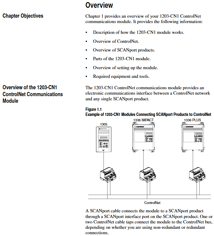
Product Function: As a bridge between the ControlNet network and SCAnport products, the module can convert ControlNet messages into signals recognizable by SCAnport products, supporting the transmission of scheduled I/O data (such as logical instructions, analog reference values) and non scheduled messages (such as parameter read/write, fault query). The ControlNet network speed reaches 5Mbps, ensuring real-time and deterministic performance.
Adaptation scenarios: Compatible with various Allen Bradley SCANPort products, including 1305 AC micro drives, 1336 series inverters (IMPACT/PLUS/FORCE), 1394 multi axis motion control systems, SMC Dialog Plus controllers, etc. Different products support 1-6 peripheral connections, with an I/O word length range of 0-10 words (depending on the product model).
Hardware composition: The core hardware interfaces and components of the module are shown in the table below:
|Component Name | Function Description|
|DIN rail mounting seat | Fixed module and electrically grounded, compatible with 35 × 7.5mm DIN rails (models 199-DR1, etc.)|
|ControlNet coaxial interface (A/B channels) | Connect ControlNet cable taps, supporting redundant/non redundant network configurations|
|Two color LED indicator lights | 4 status lights (ControlNet A/B channels SCANport、 The module itself is used for fault diagnosis|
|SCANPort interface | 8-pin circular mini DIN connector, connected to SCANPort products through a dedicated SCANPort cable|
|ControlNet Node Address Indicator | Press the key to set the node address (0-99), which needs to be powered off and restarted to take effect, ensuring that the address is unique within the network|
|24V DC power interface | Supports multi module Daisy chain power supply, reduces wiring complexity|
|Network Access Port (RJ-45) | To connect ControlNet network devices, a 1786-CP cable and a 1784-KTCX communication card are required|
|RS-232 serial port | Used for parameter configuration and firmware upgrade, requires 1203-SFC serial port cable and terminal simulation software/VT100 terminal|

Installation and electrostatic protection
1. Installation preparation
Tools and equipment: Grounding wristband (included with module), 1/8 inch flathead screwdriver, blunt tool (set node address), ohmmeter, SCANPort cable (such as 1202-C03/C10, up to 10m), ControlNet tap (such as 1786-TPS/TPR, redundant configuration requires 2).
Static protection: The module contains ESD sensitive components, and a grounding wristband must be worn during operation. Refer to Allen Bradley document 8000-4.5.2 "Guidelines for Preventing Static Damage".
2. Installation steps
Set node address: Use a blunt tool to press the "+/-" keys to set a unique address (0-99). It needs to be powered off and restarted to take effect. Avoid using pencils/pens to prevent damage to the switch.
Rail installation: Insert the top hook of the module into the DIN rail, rotate and fasten it, and use an ohmmeter to check the rail grounding (the resistance between the metal shell of the RS-232 port of the module and the rail grounding is ≤ 2 Ω).
Cable connection: Insert the SCANPort cable alignment interface (hear a snap sound); Screw the ControlNet tap into the corresponding A/B channel; 24V DC power supply connection (supports multi module cascade power supply).
Installation verification: After power on, the SCANPort and ControlNet LEDs remain constantly green, and the module LED flashes green (when network configuration is not completed). If the LED status is abnormal, the wiring needs to be checked.
3. Module removal
After power failure, disconnect all cables (SCANPort cables need to be pressed and pulled out), pry the release buckle with a screwdriver, remove the module, and maintain grounding protection throughout the process.
Basic configuration and operation
1. Serial port connection and parameter configuration
(1) Connection preparation
Hardware: 1203-SFC serial port cable (connecting module RS-232 port to PC/terminal).
Software: PC needs to install terminal simulation software (such as Windows HyperTerminal) or use VT100 compatible terminals.
(2) Serial port configuration steps
Software settings: default baud rate of 9600 (parameter 21 can be modified, supports 2400/4800/19.2K/38.4K), data bit 8, no checksum, stop bit 1, no flow control; Simulate to select VT100 mode.
Access main menu: Press Enter to enter the module main menu, supporting 7 functions:
1: Display/edit parameters; 2: Specify parameter number for query; 3: Display event queue; 4: Display current I/O data; 5: Display DF1 protocol statistics; 6: View serial number; 7: Firmware upgrade.
(3) Key parameter configuration
The default parameters of the module support 16 bit logic instructions/status and 16 bit reference/feedback values. When the SCANPort product triggers a fault in PLC programming mode or network failure, the following parameters can be used to adjust the function:
Parameter Number Name Function Description Default Value
4 CMD/Stat enable/disable logical instructions from ControlNet to SCAnport/simulate reference data transfer 1 (enable)
- ABB
- General Electric
- EMERSON
- Honeywell
- HIMA
- ALSTOM
- Rolls-Royce
- MOTOROLA
- Rockwell
- Siemens
- Woodward
- YOKOGAWA
- FOXBORO
- KOLLMORGEN
- MOOG
- KB
- YAMAHA
- BENDER
- TEKTRONIX
- Westinghouse
- AMAT
- AB
- XYCOM
- Yaskawa
- B&R
- Schneider
- Kongsberg
- NI
- WATLOW
- ProSoft
- SEW
- ADVANCED
- Reliance
- TRICONEX
- METSO
- MAN
- Advantest
- STUDER
- KONGSBERG
- DANAHER MOTION
- Bently
- Galil
- EATON
- MOLEX
- DEIF
- B&W
- ZYGO
- Aerotech
- DANFOSS
- Beijer
- Moxa
- Rexroth
- Johnson
- WAGO
- TOSHIBA
- BMCM
- SMC
- HITACHI
- HIRSCHMANN
- Application field
- XP POWER
- CTI
- TRICON
- STOBER
- Thinklogical
- Horner Automation
- Meggitt
- Fanuc
- Baldor
- SHINKAWA
- Other Brands


