
How to install the Rockwell Automation 1756 series ControlNet communication module?
Model Core Features Applicable Scenarios
1756-CN2 standard media (non redundant), conventional industrial environment without anti-corrosion coating, single network link
1756-CN2K standard media (non redundant), with anti-corrosion coating (model ending with "K" mark), corrosive industrial environment (such as chemical and metallurgical)
1756-CN2R redundant media (dual link A/B), high reliability demand scenario without anti-corrosion coating (such as energy, transportation)
1756-CN2RK redundant media (dual link A/B) with anti-corrosion coating and high reliability requirements scenario
1756-CN2RXT redundant media, wide temperature design (-25~70 ℃), without anti-corrosion coating for extreme temperature environments (such as outdoor and refrigerated)
How to install the Rockwell Automation 1756 series ControlNet communication module?
Product Family and Core Positioning
1. Model classification and functional differences
The 1756 series ControlNet module is divided into "media type", "corrosion resistance", and "temperature adaptation range" to meet the needs of different industrial scenarios. The specific model functions are as follows:
Model Core Features Applicable Scenarios
1756-CN2 standard media (non redundant), conventional industrial environment without anti-corrosion coating, single network link
1756-CN2K standard media (non redundant), with anti-corrosion coating (model ending with "K" mark), corrosive industrial environment (such as chemical and metallurgical)
1756-CN2R redundant media (dual link A/B), high reliability demand scenario without anti-corrosion coating (such as energy, transportation)
1756-CN2RK redundant media (dual link A/B) with anti-corrosion coating and high reliability requirements scenario
1756-CN2RXT redundant media, wide temperature design (-25~70 ℃), without anti-corrosion coating for extreme temperature environments (such as outdoor and refrigerated)
2. Core advantages of ControlNet network
The ControlNet network connected to the module combines I/O network and Peer to Peer network functions, with the core features of:
Deterministic communication: ensuring repeatable and low latency transmission of critical control data;
Support redundancy: Redundant models (CN2R/CN2RK/CN2RXT) achieve network fault redundancy switching through dual links (A/B) to improve system stability.
Environmental requirements and safety certification
1. Basic environmental standards
Pollution level: only applicable to industrial environments with pollution level 2 (defined by IEC/EN 60664-1, which means the air contains only a small amount of non-conductive dust);
Overvoltage category: Class II application (IEC/EN 60664-1), suitable for downstream equipment in industrial distribution systems;
Altitude: up to 2000 meters (6562 feet), no need to downgrade for use;
Installation form: Open device, to be installed in an enclosure that meets the following requirements:
Protection level: at least IP54 (EN/IEC 60529);
Flame retardant rating: Non metallic shells must meet a 5VA flame spread rating;
Operation restriction: Tools are required to open the inside of the casing to prevent personnel from coming into contact with live parts.
2. Hazardous Area Certification
The module has been certified for hazardous areas in multiple regions, and the requirements for different regions are as follows:
Core requirements for certification areas
North America (Class I, Div 2) is suitable for A/B/C/D hazardous areas (such as environments containing flammable gases), with a temperature code of T4;
It is strictly prohibited to plug in or unplug modules/wiring in non power off or unknown non hazardous areas;
Components cannot be replaced, otherwise they may compromise their suitability for hazardous locations.
ATEX/UKEX equipment group II, category 3, protection type "Ex ec IIC T4 Gc" (increased safety type);
Only applicable to Zone 2 hazardous areas (where explosive gas environments rarely occur or occur in the short term);
It needs to be used with a UKEX/ATEX certified casing (IP54 or above).
IECEx certification protection type is the same as ATEX (Ex ec IIC T4 Gc), suitable for Zone 2 hazardous areas;
Transient protection must be met (peak voltage at the power supply end ≤ 140% of the rated value).
3. Requirements for electrostatic protection
The module is sensitive to static electricity, and the following should be followed during operation:
Contact with grounded objects to release static electricity, or wear a grounded wristband;
Do not touch module connectors, pins, and internal circuits;
When not in use, it should be stored in anti-static packaging;
Prioritize using anti-static workbenches.
Installation and wiring operations
1. Preparation before module installation
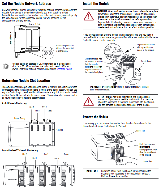
Slot position: Supports any size of ControlLogix chassis and can be installed in any slot (ensuring sufficient power capacity);
Redundant system requirements: The primary/backup modules need to be installed in the same slot of the corresponding chassis (such as the primary module in slot 3, and the backup module also needs to be in slot 3 of the backup chassis).
Network address setting:
Address range: Independent chassis modules range from 01 to 99, redundant chassis modules range from 01 to 98 (00 is an invalid address, only used for resetting);
Setting method: Adjust through the two digit dip switch on the side of the module (ten digits on the left and one digit on the right), ensuring that the address is unique within the same network.
2. Module installation and disassembly steps
(1) Installation steps
Confirm that the power supply of the chassis has been disconnected (power must be cut off in hazardous areas, and normal environments can support live plugging, but it is not recommended);
Align the module circuit board with the upper and lower rails of the chassis, and smoothly push it into the backplane connector;
Confirm that the module is flush with the power/other modules and not loose (do not forcefully press to avoid damaging the connector).
(2) Disassembly steps
Press the upper/lower tabs on both sides of the module to unlock it;
Smoothly slide the module out of the chassis, and power off in hazardous areas first.
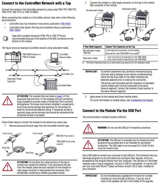
3. ControlNet network wiring (Tap connection)
The module needs to be connected to the network through a ControlNet tap (Tap, such as 1786-TPR/TPS/TPYR/TPYS/TCT2BD1), with the following specific requirements:
Media type wiring method
Non redundant (CN2/CN2K) only connects the tap to module A channel (B channel is not used), and the tap needs to be selected as a direct connection type (such as 1786-TPS) to adapt to the BNC interface at the bottom of the module
Redundant (CN2R/CN2RK/CN2RXT) tap A is connected to module A channel, and tap B is connected to module B channel; Dual links need to be simultaneously connected to the network backbone (Trunk Line A/B)
Key wiring precautions:
Unused ports (such as the B channel of CN2) need to retain protective plugs (pre installed with the "K" model) to ensure the anti-corrosion level;
When the tap changer is disconnected from the module, it is necessary to immediately cover it with a dust cap to prevent the metal part from contacting the grounding surface;
In a redundant system, the main/backup modules need to be connected to the same network segment (such as the main module A channel connected to Trunk A, and the backup module A channel also needs to be connected to Trunk A).
4. USB port usage specifications
The module is equipped with a USB 2.0 Type B port, which is only used for temporary local programming. Core limitations:
Prohibited from use in hazardous areas;
Cable length ≤ 3 meters (9.84 feet), cannot be connected to a USB hub;
RSLinx Classic 2.55 and above software must be installed;
It is prohibited to upgrade multiple module firmware through USB at the same time to avoid upgrade failure.
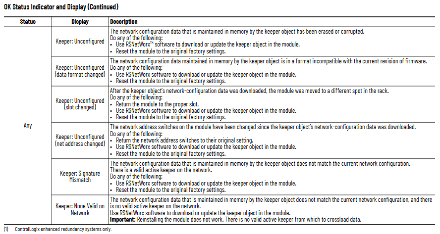
Module reset and troubleshooting
1. Restore factory settings (reset operation)
When a module needs to clear configuration or fix exceptions, the following steps can be performed:
Disconnect the power supply of the chassis and remove the module;
Set the dip switch to "00" (invalid address, only used for reset);
Reinstall the module and connect the power supply;
After the module displays "Reset Complete Change Switch Settings", disconnect the power and remove the module;
Return the dip switch to the target address (01~99/98), reinstall and power on.
2. Core methods for troubleshooting
By using the OK status indicator light and network channel indicator light (A/B) of the module to locate the fault, the key status interpretation is as follows:
(1) OK status indicator light (core fault diagnosis)
Reason and solution for malfunction of indicator light status display information
Turn off power failure or internal failure: Check the power connection and module for tightness. If it is ineffective, replace the module
Reset Complete Change Switch Settings address to 00 (invalid): Reset valid address (01~99/98)
Frequent red FAIL power on test failure: replace module directly
Flashing red DUPLICATE NOTE DETECTED Network address conflict: Replace with unique address
Flashing red Image update Needed firmware needs to be updated: Use ControlFLASH software to upgrade Boot image
Evergreen/Blinking Green CPU=xx% (xx ≥ 80) CPU utilization is too high (over 80%): Check the number of network connections and optimize the control program
Blinking green NET ERR network wiring error or no other nodes: Check cables, terminators, and ensure that at least one other node is online
(2) Network channel indicator light (A/B channel status)
Interpretation of indicator light status channel (A/B) status
Evergreen is operating normally, and channel communication is functioning properly
Flashing green/extinguishing temporary error, module can self recover
Flashing red/off media malfunction (such as disconnection, looseness) or no other nodes: Check cables, terminators, and add online nodes
Constant red channel fault: power off reset module, if ineffective, contact Rockwell technical support
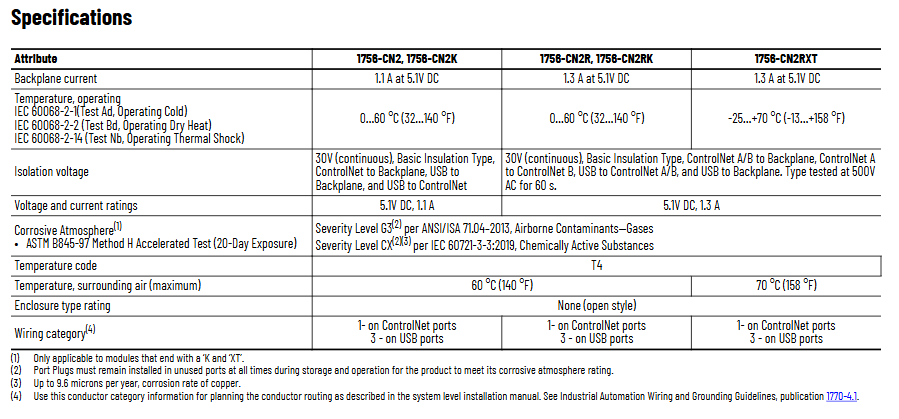
Key technical parameters
Parameter category 1756-CN2/CN2K 1756-CN2R/CN2RK 1756-CN2RXT
Backboard current 1.1A (5.1V DC) 1.3A (5.1V DC) 1.3A (5.1V DC)
Working temperature: 0~60 ℃ (32~140 ℉) 0~60 ℃ (32~140 ℉) -25~70 ℃ (-13~158 ℉)
Isolation voltage 30V DC (continuous), basic insulation between ControlNet/USB and backplane (500V AC withstand voltage for 60 seconds) on the same left (redundant models additionally support A/B channel isolation) on the same left
Anti corrosion grade (with "K") ASTM B845-97 G3 grade (ANSI/ISA 71.04), IEC 60721-3-3 CX grade same as left
The wiring category for ControlNet ports is Class 1, and for USB ports it is Class 3. Same as left
- OMRON
- ABB
- General Electric
- EMERSON
- Honeywell
- HIMA
- ALSTOM
- Rolls-Royce
- MOTOROLA
- Rockwell
- Siemens
- Woodward
- YOKOGAWA
- FOXBORO
- KOLLMORGEN
- MOOG
- KB
- YAMAHA
- BENDER
- TEKTRONIX
- Westinghouse
- AMAT
- AB
- XYCOM
- Yaskawa
- B&R
- Schneider
- KONGSBERG
- NI
- WATLOW
- ProSoft
- SEW
- ADVANCED
- Reliance
- TRICONEX
- METSO
- MAN
- Advantest
- STUDER
- DANAHER MOTION
- Bently
- Galil
- EATON
- MOLEX
- DEIF
- B&W
- ZYGO
- Aerotech
- DANFOSS
- Beijer
- Moxa
- Rexroth
- Johnson
- WAGO
- TOSHIBA
- BMCM
- SMC
- HITACHI
- HIRSCHMANN
- Application field
- XP POWER
- CTI
- TRICON
- STOBER
- Thinklogical
- Horner Automation
- Meggitt
- Fanuc
- Baldor
- SHINKAWA
- Other Brands
- UniOP
- KUKA
- Iba
- Beckhoff
-
 OMRON C60H C6DR DE V1 Sysmac PLC
 -
 MITSUBISHI ELECTRIC A2ACPU21 S1 CPU Module
 -
 ABB BAILEY INNPM12 Network Process Module
 -
 HONEYWELL 620 0073C IPC PLC Module
 -
 Mitsubishi 15050 PR02B PLC Circuit Board
 -
 SIEMENS 6SY7000 0AC37 Drive Control Module
 -
 OMRON TJ2 ECT16 Traxial EtherCAT Controller
 -
 GE Fanuc IC698PSD300D Power Supply Module
 -
 Texas Instruments Series 505 16 Position Base
 -
 OMRON YASKAWA SGDH 10DE OY Servo Drive
 -
 Allen‑Bradley 440G-MT Safety Interlock Switch Specs
 -
 Rubycon PD27A 24V 8A Power Supply Module
 -
 SK-H1-GDB1-F11D PLC Gate Driver Board Kit
 -
 VIPA 441-4UA14 451-4UA14 PLC Module Rack
 -
 Mitsubishi FX5U-80MT ESS PLC Controller Specs
 -
 Mitsubishi Q64TCRTN Temperature PLC Module
 -
 GE 1C31170G Rev10 PLC Circuit Board Module
 -
 Schneider TWDLMDA40DTK PLC Controller Module
 -
 Omron FQM1-MMA22 Motion Control Module Specs
 -
 OMRON CJ1W-NCF71 Position Control Unit Specs
 -
 Schneider TSXETY4103 Ethernet Module
 -
 Mitsubishi Q12PHCPU Process CPU
 -
 Yaskawa 3G3HV-A4022-CE AC Drive
 -
 Cincinnati Milacron 3-533-0669G Temperature Control Board
 -
 Allen Bradley 20AC030A3AYNANC0 PowerFlex 70 Drive
 -
 Siemens 6ES7314-6BG03-0AB0 CPU 314C-2 DP
 -
 Carrier 17EX54007903 PLC Module
 -
 OMRON CS1W-V600C12 ID Controller Module
 -
 Honeywell 51402755-100 PCB Card
 -
 Heidenhain ECN 113 Rotary Encoder
 -
 OMRON B7AM-8B16 I/O Terminal Block
 -
 Fanuc A06B-6110-H026 Power Supply Module
 -
 Schneider TSXETG3021 Ethernet Gateway
 -
 OMRON CS1W-CLK21-V1 Controller Link Unit
 -
 NP1W6406T-Z704 PLC I/O Module
 -
 OMRON CJ1W-DA08C Analog Output Module
 -
 Yaskawa 3G3HV-A4022-CE AC Drive
 -
 OMRON NB7W-TW01B CP1L-EL20DR-D Power Panel
 -
 OMRON C500-NC103-E Position Control Unit
 -
 Steag Hamatech PLC DCS Servo Control System
 -
 Siemens 6SN1123-1AA00-0DA1 Power Supply Module
 -
 GE IC693CHS391H CPU & AD693CMM301A PLC Module
 -
 Siemens 6FC5303-0AF23-1AA1 PLC Control Panel
 -
 Square D CM4000T PowerLogic Circuit Monitor J1 F16
 -
 Siemens 6FX5002-5DG10-1BA0 MOTION-CONNECT 500 Cable
 -
 Schmersal SRB324ST 101195504 Safety Relay 24V
 -
 Mitsubishi 15050-PR02A PLC Circuit Board Module
 -
 OMRON CQM1-AD041 Analog Input PLC Module
 -
 Beckhoff EL5042 EtherCAT PLC Terminal Module
 -
 OMRON C200HW-MC402-E Motion Control Unit
 -
 C36TC0UA1100 Industrial Temperature Controller
 -
 NL8048BC24 12 Industrial Control LCD Module
 -
 OMRON R88D Servo Drive and Motor System
 -
 OMRON CS1W CLK21 V1 Controller Link Module
 -
 OMRON YASKAWA R7M A20030 S1 D Servo Motor
 -
 SIEMENS 6AV2128 3KB06 0AX1 Unified Comfort Panel
 -
 Schneider Electric METSEPM8240 PowerLogic Meter
 -
 Advanced AMCI 1PLC 1 31F Programmable Limit Switch
 -
 ABB PM582 ETH Programmable Logic Processor
 -
 SIEMENS 6FC5110 0CB01 0AA0 CPU Control Board
 -
 Schleicher P03GS13A CPU Module
 -
 Siemens 6SN1123-1AA00-0BA1 Power Module
 -
 Mitsubishi A1S61PN Power Supply Module
 -
 Yaskawa CPS-IONB DC Power Supply Module
 -
 Siemens 6ES7215-2BD00 CPU 215-2
 -
 Mitsubishi A2ACPU MELSEC PLC System Kit
 -
 ProSoft 3150-MCM Communication Module
 -
 Mitsubishi OSE104ET Incremental Encoder
 -
 OMRON CJ1W-AD081-V1 Analog Input Module
 -
 Broadcom BCM5464A1KRB Quad Port Ethernet IC
 -
 Modicon M221-24IO TM221C24 PLC 24 PNP Transistor
 -
 Allen-Bradley 1321-3R160-B Line Reactor 3R160B
 -
 Beckhoff CX1020-0012 Embedded PLC Module Specs
 -
 Turck BL20-PF-24VDC-D Power Feed Module Specs
 -
 Siemens 6SY7000-0AC37 Power Supply Module
 -
 Yaskawa SGDH-10DE-OY 1kW 400V Servo Drive Specs
 -
 Omron 3G3SV-BB015-E 1.5kW 220V VFD Specs
 -
 Uni-Pro CPU91-PLC J 23.020167X Processor Module
 -
 PASABAN MTC-3044 PLC Rack Power Supply 4835-A
 -
 XYCOM 3015T Operator Interface Panel BIN4.4.4
 -
 OMRON CJ1W-MD261 Mixed I/O Module
 -
 Omron NJ301-1100 PLC CPU eCat EIP Specs
 -
 Omron F500-C15-ETN Vision System PLC Module
 -
 Modicon M241-24IO TM/T2UK PLC with Ethernet
 -
 SIXNET YS-800-001 RTU PLC Module
 -
 BEMAC UST-202-D Interface Board 1307D V08B2
 -
 Yaskawa JANCD-MMOIC-02 Drive Circuit Board
 -
 ABB 3BSE005028R1 SDCS-COM-1 Comm Board
 -
 Omron 3G3MX2-A4110 A4150 Inverter Drives Specs
 -
 KEYENCE CA-E100 PLC Module
 -
 GE IC693ALG223-GB Analog Input Module Specs
 -
 ABB BAILEY IMMFP01 Multi Function Processor System
 -
 SIEMENS 6FC5372 0AA00 0AA1 NCU 7202 Controller
 -
Modicon TM241CE4 40I O Transistor Programmable Controller
-
 SIEMENS 6ES7 315 2EH13 0AB0 CPU 3152 PN DP
 -
 NORIS A1 91 PCB Card Rack Module System
 -
 SIEMENS 6ES7 313 5BE01 0AB0 Compact CPU
 -
 SCHNEIDER ELECTRIC S144B MICROLOGIC 60A Trip Unit
 -
 CNI PLC269 v3 Control Module Board Rev H
 -
ABB BAILEY IIMCP02 Processor Module
-
 OMRON NT20S ST121 EV3 Operator Interface Terminal
 -
 OMRON NS-CA001 Video Input Unit
 -
 GE Fanuc IC695CHS012 RX3i Backplane
 -
 Allen Bradley 2711E-K14C6 PanelView 1400e Terminal
 -
 Siemens Sinamics CCB 10000432.71 Power Cell
 -
 Siemens 6SL3210-1SE21-8UA0 Power Module PM340
 -
 Yaskawa CIMR-F7A20P4 AC Drive
 -
 Beckhoff EP1918-0002 EtherCAT Box I/O Module
 -
 OMRON CQM1-TC001 Temperature Control Module
 -
 GE Fanuc SGHA36AT0400 Industrial Contactor
 -
 OMRON NJ501-1500 PLC Machine Automation Controller
 -
 Mitsubishi MAZAK QX084 Power Supply MELDAS 500 CNC
 -
 B&R 0AC808.9 PLC Automation Module
 -
 OMRON CP1H-XA40DT1-D PLC Module
 -
 G&W Electric PLC15 5111 011 15kV Capnut Assembly
 -
 GE DS200SLCCG3AGH PCB Circuit Board
 -
 Siemens SINUMERIK 6FC3981-4FD PLC Extension
 -
 OMRON F300-DC I/O Image Processing Unit
 -
 FANUC A06B-0314-B002 AC Servo Motor
 -
 GC-S84 Programmable Controller Logic Module
 -
 PASABAN MONTELEC MTC3001-DC Drive Control PLC
 -
 Allen Bradley 100E460EJ11 Auxiliary Contactor
 -
 Bosch Rexroth 1070075337-101 Card Parameters
 -
 HMS Anybus AB7646-F Gateway Specifications
 -
 Bosch 062633-303401 CNC Servo PLC Card
 -
 TI 500-5023 Series PLC Power Supply
 -
 Siemens C98043-A7002-L1-12 Circuit Board
 -
 Omron E5CC-RX3A5M-000 Controller


